Transcription
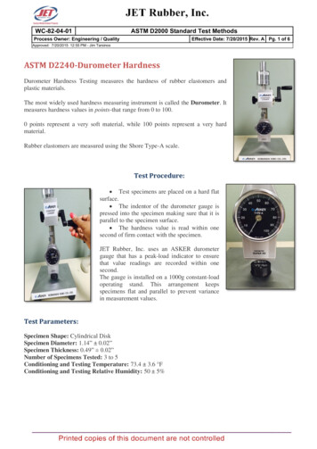
This international standard was developed in accordance with internationally recognized principles on standardization established in the Decision on Principles for theDevelopment of International Standards, Guides and Recommendations issued by the World Trade Organization Technical Barriers to Trade (TBT) Committee.Designation: D2240 15Standard Test Method forRubber Property—Durometer Hardness1This standard is issued under the fixed designation D2240; the number immediately following the designation indicates the year oforiginal adoption or, in the case of revision, the year of last revision. A number in parentheses indicates the year of last reapproval. Asuperscript epsilon ( ) indicates an editorial change since the last revision or reapproval.This standard has been approved for use by agencies of the U.S. Department of Defense.1. Scope1.1 This test method covers twelve types of rubber hardnessmeasurement devices known as durometers: Types A, B, C, D,DO, E, M, O, OO, OOO, OOO-S, and R. The procedure fordetermining indentation hardness of substances classified asthermoplastic elastomers, vulcanized (thermoset) rubber, elastomeric materials, cellular materials, gel-like materials, andsome plastics is also described.1.2 This test method is not equivalent to other indentationhardness methods and instrument types, specifically thosedescribed in Test Method D1415.1.3 This test method is not applicable to the testing ofcoated fabrics.1.4 All materials, instruments, or equipment used for thedetermination of mass, force, or dimension shall have traceability to the National Institute for Standards and Technology,or other internationally recognized organizations parallel innature.1.5 The values stated in SI units are to be regarded asstandard. The values given in parentheses are for informationonly. Many of the stated dimensions in SI are direct conversions from the U. S. Customary System to accommodate theinstrumentation, practices, and procedures that existed prior tothe Metric Conversion Act of 1975.1.6 This standard does not purport to address all of thesafety concerns, if any, associated with its use. It is theresponsibility of the user of this standard to establish appropriate safety and health practices and determine the applicability of regulatory limitations prior to use.2. Referenced Documents2.1 ASTM Standards:21This test method is under the jurisdiction of ASTM Committee D11 on Rubberand is the direct responsibility of Subcommittee D11.10 on Physical Testing.Current edition approved Aug. 1, 2015. Published January 2016. Originallyapproved in 1964. Last previous edition approved in 2010 as D2240 – 05 (2010).DOI: 10.1520/D2240-15.2For referenced ASTM standards, visit the ASTM website, www.astm.org, orcontact ASTM Customer Service at service@astm.org. For Annual Book of ASTMStandards volume information, refer to the standard’s Document Summary page onthe ASTM website.D374 Test Methods for Thickness of Solid Electrical Insulation (Withdrawn 2013)3D618 Practice for Conditioning Plastics for TestingD785 Test Method for Rockwell Hardness of Plastics andElectrical Insulating MaterialsD1349 Practice for Rubber—Standard Conditions for TestingD1415 Test Method for Rubber Property—InternationalHardnessD4483 Practice for Evaluating Precision for Test MethodStandards in the Rubber and Carbon Black ManufacturingIndustriesF1957 Test Method for Composite Foam HardnessDurometer Hardness2.2 ISO Standard:4ISO/IEC 17025: 1999 General Requirements for the Competence of Testing and Calibration Laboratories3. Summary of Test Method3.1 This test method permits hardness measurements basedon either initial indentation or indentation after a specifiedperiod of time, or both. Durometers with maximum readingindicators used to determine maximum hardness values of amaterial may yield lower hardness when the maximum indicator is used.3.2 The procedures for Type M, or micro hardnessdurometers, accommodate specimens that are, by their dimensions or configuration, ordinarily unable to have their durometer hardness determined by the other durometer types described. Type M durometers are intended for the testing ofspecimens having a thickness or cross-sectional diameter of1.25 mm (0.050 in.) or greater, although specimens of lesserdimensions may be successfully accommodated under theconditions specified in Section 6, and have a Type M durometerhardness range between 20 and 90. Those specimens whichhave a durometer hardness range other than specified shall useanother suitable procedure for determining durometer hardness.3The last approved version of this historical standard is referenced onwww.astm.org.4Available from International Organization for Standardization (ISO), 1 rue deVarembé, Case postale 56, CH-1211, Geneva 20, Switzerland.Copyright ASTM International, 100 Barr Harbor Drive, PO Box C700, West Conshohocken, PA 19428-2959. United StatesCopyright by ASTM Int'l (all rights reserved); Tue May 9 13:08:59 EDT 20171Downloaded/printed byBill Bouchard (Plan Tech Inc) pursuant to License Agreement. No further reproductions authorized.
D2240 15FIG. 1 (a) Type A and C Indentor4. Significance and Use4.1 This test method is based on the penetration of a specifictype of indentor when forced into the material under specifiedconditions. The indentation hardness is inversely related to thepenetration and is dependent on the elastic modulus andviscoelastic behavior of the material. The geometry of theindentor and the applied force influence the measurementssuch that no simple relationship exists between the measurements obtained with one type of durometer and those obtainedwith another type of durometer or other instruments used formeasuring hardness. This test method is an empirical testintended primarily for control purposes. No simple relationshipexists between indentation hardness determined by this testmethod and any fundamental property of the material tested.For specification purposes, it is recommended that Test MethodD785 be used for materials other than those described in 1.1.5. Apparatus5.1 Hardness Measuring Apparatus, or Durometer, and anOperating Stand, Type 1, Type 2, or Type 3 (see 5.1.2)consisting of the following components:5.1.1 Durometer:5.1.1.1 Presser Foot, the configuration and the total area ofa durometer presser foot may produce varying results whenthere are significant differences between them. It is recommended that when comparing durometer hardness determinations of the same type (see 4.1), that the comparisons bebetween durometers of similar presser foot configurations andtotal area, and that the presser foot configuration and size benoted in the Hardness Measurement Report (see 10.2.4 and5.1.1.3).5.1.1.2 Presser Foot, Types A, B, C, D, DO, E, O, OO,OOO, and OOO-S, with an orifice (to allow for the protrusionof the indentor) having a diameter as specified in Fig. 1 (a, b,c, d, e, f, and g), with the center a minimum of 6.0 mm (0.24in.) from any edge of the foot. When the presser foot is not ofa flat circular design, the area shall not be less than 500mm2 (19.7 in.2).NOTE 1—The Type OOO and the Type OOO-S, designated herein,differ in their indentor configuration, spring force, and the resultsobtained. See Table 1 and Fig. 1 (e and g).5.1.1.3 Presser Foot—flat circular designs designated asType xR, where x is the standard durometer designation and Rindicates the flat circular press foot described herein, forexample, Type aR, dR, and the like. The presser foot, having acentrally located orifice (to allow for the protrusion of theindentor) of a diameter as specified in Fig. 1 (a through g). Theflat circular presser foot shall be 18 6 0.5 mm (0.71 6 0.02 in.)in diameter. These durometer types shall be used in anoperating stand (see 5.1.2).(a) Durometers having a presser foot configuration otherthan that indicated in 5.1.1.3 shall not use the Type xRdesignation, and it is recommended that their presser footconfiguration and size be stated in the Hardness MeasurementReport (see 10.2.4).5.1.1.4 Presser Foot, Type M, with a centrally locatedorifice (to allow for the protrusion of the indentor), having adiameter as specified in Fig. 1 (d), with the center a minimumof 1.60 mm (0.063 in.) from any edge of the flat circularpresser foot. The Type M durometer shall be used in a Type 3operating stand (see 5.1.2.4).5.1.1.5 Indentor, formed from steel rod and hardened to 500HV10 and shaped in accordance with Fig. 1 (a, b, c, d, e, or g),polished over the contact area so that no flaws are visible under20 magnification, with an indentor extension of 2.50 6 0.04mm (0.098 6 0.002 in.).5.1.1.6 Indentor, Type OOO-S, formed from steel rod andhardened to 500 HV10, shaped in accordance with Fig. 1 (f),polished over the contact area so that no flaws are visible under20 magnification, with an indentor extension of 5.00 6 0.04mm (0.198 6 0.002 in.).5.1.1.7 Indentor, Type M, formed from steel rod and hardened to 500 HV10 and shaped in accordance with Fig. 1 (d),polished over the contact area so that no flaws are visible under50 magnification, with an indentor extension of 1.25 6 0.02mm (0.049 6 0.001 in.).5.1.1.8 Indentor Extension Indicator, analog or digitalelectronic, having a display that is an inverse function of theindentor extension so that:Copyright by ASTM Int'l (all rights reserved); Tue May 9 13:08:59 EDT 20172Downloaded/printed byBill Bouchard (Plan Tech Inc) pursuant to License Agreement. No further reproductions authorized.
D2240 15FIG. 1 (b) Type B and D Indentor (continued)FIG. 1 (c) Type O, DO, and OO Indentor (continued)FIG. 1 (d) Type M Indentor (continued)(1) The display shall indicate from 0 to 100 with no lessthan 100 equal divisions throughout the range at a rate of onehardness point for each 0.025 mm (0.001 in.) of indentormovement,(2) The display for Type OOO-S durometers shall indicatefrom 0 to 100 with no less than 100 equal divisions throughoutthe range at a rate of one hardness point for each 0.050 mm(0.002 in.) of indentor movement,(3) The display for Type M durometers shall indicate from0 to 100 with no less than 100 equal divisions at a rate of onehardness point for each 0.0125 mm (0.0005 in.) of indentormovement, and(4) In the case of analog dial indicators having a display of360 , the points indicating 0 and 100 may be at the same pointon the dial and indicate 0, 100, or both.5.1.1.9 Timing Device (optional), capable of being set to adesired elapsed time, signaling the operator or holding thehardness reading when the desired elapsed time has beenreached. The timer shall be automatically activated when thepresser foot is in contact with the specimen being tested, forexample, the initial indentor travel has ceased. Digital electronic durometers may be equipped with electronic timingCopyright by ASTM Int'l (all rights reserved); Tue May 9 13:08:59 EDT 20173Downloaded/printed byBill Bouchard (Plan Tech Inc) pursuant to License Agreement. No further reproductions authorized.
D2240 15FIG. 1 (e) Type OOO Indentor (continued)FIG. 1 (f) Type OOO-S Indentor (continued)devices that shall not affect the indicated reading or determinations attained by more than one-half of the calibrationtolerance stated in Table 1.5.1.1.10 Maximum Indicators (optional), maximum indicating pointers are auxiliary analog indicating hands designed toremain at the maximum hardness value attained until reset bythe operator. Electronic maximum indicators are digital displays electronically indicating and maintaining the maximumvalue hardness valued achieved until reset by the operator.5.1.1.11 Analog maximum indicating pointers have beenshown to have a nominal effect on the values attained,however, this effect is greater on durometers of lesser totalmainspring loads; for example, the effect of a maximumindicating pointer on Type D durometer determinations will beless than those determinations achieved using a Type Adurometer. Analog style durometers may be equipped withmaximum indicating pointers. The effect of a maximumindicating pointer shall be noted at the time of calibration in thecalibration report (see 10.1.5), and when reporting hardnessdeterminations (see 10.2.4). Analog Type M, OO, OOO, andType OOO-S durometers shall not be equipped with maximumindicating pointers.5.1.1.12 Digital electronic durometers may be equippedwith electronic maximum indicators that shall not affect theindicated reading or determinations attained by more than onehalf of the spring calibration tolerance stated in Table 1.5.1.1.13 Calibrated Spring, for applying force to theindentor, in accordance with Fig. 1 (a through g) and capableof applying the forces as specified in Table 1.5.1.2 Operating Stand (Fig. 2):5.1.2.1 Type 1, Type 2, and Type 3 shall be capable ofsupporting the durometer presser foot surface parallel to thespecimen support table (Fig. 3) throughout the travel of each.The durometer presser foot to specimen support table parallelism shall be verified each time the test specimen support tableis adjusted to accommodate specimens of varying dimensions.This may be accomplished by applying the durometer presserfoot to the point of contact with the specimen support table andCopyright by ASTM Int'l (all rights reserved); Tue May 9 13:08:59 EDT 20174Downloaded/printed byBill Bouchard (Plan Tech Inc) pursuant to License Agreement. No further reproductions authorized.
D2240 15FIG. 1 (g) Type E Indentor (continued)TABLE 1 Durometer Spring Force CalibrationAAll Values are in NAIndicated ValueType A, B, E, OType C, D, DOType MType OO, OOOType OOO-S0102030405060708090100N/durometer unitSpring 557.38.050.075 0.075 44.450.4445 0.4445 .7650.0044 0.0176 .1110.00908 0.0182 51.9320.01765 0.0353 NRefer to 5.1.1.3 for
3.1 This test method permits hardness measurements based on either initial indentation or indentation after a specified period of time, or both. Durometers with maximum reading indicators used to determine maximum hardness values of a material may yield lower hardness when the maximum indi-cator is used. 3.2 The procedures for Type M, or micro hardness