Transcription
Designation: C 900 – 06Standard Test Method forPullout Strength of Hardened Concrete1This standard is issued under the fixed designation C 900; the number immediately following the designation indicates the year oforiginal adoption or, in the case of revision, the year of last revision. A number in parentheses indicates the year of last reapproval. Asuperscript epsilon (e) indicates an editorial change since the last revision or reapproval.1. Scope*1.1 This test method covers determination of the pulloutstrength of hardened concrete by measuring the force requiredto pull an embedded metal insert and the attached concretefragment from a concrete test specimen or structure. The insertis either cast into fresh concrete or installed in hardenedconcrete. This test method does not provide statistical procedures to estimate other strength properties.1.2 The values stated in SI units are to be regarded as thestandard.1.3 The text of this test method references notes andfootnotes which provide explanatory material. These notes andfootnotes (excluding those in tables and figures) shall not beconsidered as requirements of this test method.1.4 This standard does not purport to address all of thesafety concerns, if any, associated with its use. It is theresponsibility of the user of this standard to establish appropriate safety and health practices and determine the applicability of regulatory limitations prior to use. (WARNING—Fresh hydraulic cementitious mixtures are caustic and maycause chemical burns to skin and tissue upon prolongedexposure.)23. Summary of Test Method3.1 A metal insert is either cast into fresh concrete orinstalled into hardened concrete. When an estimate of thein-place strength is desired, the insert is pulled by means of ajack reacting against a bearing ring. The pullout strength isdetermined by measuring the maximum force required to pullthe insert from the concrete mass. Alternatively, the insert isloaded to a specified load to verify whether a minimum level ofin-place strength has been attained.2. Referenced Documents2.1 ASTM Standards: 3C 670 Practice for Preparing Precision and Bias Statementsfor Test Methods for Construction MaterialsE 4 Practices for Force Verification of Testing MachinesE 74 Practice of Calibration of Force-Measuring Instruments for Verifying the Force Indication of Testing MachinesNOTE 1—Published reports (1-17)4 by different researchers presenttheir experiences in the use of pullout test equipment. Refer to ACI 228.1R(14) for guidance on establishing a strength relationship and interpretingtest results. The Appendix provides a means for comparing pulloutstrengths obtained using different configurations.1This test method is under the jurisdiction of ASTM Committee C09 onConcrete and Concrete Aggregates and is the direct responsibility of SubcommitteeC09.64 on Nondestructive and In-Place Testing.Current edition approved Dec. 15, 2006. Published January 2007. Originallyapproved in 1978. Last previous edition approved in 2001 as C 900 – 01.2Section on Safety Precautions, Manual of Aggregate and Concrete Testing,Annual Book of ASTM Standards, Vol. 04.02.3For referenced ASTM standards, visit the ASTM website, www.astm.org, orcontact ASTM Customer Service at service@astm.org. For Annual Book of ASTMStandards volume information, refer to the standard’s Document Summary page onthe ASTM website.4. Significance and Use4.1 For a given concrete and a given test apparatus, pulloutstrengths can be related to compressive strength test results.Such strength relationships depend on the configuration of theembedded insert, bearing ring dimensions, depth of embedment, and level of strength development in that concrete. Priorto use, these relationships must be established for each systemand each new combination of concreting materials. Suchrelationships tend to be less variable where both pullout testspecimens and compressive strength test specimens are ofsimilar size, compacted to similar density, and cured undersimilar conditions.4.2 Pullout tests are used to determine whether the in-placestrength of concrete has reached a specified level so that, forexample:(1) post-tensioning may proceed;(2) forms and shores may be removed; or(3) winter protection and curing may be terminated.In addition, post-installed pullout tests may be used toestimate the strength of concrete in existing constructions.4.3 When planning pullout tests and analyzing test results,consideration should be given to the normally expected decrease of concrete strength with increasing height within a4The boldface numbers refer to the list of references at the end of this testmethod.*A Summary of Changes section appears at the end of this standard.Copyright ASTM International, 100 Barr Harbor Drive, PO Box C700, West Conshohocken, PA 19428-2959, United States.1Copyright by ASTM Int'l (all rights reserved); Mon Aug 13 16:22:50 EDT 2007Downloaded/printed byMariana Lara (Germann Instruments, Inc.) pursuant to License Agreement. No further reproductions authorized.
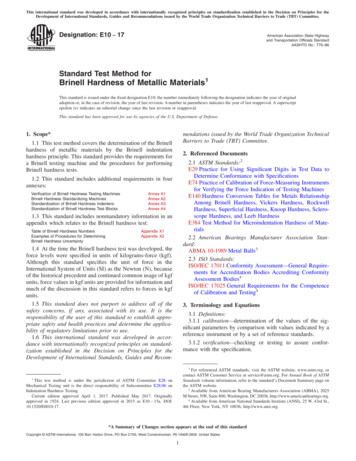
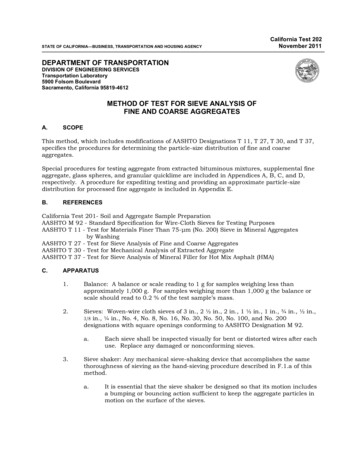
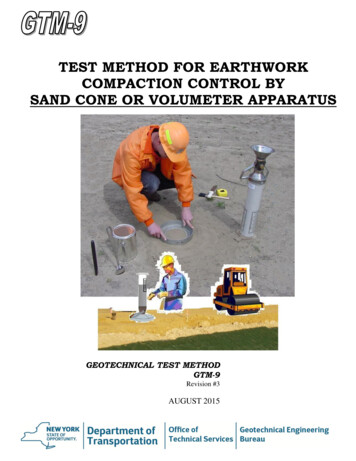
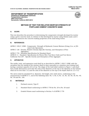
C 900 – 06given concrete placement in a structural element. The measured pullout strength is indicative of the strength of concretewithin the region represented by the conic frustum defined bythe insert head and bearing ring. For typical surface installations, pullout strengths are indicative of the quality of the outerzone of concrete members and can be of benefit in evaluatingthe cover zone of reinforced concrete members.4.4 Cast-in-place inserts require that their locations in thestructure be planned in advance of concrete placement. Postinstalled inserts can be placed at any desired location in thestructure provided the requirements of 6.1 are satisfied.4.5 This test method is not applicable to other types ofpost-installed tests that, if tested to failure, do not involve thesame failure mechanism and do not produce the same conicfrustum as the cast-in-place test described in this test method(16).5. Apparatus5.1 The apparatus requires three basic sub-systems: a pullout insert, a loading system, and a load-measuring system(Note 2). For post-installed inserts, additional equipmentincludes a core drill, a grinding wheel to prepare a flat bearingsurface, a milling tool to undercut a groove to engage theinsert, and an expansion tool to expand the insert into thegroove.NOTE 2—A center-pull hydraulic jack with a pressure gauge calibratedaccording to Annex A1 and a bearing ring have been used satisfactorily.5.1.1 Cast-in-place inserts shall be made of metal that doesnot react with cement. The insert shall consist of a cylindricalhead and a shaft to fix embedment depth. The shaft shall beattached firmly to the center of the head (see Fig. 1). The insertFIG. 1shaft shall be threaded to the insert head so that it can beremoved and replaced by a stronger shaft to pullout the insert,or it shall be an integral part of the insert and also function asthe pullout shaft. Metal components of cast-in-place inserts andattachment hardware shall be of similar material to preventgalvanic corrosion. Post-installed inserts shall be designed sothat they will fit into the drilled holes, and can be expandedsubsequently to fit into the grooves that are undercut at apredetermined depth (see Fig. 2).NOTE 3—A successful post-installed system uses a split ring that iscoiled to fit into the core hole and then expanded into the groove.5.1.2 The loading system shall consist of a bearing ring tobe placed against the hardened concrete surface (see Figs. 1and 2) and a loading apparatus with the necessary loadmeasuring devices that can be readily attached to the pulloutshaft.5.1.3 The test apparatus shall include centering features toensure that the bearing ring is concentric with the insert, andthat the applied load is axial to the pullout shaft, perpendicularto the bearing ring, and uniform on the bearing ring.5.2 Equipment dimensions shall be determined as follows(see Fig. 1):5.2.1 The diameter of the insert head (d2) is the basis fordefining the test geometry. The thickness of the insert head andthe yield strength of the metal shall be sufficient to preventyielding of the insert during test. The sides of the insert headshall be smooth (see Note 5). The insert head diameter shall begreater than or equal to 2 3 of the nominal maximum size ofaggregate.NOTE 4—Typical insert diameters are 25 and 30 mm, but largerSchematic Cross Section of Cast-in-Place Pullout Test2Copyright by ASTM Int'l (all rights reserved); Mon Aug 13 16:22:50 EDT 2007Downloaded/printed byMariana Lara (Germann Instruments, Inc.) pursuant to License Agreement. No further reproductions authorized.
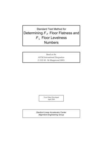
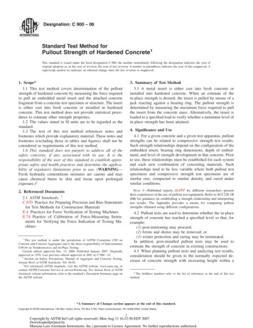
C 900 – 06FIG. 2 Schematic of Procedure for Post-Installed Pullout Testdiameters have been used (1, 3). Tests (15) have shown that nominalmaximum aggregate sizes up to 1.5 times the head diameter do not havesignificant effects on the strength relationships. Larger aggregate sizesmay result in increased scatter of the test results because the large particlescan interfere with normal pullout of the conic frustum.NOTE 5—Cast-in–place inserts may be coated with a release agent tominimize bonding with the concrete, and they may be tapered to minimizeside friction during testing. The insert head should be provided with themeans, such as a notch, to prevent rotation in the concrete if the insertshaft has to be removed prior to performing the test. As a furtherprecaution against rotation of the insert head, all threaded hardware shouldbe checked prior to installation to ensure that it is free-turning and can beeasily removed. A thread-lock compound is recommended to preventloosening of the insert head from the shaft during installation and duringvibration of the surrounding concrete.5.2.2 For cast-in–place inserts, the length of the pulloutinsert shaft shall be such that the distance from the insert headto the concrete surface (h) equals the diameter of the inserthead (d2). The diameter of the insert shaft at the head (d1) shallnot exceed 0.60 d2.5.2.3 For post-installed inserts, the groove to accept theexpandable insert shall be cut so that the distance between thebearing surface of the groove and concrete surface equals theinsert diameter after expansion (d2). The difference betweenthe diameters of the undercut groove (d2) and the core hole (d1)shall be sufficient to prevent localized failure and ensure that aconic frustum of concrete is extracted during the test (see Note6). The expanded insert shall bear uniformly on the entirebearing area of the groove.NOTE 6—A core hole diameter of 18 mm and an undercut groovediameter of 25 mm have been used successfully.5.2.4 The bearing ring shall have an inside diameter (d3) of2.0 to 2.4 times the insert head diameter (d2), and shall have anoutside diameter (d4) of at least 1.25 times the inside diameter.The thickness of the ring (t) shall be at least 0.4 times thepullout insert head diameter.3Copyright by ASTM Int'l (all rights reserved); Mon Aug 13 16:22:50 EDT 2007Downloaded/printed byMariana Lara (Germann Instruments, Inc.) pursuant to License Agreement. No further reproductions authorized.
C 900 – 065.2.5 Tolerances for dimensions of the pullout test inserts,bearing ring and embedment depth shall be 62 % within agiven system.NOTE 7—The limits for dimensions and configurations for pullout testinserts and apparatus are intended to accommodate various systems.5.2.6 The loading apparatus shall have sufficient capacity toprovide the loading rate prescribed in 7.4 and exceed themaximum load expected.NOTE 8—Hydraulic pumps that permit continuous loading may givemore uniform test results than pumps that apply load intermittently.5.2.7 The gauge to measure the pullout force shall have aleast division not larger than 5 % of the minimum value in theintended range of use.5.2.8 The force gauge shall have a maximum value indicator that preserves the value of the maximum load duringtesting.5.2.9 Pullout apparatus shall be calibrated in accordancewith Annex A1 at least once a year and after all repairs.Calibrate the pullout apparatus using a testing machine verifiedin accordance with Practices E 4 or a Class A load cell asdefined in Practice E 74. The indicated pullout force based onthe calibration relationship shall be within 62 % of the forcemeasured by the testing machine or load cell.proper location prior to concrete placement. All inserts shall beembedded to the same depth. The axis of each shaft shall beperpendicular to the formed surface.7.1.2 Alternatively, when instructed by the specifier of tests,manually place inserts into unformed horizontal concretesurfaces. The inserts shall be embedded into the fresh concreteby means that ensure a uniform embedment depth and a planesurface perpendicular to the axis of the insert shaft. Installationof inserts shall be performed or supervised by personnel trainedby the manufacturer or manufacturer’s representative.NOTE 11—Experience indicates that pullout strengths are of lowervalue and more variable for manually-placed surface inserts than forinserts attached to formwork (12).6. Sampling6.1 Pullout test locations shall be separated so that the clearspacing between inserts is at least seven times the pullout inserthead diameter. Clear spacing between the inserts and the edgesof the concrete shall be at least 3.5 times the head diameter.Inserts shall be placed so that reinforcement is outside theexpected conical failure surface by more than one bar diameter,or the maximum size of aggregate, whichever is greater.7.1.3 When pullout strength of the concrete is to be measured, remove all hardware used for securing the pullout insertsin position. Before mounting the loading system, remove anydebris or surface abnormalities to ensure a flat bearing surfacethat is perpendicular to the axis of the insert.7.2 Post-Installed Inserts:7.2.1 The selected test surface shall be flat to provide asuitable working surface for drilling the core and undercuttingthe groove. Drill a core hole perpendicula
2.1 ASTM Standards: 3 C 670 Practice for Preparing Precision and Bias Statements for Test Methods for Construction Materials E4Practices for Force Verification of Testing Machines E74Practice of Calibration of Force-Measuring Instru-ments for Verifying the Force Indication of Testing Ma-chines 3. Summary of Test Method 3.1 A metal insert is either cast into fresh concrete or installed into .