Transcription
Fundamentals of Vehicle DynamicsME5670Lecture 1-2Thomas Gillespie, “Fundamentals of Vehicle Dynamics”, SAE, 1992.http://www.me.utexas.edu/ irbhayAgarwal/four-wheel-steering-systemClass timingMonday: 14:30 Hrs – 16:00 HrsThursday: 16:30 Hrs – 17:30 Hrs
FBD
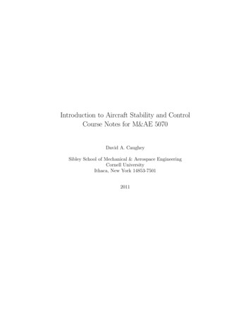
Free Body Diagram1. Vehicle fixed co-ordinate system:1. Earth fixed co-ordinate system:It is defined with reference to aright-hand orthogonal coordinatesystem which originates at CGand travels with the vehicleVehicle altitude and trajectorythrough the course of a maneuverare defined with respect to a righthand orthogonal axis system fixedon the earth.x – forwardy- lateralz- downwardp- roll velocityq- pitch velocityR – yaw velocityX – Forward travelY - Travel to the rightZ - Vertical travel ( downward)𝜓 - Heading angle𝜈 - Course angle𝛽 – Sideslip angle
Physical Quantities1. Euler angles:The vehicle fixed co-ordinate system is related to the earth fixed co-ordinate systemthrough the Euler angles.Euler angles are defined the by the sequence of three angular rotations- Beginning with the earth fixed system,the axis system is first rotated about the z axis (yaw)- It then rotates about the y-axis (pitch)- Finally, it rotate about the x-axis (roll) to line up with the vehicle fixed co-ordinatesystem.The order of the rotation is strictly adhered to get the resultant altitude2. Forces and moments:𝐹𝑥𝐹𝑧 𝑇𝑦Forces and moments are normally defined as they act on the vehicle.The positive sign of longitudinal, vertical and moment in that plane is given by3. Equilibrium condition:- Translational systems: 𝐹𝑥 𝑀𝑎𝑥 ;- Rotational systems:𝑇𝑦 𝐼𝑦𝑦 𝛼𝑦𝐹𝑧 𝑀𝑎𝑧
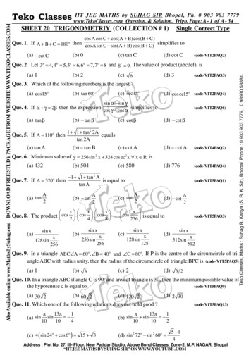
Dynamic Axle Loads1. Dynamic axle loads on a vehicle under arbitrary conditionIt is an important step in analysis of acceleration and braking performance becausethe axle loads determine the tractive effort obtainable at each axle.- acceleration- gradeability- maximum speedForces:W mg weight @ C.G.𝑊𝑓 Weight @front wheel𝑊𝑟 Weight @rear wheel𝐹𝑥𝑓 Traction force at front𝐹𝑥𝑟 Traction force at rear𝑅𝑥𝑓 Rolling resistance at front𝑅𝑥𝑟 Rolling resistance at rear𝐷𝐴 Aerodynamic load acting on the body at ℎ𝑎𝑅ℎ𝑧 Vertical load under towing condition𝑅ℎ𝑥 Longitudnal load under towing condition
Computing Dynamic Axle LoadsLoad carried on each axle will consist of a static component, plus load transferred fromfront to rear due to the other forces acting on the vehicle.Load on the front axle is found by taking net moment about the point A under the rear tiresUnder no acceleration in pitch and taking clockwise direction as positive:𝑊𝑓 𝐿 𝐷𝐴 ℎ𝑎 𝑊𝑎 ℎ 𝑅ℎ𝑥 ℎℎ 𝑅ℎ𝑧 𝑑ℎ 𝑊ℎ sin Θ 𝑊𝑐 cos Θ 0𝑔 𝑥For uphill altitude: Θ veFor downhill altitude: Θ -ve𝑊𝑓 can be obtained by solving the above equationSimilarly, 𝑊𝑟 can be obtained by taking the moment about B under the front wheel.
Axle Load under Different Conditions1. Static loads on Level Ground: When the vehicle sits statically on level ground. Θ 0; 𝑅ℎ𝑥 0; 𝑅ℎ𝑧 0; 𝑎𝑥 0; 𝐷𝐴 0Axle loads:2. Loads on Grades: The influence of grade on axle loads.Grade is defined as the “rise” over the “run”.The ratio of rise over the run is the tangent of the grade angle ΘThe common grades on interstate highways are limited to 4%On primary and secondary roads, they are limited to 10-12 %For small grade angle: sin Θ Θ and cos Θ 1Axle loads:Positive grade causes load to be transferred from the front to the rear axle.
Absolute Motion of a Particle Consider two frames of reference, a fixed frame XY and a rotating frame Oxy withangular velocity 𝜔 Let P be a particle moving the plane of the figure and having position vector r w.r.t.both the frames, however, its rate of change will depend on the selected frame ofreference. Position Velocity Acceleration For any vector A expressed w.r.t. arotating frame, its absolute changeis given byusingwe get
Example
Example Velocity diagram at different wheels of a given configuration Under the condition of no side forces on the wheels
Example If the given velocities are prescribed w.r.t. the earth co-ordinate system Under the condition of no side forces on the wheels
Practice Problem1. Find out the velocity components at each wheel. Also mention the condition for nosideways force on each wheel for the following vehicle carrying a trailer. Assumerequired physical quantity.
Equation of Motion For a rigid body as shown in figure below, lets define the body fixed co-ordinate asshown belowEquation of motion for 6 DOF (3 trans. And 3 rot.)
Equation of Motion State space for of the equationsThe terms which are not eligible canbe neglected Example: Reduce the 6 DOFsystem to 1 DOF for the followingproblem
Solution Assuming no pitch, no roll, no yaw
ExampleFind the weight distribution in a three-wheeled vehicle on level ground under static conditionTaking moment about R-R axisTaking moment about C-C axisTaking moment about F-F axisSolving for the rear axle forcesand
ExampleFind the deceleration which would cause the tipping condition about the front wheel A?Solution: Tipping at the front wheel 𝑁𝐵 , 𝐹𝐵0𝑀𝐴 𝑚𝑎 𝑑𝑚𝑔 25 cos 100 36 sin 100 𝑚𝑎 (36)FBD𝑎 0.510𝑔Deceleration of more than 0.510g will lead toTipping condition
Practice Problem 2Generate the animation for the path of a moving vehicle?
Importance of Sliding and Rolling Friction
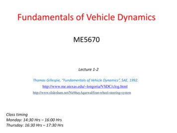
Sliding and Rolling FrictionSliding: Concept of static and kinetic (sliding friction)1. Dry friction occurs between the contacting surfaces of bodies whenthere is no lubricating fluid.2. Assumptions Rough horizontal surface which is no n-rigid or deformable Moving block having weight W is considered to be rigid Block is pulled by a horizontal pulling load PMicroscopic observation!Block weight WNormal force 𝑁𝑛Pulling load PFrictional force 𝐹𝑛Normal force andFrictional force arenon-uniform
Friction in a Nutshell F is a static frictional force if equilibrium is maintained. F is a limiting static frictional force Fs when it reaches amaximum value needed to maintain static equilibrium. F is a kinetic frictional force Fk when sliding occurs atthe contacting surfaces.
Force Analysis of Rolling Body Resultant of distributed normal force To keep the cylinder in equilibrium, all the forces must be concurrent. Resultant force will pass through the center and making an angleof ɵ with vertical Taking a moment about A, we get𝑊𝑎 𝑃𝑟 cos 𝜃Assuming small ɵ, cos (ɵ) 1𝑊𝑎𝑊𝑎 𝑃𝑟𝑟The distance a is termed as the coefficients of rolling resistancehaving the dimension of length.𝑃 Resisting torque:𝑇 𝑁𝑎
ExamplesExample: Wheel being pulled in pure rollA homogeneous wheel of radius R and mass m is initially at rest on a rough horizontalsurface. An external force F is applied at the top rim of the wheel as shown. Assuming thewheel rolls without sliding, find the magnitude and direction of the static friction forceSolution: Assuming static force, we getSince the cylinder rolls without slidingSince, F is less than Fs, slip condition is valid. However, the sign should be opposite
ExamplesExample: Wheel rolling down the incline with frictionA homogeneous wheel of radius R and mass m moves down an incline with inclination 𝛼.Find the angle 𝛼 for which the wheel moves without sliding (or skidding).Solution: When the wheel rolls without sliding (or slip),Equations of motion are:If the wheel rolls without slip, we also haveTaking
Practice ProblemExample: Wheel rolling down the incline with frictionA homogeneous wheel of radius R and mass m moves down an incline with inclination 𝛼.Find the angle 𝛼 for which the wheel moves without sliding (or skidding).Solution: When the wheel rolls without sliding (or slip),Equations of motion are:If the wheel rolls without slip, we also haveTaking
Practice ProblemExample : Show that when the wheel rolls down the incline with sliding, x Example Solving for acceleration of powered mower for a given friction
Free Body Diagram 1. Vehicle fixed co-ordinate system: It is defined with reference to a right-hand orthogonal coordinate system which originates at CG and travels with the vehicle x – forward y- lateral z- downward p- roll velocity q- pitch velocity R – yaw velocity 1. Earth