Transcription
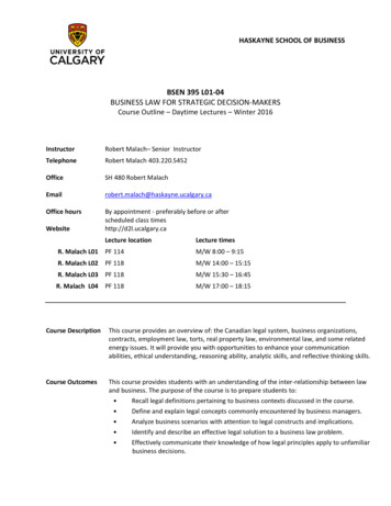
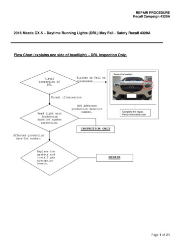
REPAIR PROCEDURERecall Campaign 4320A2016 Mazda CX-5 – Daytime Running Lights (DRL) May Fail - Safety Recall 4320AFlow Chart (explains one side of headlight) – DRL Inspection Only.Complete the repair.Perform the other side.
REPAIR PROCEDURERecall Campaign 4320A1. VEHICLE INSPECTION PROCEDUREVerify that the vehicle is within the following ranges:2016 Model Year Mazda CX-5 vehicles, equipped with LED Daytime Running Light (DRL)ModelSubject VIN range2016 CX-5JM3 KE**** G0 600017 – 751326SubjectproductiondaterangeFrom November 3, 2014 throughDecember 7, 2015The asterisk symbol “*” can be any letter or number.- If the vehicle is within the above ranges, proceed to Visual and Production dateInspection and Repair Procedure- If the vehicle is not within the above ranges, return vehicle to the customer or inventory.Perform a Warranty Vehicle Inquiry using your eMDCS System and inspect vehicle forCampaign Label Recall 4320A attached to the vehicle’s hood or bulkhead. Refer to eMDCSSystem - Warranty Vehicle Inquiry Results table below.NOTE:Be sure to verify Recall number as the vehicle may have multiple Recall labels.
REPAIR PROCEDURERecall Campaign 4320AeMDCS System - Warranty Vehicle Inquiry Results:If eMDCS displays:Campaign Label is:Action to perform:RECALL 4320A OPENPresentEmail Dealer Recall Help or ContactWarranty Hotline at (877) 727-6626option 3 toupdate vehicle history.Proceed to “REPAIR INSPECTIONand PROCEDURES”.Return vehicle to inventory or customer.Not presentRECALL 4320A CLOSEDPresentNot presentRECALL 4320A IS NOTPRESENTDoes not applyProceed to “3. CAMPAIGN LABELINSTALLATION”.Recall does not apply to this vehicle.Return vehicle toinventory or customer.Part /Tool informationNameGASKET KIT(PN: KAYL-51-0A2)Soft shop ragsPick toolRuler or small screwdriverLength of wire, stringDetailBlack gasketQuantity4Gas absorption sheet (Forabsorption sulfur released fromgray gasket remaining in the frontcombination light housing)For prevent scratchesFor Gasket installationForgasabsorptionsheetinstallationFor gasket installation and Gasabsorption sheet installation4Image111N/AN/AN/A1N/A
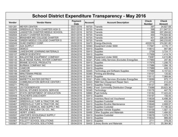
REPAIR PROCEDURERecall Campaign 4320ATechnical guideCheck before repairing the affected vehicle.AFS** Front imageBack imageYes(Equipped)Type BLow beamPosition lightAFS** Adaptive Front Lighting system which enhances the range of visibility when the headlights are turnedon by pointing the optical axis of the headlights in the direction in which the vehicle is advancing accordingto the steering operation. The swivel actuator constantly detects the headlight swivel angle from the hallsensor built into the actuator, and inputs the swivel angle to the AFS control module via LIN communication.
REPAIR PROCEDURERecall Campaign 4320AA. VISUAL INSPECTION1.2.Park the vehicle and turn on the engine.Turn on the low beam.Check the illumination of the DRL position lighting and determine if they are lighting up and notflickering. (Marked by yellow area with shown the image)For more detail, refer to inspection chartbelow.OK - DRL is illuminated.Not OK – DRL is not illuminated or only partiallyilluminated. (Low beam functions normally)Judgement-If both Daytime Running Lamp (DRL) does not light up or the DRL is flickering, replace the bothheadlight assemblies and complete the repair.--If either Daytime Running Lamp (DRL) does not light up or the DRL is flickering, replace theaffected headlight assembly and go to the next step, B. (Inspect working Head Light productiondate and lot number)If both Daytime Running Lamp (DRL) light up, and are not flickering go to next step B.-(Inspect working Head Light production date and lot number)
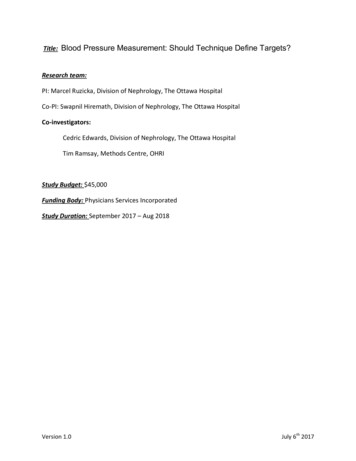
REPAIR PROCEDURERecall Campaign 4320AB. Head Light Production Date Inspection1.2.Open the hood.Check the production date by confirming information sticker or printed lot number for both headlights. (These images are for example of right side of head light. You can inspect the production datewithout removing the headlamps )①Production date②Lot numberProduction dateinspection① Production date(White sticker on middleinformation)② Lot number (Printed by white letter)Examples※Example ImageConversion tableRead the number and separate ayear, month, date.※Example ImageAlign the alphabet to Year and Month.*Date April 5th, 2016*Date April 5, 2016Affected number (date)20141001DM01to EN20October 1st, 2014 to November 20, 201520151120October 1st, 2014 to November 20,2015Judgement- If both headlamp assemblies are not in the affected production date or lot number range, the repair iscomplete. Submit for inspection to close the recall.-If one or both of the headlamp assemblies are in the affected production date or lot number inrange of the headlight, remove the affected head light(s) and replace the gasket with new oneand install the gas absorption sheet. Go to step C.
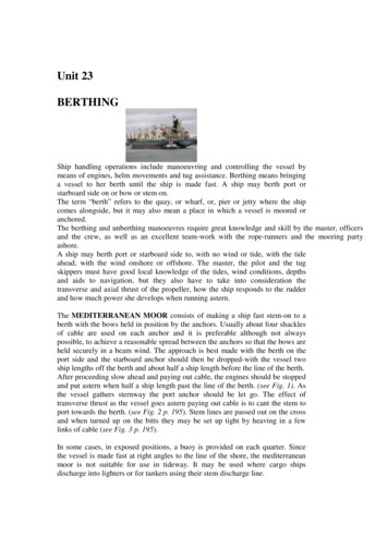
REPAIR PROCEDURERecall Campaign 4320AC. FRONT BUMPER REMOVAL/INSTALLATIONCaution Affix the protective tape to the position (vehicle body side) shown in the figure to prevent scratches anddamage.1. Disconnect the negative battery cable. (See NEGATIVE BATTERY CABLE DISCONNECTION/CONNECTION[SKYACTIV-G 2.5].) (See NEGATIVE BATTERY CABLE DISCONNECTION/CONNECTION2. Remove fasteners A.
REPAIR PROCEDURERecall Campaign 4320A3.Pull the front over fender in the direction of the arrow shown in the figure, set the front over fender out of the waywhile detaching clips B.Caution After removing clips B, insert a rag between the front fender panel and the front over fender to prevent thefront fender panel and clips B from being damaged.4.Remove screws C.5.Remove screws D.6.7.Remove fasteners F.Remove the seal board upper. (See SEAL BOARD UPPER REMOVAL/INSTALLATION.)Remove fasteners G.8.
REPAIR PROCEDURERecall Campaign 4320A9. Remove screws H.10. Pull the front bumper in the direction of the arrow (1) shown in the figure, then remove tabsCaution The front bumper and front bumper slider are engaged firmly. If they are disengaged forcibly the bumpercould fall and be damaged. Perform the servicing carefully when disengaging the front bumper from thefront bumper slider. When disengaging the front bumper from the front bumper slider, the front bumper could fall and bedamaged. Support the front bumper so that it does not fall.
REPAIR PROCEDURERecall Campaign 4320A
REPAIR PROCEDURERecall Campaign 4320A11. Remove the front bumper from the front bumper slider.12. Pull the front bumper in the direction of the arrow (2) shown in the figure and remove it while detaching guidesG.13. Disconnect the front fog light connector. (with front fog lights)14. Disconnect the front ultrasonic sensor connector. (with parking sensor system)Caution After removing front bumper, it may hit the front over fender and cause a damage and/or injury.Perform the following procedure to prevent the front over fender from being damaged.— Fix the front over fender and front fender panel with protective tape.
REPAIR PROCEDURERecall Campaign 4320AFRONT COMBINATION LIGHT REMOVAL/INSTALLATIONWarning Incorrect servicing of the discharge headlights could result in electrical shock. Before servicing thedischarge headlights, always refer to the service warnings. (See DISCHARGE HEADLIGHT SERVICEWARNINGS.)Note Fogging or condensation on the inside of the front combination lights may occur due to a natural phenomenonoccurring as a result of a temperature difference between the interior and exterior of the combination lights. However,it has no effect on the light performance because the temperature inside the front combination lights rises afterilluminating the headlights or a period of time has elapsed.1.Disconnect the connector.2.While pressing the clip tab in the direction of the arrows (1) shown in the figure, press the clip in the direction ofthe arrow (2) shown in the figure to detach the clip tab and front combination light (LH of discharge type).Remove the clip (LH of discharge type).3.
REPAIR PROCEDURERecall Campaign 4320A4.To prevent scratches or damage, affix protective tape to the position shown in the figure.Caution When the front combination light is removed from the body, perform the procedure after affixing protectivetape to the body. Otherwise, the body could interfere with the front combination light and cause scratchingor damage to the body.5.Remove the bolts and the fastener6.Pull the front combination light in the direction of the arrow shown in the figure and pull out the front combinationlight pin from the body.7.Remove the front combination light and proceed to Step D. Gasket replacement procedure.
REPAIR PROCEDURERecall Campaign 4320AD. Gasket replacement procedureConnector of headlight.A:Connector AB:Connector B1.-Replace the gaskets with the new black supplied gaskets of connector A and connector B and installthe two gas absorption sheets.Note: You may find a black gasket from a prior repair at connector B. Replace it anyway. Install gasabsorption sheet at connector B. Go to gas absorption sheet installation procedure.NGOK※Gasket is not two-faced.In order to easily reference locking/unlocking the connector, ①Make sure it is fully locked position (fullyturned left and stopped position) then ②Mark before removing.
REPAIR PROCEDURERecall Campaign 4320A2.Thread a piece of thin spare wire or string tie through the locking tab of the connector*Prevents the headlamp connecter from falling into the headlamp assembly (Connector B)Caution: Be careful not to damage the headlight lens (scratch etc ) or deform the terminal.-Thread a piece of thin spare wire or string tie through the locking tab of the connector.Junk Wire-Unlock the connector from the headlamp and make room between housing and connector to allow forthe removal of the O ring. Recommend watching video B and replacing that O ring first along withinstalling the gas absorption sheet. It is the easier of the two O rings. Then watch video A andreplace connector A O ring. It will be more difficult as the connector cannot be turned 90degrees as shown in the connector B photos below.-Using a pick tool, hook and pull the gasket off of the connector and out of the headlamp.Connector A3.Install the gasket with new one (black one). Thread the new gasket onto the spare wire or string.
REPAIR PROCEDURERecall Campaign 4320A-Push the O ring gasket into the four hooks at the bottom of the connector.HookSingle parts image-Note Connector A will not drop down far enough to turn 90 degrees. This O ring has limitedroom and visibility. Watch Video A②①① OK: Gasket has seated.② NG: Gasket is not seated on the hook.4.Pull the wire and remove from connector. Lock the connector shown the image below.①① OK: Fits on rib protrusion.
REPAIR PROCEDURERecall Campaign 4320A5. Replace O ring for connector B.Caution: Be careful not to damage the headlight lens (scratch etc ) or deform the terminal.Junk Wire-Unlock and make a gap between housing and connector.-Use a pick tool, pull the gasket toward the outside.Pick up tool6.Install the gasket with new one (black one). Thread the new gasket onto the spare wire or string.
REPAIR PROCEDURERecall Campaign 4320A-Push the O ring gasket into the four hooks at the bottom of the connector.HookSingle parts image②①① OK: Gasket has seated.② NG: Gasket comes out from the hook.7.Leave the wire at connector B for the next repair8.Go to Step E Gas absorption sheet installation procedure.
REPAIR PROCEDURERecall Campaign 4320AE. Gas absorption sheet installation procedure. Watch Video.1.2.3.Prepare a gas absorption sheet and use your finger, or tweezer, short ruler to install.Peel off the adhesive tape back of gas absorption sheet.Caution: Do not break the ply formation of the gas absorption sheet.Install gas absorption sheet (2 pieces per one side) inside the connector hole.
REPAIR PROCEDURERecall Campaign 4320A※Example image of cut model.After installation.※Image of left side headlight.After installation.Sheet (Qty 1)Sheet (Qty 1)4.5.Re-install connector B.Make sure all connector is locked. (There is marked where the lock position at yellow circle.)①① OK: Fits on rib protrusion.6.7.8.9.10.11.Remove the spare wire or string.Reverse order of removal.Repair other headlamp if necessary. Go back to Step DInstall the head light(s) with front bumper.Check the headlight aiming.Go to campaign label installation
REPAIR PROCEDURERecall Campaign 4320AF. CAMPAIGN LABEL INSTALLATION1.Fill out a blue “Campaign Label” (9999-95-065A-06) with Campaign No: “4320A”, your dealer code,today’s date.2.Affix it to the hood or bulkhead as shown:3.Return the vehicle to customer.
2016 Model Year Mazda CX-5 vehicles, equipped with LED Daytime Running Light (DRL) Model Subject VIN range Subject production date range 2016 CX-5 JM3 KE**** G0 600017