Transcription
HandbookPneumatic Application& Reference HandbookCv Setting a new standard for: Useful Equations Application Examples Pneumatic Circuits Conversion TablesQ * SG P
Bimba Manufacturing Company is pleased to provide this Pneumatic Application andReference Handbook. It contains helpful information regarding fluid power applicationsolutions. We hope you find the reference helpful.Bimba Manufacturing CompanyBimba Manufacturing is a forward-thinking innovator of actuation technology, specializingin providing cutting-edge solutions to engineering challenges. Since introducing theround line stainless steel body cylinder over five decades ago, Bimba has expanded itscapabilities to include an extensive line of industry-leading air cylinders, rotary actuators,linear thrusters, rodless cylinders, flow controls and position-sensing cylinders.The driving force behind these products is a commitment to customer satisfaction. It's adedication to deliver more solutions, in more sizes, for more applications. Bimba's goal isto exceed performance and longevity expectations. To demonstrate this company-widepromise to provide quality products, Bimba maintains an ISO 9001 certification. The ISOstandard provides a uniform framework for quality assurance that is recognized worldwide.With a large inventory of standard catalog products for quick delivery, manufacturingfacilities in several locations and an international network of stocking distributors, workingwith Bimba means fast, on-time delivery and superior service.TRD provides a variety of high-qualityNFPA-interchangeable cylinders andspecialized cylinders while setting thebenchmark in the industry for on-timedelivery.Mead is a leader in the design and development of valves, cylinders, and pneumatic components for the industrialautomation market.In addition to a broad line of standardcatalog products, nearly half of Bimba'sbusiness consists of custom and semicustom products designed for specificcustomers with unique applications.-2-
Table of ContentsSection I5-145-678910-14ValvesUnderstanding Circuit SymbolsCV DefinedPneumatic Valve SizingValve SelectionFrequently Asked QuestionsSection atic Actuator TypesSize SelectionCylinder MountingCylinder OptionsAmbient ConditionsPiston Rod StrengthPneumatic Cylinder ForceAir Cylinder SpeedAir Consumption RatesFrequently Asked QuestionsSection III30-32303031313132Position SensingPosition Feedback CylindersClosed Loop ControllersSwitch TechnologyProximity SwitchesSinking and SourcingSwitch Hysteresis and the OperatingWindowSwitch Troubleshooting32Section IV33-37333333333434353637Section V38CircuitsBasic Control CircuitsAir CircuitsTiming CircuitsDual Signal CircuitAdvanced Control CircuitsTwo Valves for Three-Position FunctionTwo-Hand Extend One-Hand RetractTwo-Hand Extend Two-Hand RetractTwo-Hand Extend with Automatic ReturnAir Filtration, Regulation, and Lubrication-3-
Section VI39-42393940414142ChartsPneumatic Pipe SizePneumatic Pressure LossAir Flow Loss Through PipesPressure Loss Through PipesFriction of Air in HoseVacuum Flow Through OrificesSection VII43-4643-444545-46ConversionsDecimal EquivalentsEnglish / Metric ConversionsEnglish / Metric Interchange Tables:TorqueLengthAreaVolumeForceMassUnit PressureVelocityThe information presented should be used for reference only. Users should verify the accuracy of this information before using in their applications. Bimba is not held responsible toany inaccuracies or mis-application of the information provided.-4-
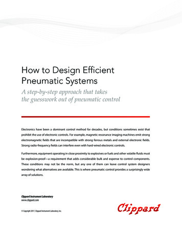
Section I: ValvesUnderstanding Circuit SymbolsDirectional air control valves are the building blocks of pneumatic control. Symbols representingthese valves provide a wealth of information about the valve it represents. Symbols show the methods of actuation, the number of positions, the flow paths and the number of ports. Here is a briefbreakdown of how to read a symbol:2 Position, Lever Actuated, Spring Return ValveEvery symbol has three parts (see figure to right). The Left and RightActuators are the pieces which cause the valve to shift from one position toanother. The Position and Flow Boxes indicate how the valve functions.Every valve has at least two positions and each position has one or moreflow paths.LeftPosition & FlowRightActuatorBoxesActuatorWhen the Lever is not activated, the Spring Actuator (right side) is in controlof the valve; the box next to the actuator is the current flow path. When theLever is actuated, the box next to the Lever is in control of the valve. Each position occurs when the attached actuator is in control of the valve (Box next to the actuator). A valve can only be in one “Position” at a given time.The number of boxes that makes up a valve symbol indicates the number of positions the valvehas. Flow is indicated by the arrows in each box. These arrows represent the flow paths the valvehas when it is in that position (depending upon which actuator has control over the valve at thattime).The number of ports is determined by the number of end points in a given box (only count in onebox per symbol as the other boxes are just showing different states of the same valve). In theexample, there are a total of 5 ports. NOTE: Sometimes a port (such as exhaust) goes directly toatmosphere and there is no port to attach to. To spot this, the actual port line will extend beyond the box, while theports you cannot attach to will not. A Port is blocked with the symbol:Following is a list of symbols and what they mean:Valve Symbols, Flow Paths and PortsActuator Symbols2-Position, 2-Way, 2-PortedManual2-Position, 3-Way, 3-PortedPush ButtonLever2-Position, 4-Way, 4-PortedFoot OperatedMechanical2-Position, 4-Way, 5-PortedSpring3-Position, 4-Way, 4-PortedClosed CenterDetentSolenoid-5-Symbols Continue on Next Page
Section I: ValvesActuator SymbolsLinesInternal PilotMain LineExternal PilotPilot LinePiloted Solenoid withManual OverrideLines CrossingLines JoinedPiloted Solenoid andManual OverrideLines JoinedLever Operated, Spring ReturnSolenoid Operated, Spring ReturnSimple Pneumatic ValvesCheck ValveFlow Control, 1 DirectionRelief Valve-6-
Section I: ValvesCv DefinedQ: What does “CV” mean?A: Literally CV means coefficient of velocity. CV is generally used to compare flows of valves. The higher the CV, the greater the flow.It is sometimes helpful to convert CV into SCFM (Standard Cubic Feet per Minute) and conversely,SCFM into CV. Although CV represents flow capacity at all pressures, SCFM represents flow at aspecific air pressure. Therefore, the following chart relates CV to SCFM at a group of pressures.To obtain SCFM output at a particular pressure, divide the valve CV by the appropriate factor shownbelow.CV to SCFM Conversion Factor TablePSI of Air 0.0192100.0177Example: What is the output in SCFM of a valve with a CV of 0.48 when operated at 100 psi?0.48 (CV) 27 SCFM.0177 (Factor)To convert SCFM into CV, simply reverse the process and multiply the SCFM by the factor.-7-
Section I: ValvesPneumatic Valve SizingTwo methods are shown below to aid in the selection of a pneumatic valve. To account for variouslosses in all pneumatic systems, remember to over-size by at least 25%.Method 1: CalculationThis formula and chart will give the Cv (Valve flow) required for operating a given air cylinder at aspecific time period.Area x Stroke x A x CfCV Time x 29Area π x Radius2 (see table B)Stroke Cylinder Travel (in.)A Pressure Drop Constant (see table A)Cf Compression Factor (see table A)Time In SecondsTable BTable 2"A" Constants for Various Pressure Drops2 psi5 psi10 psi P P 10.0300.0620.0390.029BoreSizeCylinderArea(Sq. 078.3012.5719.6428.2750.2778.54113.10NOTE: Use “A” Constant at 5 psi P for most applications. For critical applications, use “A” at 2 psi P. “A” at 10psi P will save money and mounting space.Method 2: ChartIndex Cv against Bore Size vs. Inches of stroke per second. Assuming 80 psi and P 342685362.003.87.518.937.775.5151302604Cylinder Bore .418.937.775.5
Section I: ValvesValve SelectionQ: How do I select the right valve to control a cylinder?A: There are many factors that contribute to theperformance of a cylinder. Some of these factorsare: quantity and type of fittings leading to the cylinder, tube length and capacity, cylinder operatingload, and air pressure.Rather than attempting to place a value on these, and other contributing factors, it is more practicalto provide valve users with a general guide to valve sizing.The sizing table below relates various Mead air valves to cylinder bore sizes between 3/4" and 6".The cylinder operating speed resulting from the use of each valve at 80 psi is rated in general termsas:“F” for High Speed Operation, “M” for Average Speed Operation, “S” for Slow Speed OperationValve TypeCvCylinderType*Micro-Line0.11SALTV0.18SA, DANova1.00SA, DADura-Matic0.18SA, DADura-Matic0.63SA, DACapsula0.75SA, DACapsula3.17SA, DAFT-1, FC-10.13SA4B-1, 4W-10.48SA, DAFC51, PC510.81SAFT-101, 2011.15SAIsonic V1,V2 0.01-0.05SAIsonic V40.8SA, DAIsonic V30.03-0.11SAIsonic V50.8SA, DACylinder Bore Sizes (inches)3/4F1FFFF1-1/8 1-1/22FFFFFFFFFFMFMFFFFFFFMFFFFFFMFFSF2-1/4 SSMFMFFFMMFFFMM6MMMFMFM*SA Single-Acting Cylinder, DA Double-Acting CylinderWhere no rating is shown, the valve is considered unsuitable for use with that particular bore size. To determine thesuitability of valves not listed in the table, compare the Cv of the unlisted valve with the one nearest it on the tableand use that line for reference.-9-
Section I: ValvesSCFM DefinedQ: What does SCFM mean?A: SCFM means Standard Cubic Feet per Minute. “Standard” is air at sea level and at 70 F.Shuttle ValvesQ: Is there a valve that will direct air coming from either of two sources to a single destination?A: Use a shuttle valve.StackingQ: How may I reduce piping and simplify trouble-shooting when a group ofvalves is used in an application?A: Order your valves stacked to take advantage of a common air inlet,common exhausts, and control centralization.Time DelayQ: Are there valves that allow me to delay a signal in my air circuit?A: Yes, Mead air timers can be used to delay an air signal. Up to twominute normally open or normally closed models are available.Two-Position - vs - Three-PositionQ: What is the difference between two-position and three-position valves?A: In two-position four-way directional valves, the two output ports are always in an opposite mode.When one is receiving inlet air, the other is connected to the exhaust port.When actuated, three-position four-way directional valves function the same as above. However, acenter or “neutral” position is provided that blocks all ports (pressure held), or connects both outputports to the exhausts (pressure released) when the valve is not being actuated.Pressure Held Three-Position ValvesPressure held models are ideal for “inching” operations where you want the cylinder rod to move to adesired position and then hold.Pressure Released Three-Position Valves-10-
Section I: ValvesFive-Ported ValvesQ: What are the advantages of a five-ported four-way valve over a four-ported four-way valve?A: Five-ported valves have separate exhaust ports for each cylinder port. If exhaust silencers withbuilt-in speed controls are used, the speed of the cylinder motion may be individually controlled ineach direction.Also, five-ported valves can function as dual pressure valves where air flows from the exhaust portsto the cylinder and both cylinder ports use the inlet as a common exhaust. Vacuum may also beused in five-ported valves. Both the Mead Nova line and the Capsula line provide five-ported flowpatterns.Flow ControlQ: Are there valves available that provide adjustable control of air flow?A: Mead Dyla-Trol valves perform this function. Also see the “Cylinders;Speed Control” question for application information. Dura-Matic directionalvalves have built-in flow controls. Exhaust silencers typically have built-in needle valves that also provide speed regulation. See the Mead catalog for moreinformation.Flow Patterns, Three-Way and Four-WayQ: What is the difference between a three-way and a four-way valve?A: Three-way valves have one power output and four-way valves have two power outputs.Generally, three-way valves operate single-acting cylinders and four-way valves operate double-acting cylinders. For three-way and four-way valves, see the Mead Catalog MV and LTV valves, respectively.Three-Way Flow Pattern (Normally Closed)Four-Way Flow Pattern (Two Position)For Safer Hand ActuationQ: How may I keep the hands of my employees out of hazardous locations?CSVA: Use two-hand, anti-tiedown devices (Mead CSV).-11-
Section I: ValvesAir - vs - Solenoid ActuationQ: What are the advantages of air actuation over solenoid actuation?A: Solenoid actuation requires the presence of electric switches, wires, and all of the shielding necessary to reduce spark hazard and personal risk.NOTE: The Solenoid Valve shownhere is N2-DCD.Air actuation requires only three-way air pilot valves and tubing. There is no explosion, spark, orshock risk and the components inexpensive.NOTE: The Air Piloted Valve shownhere is the N2-DP. The Three-WayPilot Valves are from the MV series.Detented ValvesQ: What is a “detented” valve and how is it used?A: A detented valve is one that holds its position by some mechanical meanssuch as a spring, ball or cam. Most valves hold their position by means of thenatural friction of the rubber seals. Where natural friction is low, such as in packless valves, or where it is not enough for safety purposes, detented models arerecommended. Also, detents are used to locate the middle position in three position valves. (See the Capsula Valve Section in the Mead Catalog.)Air-To-Electric Signal ConversionQ: Is it possible to convert an air signal into an electrical signal?A: Mead air-to-electric switches, MPE-BZ or MPE-BZE (includes enclosure),will turn an air signal into an electrical signal, which can be wired either normally open or closed.Pressure Piloted - vs - Bleed PilotedQ: What is the difference between pressure piloted valves and bleed piloted valves?A: Pressure piloting and bleed piloting refer to two different modes in which valves may be actuated.Pressure piloting positively actuates directional valves by an external air signal that comes from a remote three-way valve, such as the Micro-Line valve series. Air pressure piloting provides an economical alternative to the use of electric switches and solenoids.NOTE: Valves shown here are from the NovaSeries (Pressure Piloted Directional Valve) andthe MV Series (Three-Way Pilot Valve).Bleed piloting uses internal air from the directional valve to feed the pilot valve. Air flows from the directional valve to the bleed valve. When the bleed valve is actuated, a pressure drop occurs in thedirectional valve pilot section. This causes a differential pressure and valve shift.The main advantage of bleed piloting is that only one line enters the bleed valve. However, if the lineis severed, a shift occurs. Pressure piloting isconsidered more positive and reliable.BLEED VALVE-12-
Section I: ValvesLow Force To ActuateQ: Are there valves available that require an unusually low force to actuate?A: Low-stress valves need only 6-8 oz. of force to initiate a signal. These valves reducestress on worker’s hands. LTV four-way valves operate on a pressure differential basis thatallows them to actuate with very little force.Manual OverridesQ: What are manual overrides in air valves used for?A: Manual overrides permit the user to actuate the directional valves without using the switches orpilot valves that would normally be used. In this way, a circuit may be tested without actually movingthe machine elements.Both Mead Capsula valves and Nova valves are available with manual overrides.Normally Closed - vs - Normally OpenQ: What is the difference between a three-way normally closed valve and a three-way normally openvalve?A: Normally open valves allow air to pass when not actuated. Normally closed valves allow air topass only when they are actuated.Normally Closed Flow PatternNormally Open Flow PatternPanel MountedQ: Are there valves available that fit through “knockouts” in control panels?A: MV three-way valves and LTV four-way valves have threaded mounting stems forpanels.External Air Supply For SolenoidsQ: Under what conditions should an external air supply be used to feed thesolenoids on a directional valve?A: When the air pressure passing through the power section of the valve isinsufficient to shift the spool, when the medium passing through the powersection would be detrimental to the solenoid operator, or where the operating medium could not beexhausted to the atmosphere.-13-
Section I: ValvesPulse TypeQ: When I am using a double air piloted directional valve, how do I get the valve to shift when one ofthe pilots is already being charged?A: Place a Mead impulse relay valve (414B) between the pilot valve and the directional valve on theside that is being rested upon.Sound Suppression, SilencersQ: How do I reduce the noise generated by air exhausting from a valve?A: Use air silencers.-14-
Section II: CylindersPneumatic Actuator TypesRound LineNon-repairable cylinders have a reputation as hardworking, long-lasting, economical performers. Theyare available in a wide range of bore sizes, mounting styles and options. If high side or moment loadsare present in the application, external guiding isrequired.NFPANFPA tie rod cylinders feature a durable, repairabledesign. They are available in a wide range of boresizes and stroke lengths, with a variety of options.CompactWhen space is limited, flat cylinders are a greatsolution. They are available in round, square, nonrotating, dual-power or three-position models.Narrow Profile Air TablesThe narrow profile air table actuator provides precise load guiding and high precision due to therecirculating ball rail above the cylinder bore.Twin BoreTwin bore cylinders have small cross sections andtwo bores for double the force, with smooth operation and no rotation, and a high side load capacity.Guided ThrustersAn integral guiding mechanism from the cylindermanufacturer is a lower cost, immediately availablealternative to home spun guide rails. Guide rodsenable the cylinder to move a heavier load, preventdamage from side loads, and improve end of strokeaccuracy. Extruded versions with the bore integralto the extrusion maintain their side load capacityregardless of changes in stroke.Rodless CylinderRodless magnetically coupled cylinders use a tubesimilar to a round line cylinder. Strong magnets builtinto the piston couple the piston to magnets in thecarriage which slides over the cylinder body. Thisdesign is much shorter than a round line rod typecylinder.-15-
Section II: CylindersRodless SlideBimba's rodless slides are magnetically coupled,and feature built in guides for self-guided motionwith approximately 50% space savings over conventional cylinders. They are designed to handleside and moment loads. These load carrying capabilities can be increased by ordering external shockabsorbers.Rodless Band CylindersLike the rodless magnetically coupled cylinders, theband cylinder saves space by using a carriage thatis coupled to the piston and rides over the body ofthe cylinder. In this case the piston is rigidly coupled to the carriage, and rides inside the bore ofthe body extrusion. As the piston moves, it opensand closes a seal at the top of the cylinder. Theseal works like a zipper, minimizing leakage.Compared to magnetically coupled cylinders, bandtypes leak more, but are not subject to decoupling.Rotary ActuatorsRotary actuators provide rotary motion. There aretwo types of rotary actuators, rack and pinion andvane designs. Rack and pinion designs providegreater rotation, no external or shaft seals, highshaft loading capacity, low friction, low breakaway,and very low leakage. Vane types have no backlash, but rotation is limited to 270 degrees, theshaft seal is a wear point, and the paddle seal creates high friction.Position FeedbackPosition feedback cylinders use sensors inside thecylinder to provide an output voltage proportional tothe stroke. Feedback can be monitored to detectthe presence, absence, position, or size of a partfor real time process control. A closed loop controller can be used with the cylinder. The controllercompares the feedback voltage to a control voltagefrom a PLC and adjusts pressure on either side ofthe piston to move the cylinder precisely into position and hold it there until the control voltagechanges.-16-
Section II: CylindersSize SelectionQ: How do I determine the correct cylinder bore size for my application?A: Follow these four easy steps.1. Weigh your load, including any base or supports, and determine the opposing force F needed tosupport it. Select the appropriate multiplier from the table below based on the angle of inclinationof the load.Angle10 20 30 40 50 60 70 80 90 A0.170.340.500.640.770.870.940.981.0F A x (Weight of load in pounds)2. Increase the force as necessary to achieve the desired speed. Simply multiply F from step (1)above by S from the table below.Speed(inches/second)SUp to 44 to 16Above 161.251.502.00Fs F x S3. Select the air pressure to be supplied to the cylinder. Too high an air pressure will acceleratecylinder wear. Follow the air cylinder manufacturer’s recommendations, and minimize airpressure to extend life.4. Divide Fs from step (2) above by the air pressure in PSI. Then compare your result to the PowerFactor numbers in the table below. Select a Power Factor equal to or greater than your calculated result, then read the corresponding bore size in the bottom row.PF Fs psiPowerFactorBore0.070.150.250.400.605/16 7/16 9/163/47/80.901.21.72.41-1/16 1-1/4 1-1/2 1-3/43.1578.322-1/233-1/412.5 28.346Example: The load is 400 pounds. It will be moved up an incline of 50 . The load must move at 8inches per second. What cylinder bore size is required?1. F 2. Fs 3. PF Fs psi 46280A x (weight of load) .77 x 400 308F x S 308 x 1.5 462 5.8Bore size required is 3 inches.-17-
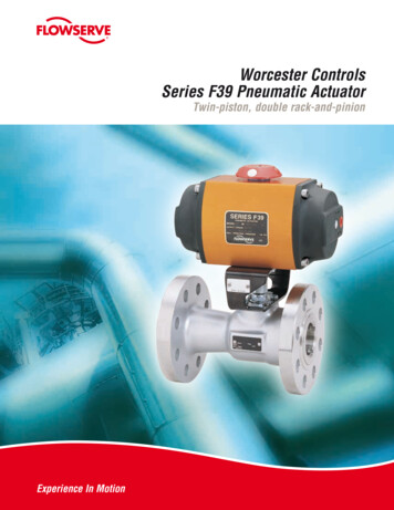
Section II: CylindersCylinder mountingPivot mounting options include the pivot, clevis, and trunnion. They areeffective in eliminating side loads in a single plane. Installation requires a rodeye or rod clevis on the piston rod, and the alignment of all pivot pins in parallel to prevent binding. Long stroke cylinders often need a stop tube or dualpiston to manage bending stresses during extend and retract.PivotTrunnion mounts require pillow blocks or mated bearings as close as possible to the heads to minimize bending stresses. Spherical bearing pillowblocks should never be used in conjunction with trunnion mounts.TrunnionRigid mounting options include side, nose, flange, and face mounts. If the cylinder is not perfectly aligned with the direction of travel of the load, a side load will be introduced that will causewear and shorten cylinder life. In cases of misalignment, use either a commercial rod-end couplerwith built-in axial allowance or a built-in axial take-up in the rod-end.Nose MountNormal air escapeblocked by spearBlock FrontSpear sealTapered spearExhaust portPistonCylinder optionsCushions in either or both ends of the cylinder control decelerationand relieve impact at end of stroke, improving durability.Bumpers are rubber discs that absorb impact and noise at the endof stroke, reducing noise and vibration.AdjustmentneedlePad of airAlternate airescapeCushionAdjustingneedleTapered stainlesssteel needleStop tubes or dual pistons manage side loads by distributing theforces over a larger area of the cylinder.Rod wipers help keep contaminants out of the cylinder by wipingthe rod as it retracts.Flow controls help assure constant, controllable air flow for preciseand consistent speed control regardless of variations in air pressure.Chrome platedbanjo connectorLip seal designAnodizedaluminum stemDry film threadsealantFlow Control-18-
Section II: CylindersAmbient ConditionsThe following environmental conditions will require special cylinders or special materials.zzzzOperating temperature above 200 F (95 C) or below -20 F (-25 C).Extended operation below 0 F (-18 C)Radiation, caustic washdowns, water, saline, dust, and other contaminationInadequate maintenance and lubrication – follow manufacturer's recommendationsPiston Rod StrengthIf subjected to a heavy load, a piston rod may buckle. The following chart suggests minimum roddiameters under various load conditions when the rod is extended and unsupported, and must beused in accordance with the chart’s instructions (see next paragraph). There must be no side loador bend stress at any point along the extending rod.HOW TO USE THE TABLE: Exposed length of rod is shown at the top of the table. This length istypically longer than the stroke length of the cylinder. The vertical scale shows the load on the cylinder and is in English tons (1 ton 2000 lbs.). If the rod and front end of the cylinder barrel are rigidlysupported, then a smaller rod will be sufficient; use the column that is 1/2 the length of the actualpiston rod. If pivot to pivot mounting is used, double the actual length of the exposed rod and utilizethe suggested rod diameter.Figures in body of chart are suggested minimum rod 7-1/21015203040507510015010201/8Exposed Length of Piston Rod -1/43-1/23-3/444-1/256CAUTION: Horizontal or angle mounted cylinders (anything other than vertical) creates a bendstress on the rod when extended, just from the weight of the rod and cylinder itself. Trunnionmounting should be utilized in a position which will balance the cylinder weight when extended.-19-
Section II: CylindersPneumatic Cylinder ForceCylinder forces are shown in pounds for both extension and retraction. Lines in standard type showextension forces, using the full piston area. Piston and rod diameters are in inches. Lines in italictype show retraction forces with various rod sizes. The valves below are theoretical, derived by calculation.Pressures shown across the top of the chart are differential pressures across the two cylinder ports.In practice, the air supply line must supply another 5% of pressure to make up for cylinder loss, andmust supply an estimated 25-50% additional pressure to make up for flow losses in lines and valving so the cylinder will have sufficient travel speed.For all practical purposes, design your system 25% over and above your theoretical /233-1/445681012RodEffec. AreaDiameterSq. 591369048135721319512983
Section II: CylindersAir Cylinder SpeedEstimating cylinder speed is extremely difficult because of the flow losses within the system in piping, fittings, andporting through the valves which are in the air path. Flow losses cause a loss in pressure which directly effect theforce output. To be able to determine the maximum speed of the cylinder, the sum of all flow losses, pressurerequired for the force output and the available inlet pressure must be known. Circuit losses cannot be determinedor calculated accurately. Rules of thumb are relied upon to determine an approximation of air cylinder speed.The first general rule of thumb is choo
Bimba Manufacturing Company is pleased to provide this Pneumatic Application and Reference Handbook. It contains helpful information regarding fluid power application solutions. We hope you find the reference helpful. Bimba Manufacturing Company Bimba Manufacturing is aforwar