Transcription
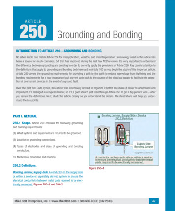
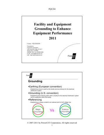
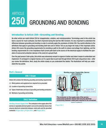
ARTICLE250GROUNDING AND BONDINGIntroduction to Article 250—Grounding and BondingNo other article can match Article 250 for misapplication, violation, and misinterpretation. Terminology used in this article hasbeen a source for much confusion, but that’s improved during the last few NEC revisions. It’s very important to understand thedifference between grounding and bonding in order to correctly apply the provisions of Article 250. Pay careful attention to thedefinitions that apply to grounding and bonding both here and in Article 100 as you begin the study of this important article.Article 250 covers the grounding requirements for providing a path to the earth to reduce overvoltage from lightning, and thebonding requirements for a low‑impedance fault current path back to the source of the electrical supply to facilitate the operation of overcurrent protection devices in the event of a ground fault.Over the past several Code cycles, this article was extensively revised to organize it better and make it easier to understand andimplement. It’s arranged in a logical manner, so it’s a good idea to just read through Article 250 to get a big picture view—afteryou review the definitions. Next, study the article closely so you understand the details. The illustrations will help you understand the key points.Part I. GeneralBonding Jumper, Supply-Side, Service250.2 Definition250.1 ScopeArticle 250 contains the following grounding and bonding requirements:(1) What systems and equipment are required to be grounded.(3) Location of grounding connections.(4) Types of electrodes and sizes of grounding and bonding conductors.SCH 80(5) Methods of grounding and bonding.Supply-SideBonding JumperThe conductor on the supply side of the serviceovercurrent protection device that ensures electricalconductivity between metal parts required to be connected.250.2 DefinitionBonding Jumper, Supply-Side. The conductor on the supply side of theservice or separately derived system overcurrent protection device thatensures electrical conductivity between metal parts and the groundedconductor. }Figure 250–1, }Figure 250–2, and }Figure 250–3Copyright 2017, www.MikeHolt.com}Figure 250–1Mike Holt Enterprises www.MikeHolt.com 888.NEC.CODE (632.2633)55
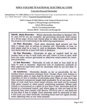
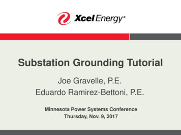
250.4 Grounding and BondingBonding Jumper, Supply-Side, Transformer250.2 DefinitionLegendEGC: Equipment Grounding ConductorGEC: Grounding Electrode ConductorSBJ: System Bonding JumperSSBJ: Supply-Side Bonding JumperN: NeutralElectrical System cal power systems aregrounded (connected to the earth) tolimit the voltage induced by lightning,line surges, or unintentional contactby higher-voltage lines.GECThe conductor on the supply side of the separatelyderived system overcurrent protection device thatensures electrical conductivity between metal partsrequired to be electrically connected.Copyright 2017, www.MikeHolt.comCopyright 2017, www.MikeHolt.com}Figure 250–2}Figure 250–4Bonding Jumper, Supply-Side, SDS, Generator250.2 DefinitionServiceMBJNTransfer Switch Gen. DisconnectNGenerator (SDS)NEGCEGCEGCSBJSSBJEGCSBJGECEGCGEC GECAuthor’s Comment: System grounding helps reduce fires in buildings as well asvoltage stress on electrical insulation, thereby ensuring longerinsulation life for motors, transformers, and other systemcomponents. }Figure 250–5EGCPanelboardElectrical System Grounding250.4(A)(1) CommentNEffective Ground-Fault Current PathEGC: Equipment Grounding ConductorGEC: Grounding Electrode ConductorMBJ: Main Bonding JumperSBJ: System Bonding JumperSSBJ: Supply-Side Bonding JumperThe conductor on the supply side of the SDSovercurrent protection device that ensureselectrical conductivity between metal partsrequired to be electrically connected.LegendEGC: Equipment Grounding ConductorGEC: Grounding Electrode ConductorSBJ: System Bonding JumperSSBJ: Supply-Side Bonding JumperN: NeutralTransformerDisconnectSolidly Grounded SystemTransformerCopyright 2017, www.MikeHolt.comSBJNEGC}Figure 250–3GEC2017CC250.4 Performance Requirementsfor Grounding and Bonding(A) Solidly Grounded Systems.Scan this QR code for a video of Mike explaining this topic; it’sa sample from the DVDs that accompany this textbook.(1) Electrical System Grounding. Electrical power systems are grounded(connected to the earth) to limit the voltage induced by lightning, linesurges, or unintentional contact by higher‑voltage lines. }Figure 250–456NEGCSSBJDisconnectPanelSystem grounding helps reduce fires in buildingsas well as voltage stress on electrical insulation,thereby ensuring longer insulation life for motors,transformers, and other system components.Copyright 2017, www.MikeHolt.com}Figure 250–5Note 1: To limit imposed voltage, the grounding electrode conductors shouldn’t beany longer than necessary and unnecessary bends and loops should be avoided.}Figure 250–6Mike Holt’s Illustrated Guide to Understanding 2017 NEC Requirements for Bonding and Grounding
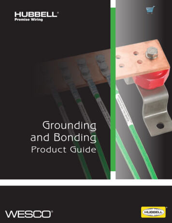
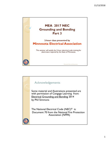
Grounding and Bonding 250.4LegendEGC: Equipment Grounding ConductorGEC: Grounding Electrode ConductorSBJ: System Bonding JumperSSBJ: Supply-Side Bonding JumperN: NeutralTransformerDisconnectEquipment Grounding250.4(A)(2) CommentElectrical System Grounding250.4(A)(1) Note 1TransformerSBJNEGCNEGCSSBJGECDisconnectPanelTo limit imposed voltage, the grounding electrodeconductors shouldn’t be any longer than necessaryand unnecessary bends and loops should be avoided.Failure to ground metal parts can result in high voltage froman indirect lightning strike seeking a path to the earth withinthe building, possibly resulting in a fire and/or electric shock.Copyright 2017, www.MikeHolt.comCopyright 2017, www.MikeHolt.com}Figure 250–6}Figure 250–8Note 2: See NFPA 780, Standard for the Installation of Lightning Protection Systemsfor grounding and bonding of lightning protection systems.Author’s Comment: (2) Equipment Grounding. Metal parts of electrical equipment aregrounded to reduce arcing within the buildings/structures from inducedvoltage from indirect lightning strikes. }Figure 250–7Grounding metal parts helps drain off static electricity chargesbefore flashover potential is reached. Static grounding is oftenused in areas where the discharge (arcing) of the voltagebuildup (static) can cause dangerous or undesirable conditions [500.4 Note 3].(3) Equipment Bonding. Metal parts of electrical raceways, cables,enclosures, and equipment must be connected to the supply sourcevia an effective ground‑fault current path. }Figure 250–9Equipment Grounded to Earth250.4(A)(2)Metal parts of electrical equipmentmust be grounded to reduce arcingwithin the buildings/structures frominduced voltage from indirect lightning.Bonding of Electrical EquipmentLegend250.4(A)(3)EGC: Equipment Grounding ConductorMeterSourceServiceMainPanelGEC: Grounding Electrode ConductorMBJ: Main Bonding JumperN: Neutral ECEffective Ground-FaultCurrent PathCopyright 2017, www.MikeHolt.com}Figure 250–7DANGER: Failure to ground metal parts to earth canresult in induced voltage on metal parts from an indirect lightning strike seeking a path to the earth within thebuilding—possibly resulting in a fire and/or electric shock froma side flash. }Figure 250–8GroundFaultMetal parts of electrical raceways, cables, enclosures,and equipment must be connected to the supply sourcevia an effective ground-fault current path.Copyright 2017, www.MikeHolt.com}Figure 250–9Mike Holt Enterprises www.MikeHolt.com 888.NEC.CODE (632.2633)57
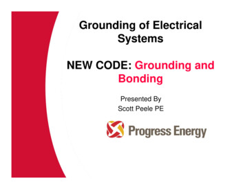
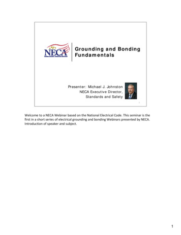
250.4 Grounding and BondingTime-Current Curve20A Inverse Time BreakerAuthor’s Comment: To quickly remove dangerous voltage on metal parts froma ground fault, the effective ground‑fault current path musthave sufficiently low impedance to the source so faultcurrent will quickly rise to a level that will open the branch‑circuit overcurrent protection device. }Figure 250–10Opening an Overcurrent Device200 ft 3 AWG0.05 ohmsLegendEGC: Equipment Grounding ConductorSBJ: System Bonding JumperSSBJ: Supply-Side Bonding Jumper155 Sec150 Sec145 Sec45 Sec40 Sec35 Sec30 Sec25 Sec20 Sec100A FaultClears in 15 Sec5 to 2010 SecSeconds5 Sec40A FaultClears in25 to 150SecondsMaximumUnlatching TimeMinimumUnlatching Time40A 100A120VThe higher the current, the faster the fault clears.Copyright 2017, www.MikeHolt.com}Figure 250–11SBJSSBJ100ADeviceFault Current 583Amps200 ft 8 AWG0.156 ohmsEGCBonding Electrically Conductive Materials250.4(A)(4)120VE 583A 0.206 ohmsZThe 100A overcurrent device quickly opens andremoves dangerous voltage from metal parts.Sprinkler PipingGas PipingCopyright 2017, www.MikeHolt.com}Figure 250–10 The time it takes for an overcurrent protection device to openis dependent on the magnitude of the fault current. A higherfault current value will result in a shorter clearing time for theovercurrent protection device. For example, a 20A overcurrentprotection device with an overload of 40A (two times the 20Arating) takes 25 to 150 seconds to open. The same deviceat 100A (five times the 20A rating) trips in 5 to 20 seconds.}Figure 250–11(4) Bonding Conductive Materials. Electrically conductive materialslikely to become energized, such as metal water piping systems, metalsprinkler piping, metal gas piping, and other metal‑piping systems, aswell as exposed structural steel members, must be connected to thesupply source via an effective ground‑fault current path. }Figure 250–12Author’s Comment: 58The phrase “likely to become energized” is subject to interpretation by the authority having jurisdiction.ExposedStructuralSteelINTERRUPTING RATINGVOLTSMAX. R.M.S. AMPS120/24010,000 SYM.V.A.C.ONOFFWater PipingMWARNINGArc Flash and Shock HazardAppropriate PPE RequiredAvailable Fault Current:9,500 AmpsInstallation Date:01/01/2011Compressed Air4 3 2 14 3 2 17 6 57 6 5X1H14 3 2 17 6 5X2 X3 XOH2 H3Normally noncurrent-carrying electrically conductivematerials likely to become energized must be bondedto an effective ground-fault current path.Copyright 2017, www.MikeHolt.com}Figure 250–12(5) Effective Ground‑Fault Current Path. Metal parts of electrical raceways, cables, enclosures, or equipment must be bonded together andto the supply source in a manner that creates a low‑impedance pathfor ground‑fault current that facilitates the operation of the circuit overcurrent protection device. }Figure 250–13Author’s Comment: To ensure a low‑impedance ground‑fault current path, allcircuit conductors must be grouped together in the sameraceway, cable, or trench [300.3(B), 300.5(I), and 300.20(A)].}Figure 250–14Mike Holt’s Illustrated Guide to Understanding 2017 NEC Requirements for Bonding and Grounding
Grounding and Bonding 250.4Effective Ground-Fault Current Path250.4(A)(5)MeterSourceMainPanelEffective Ground-Fault Current Path250.4(A)(5)LegendEGC: Equipment Grounding ConductorGEC: Grounding Electrode ConductorMBJ: Main Bonding JumperN: Neutral ConductorOutletX1Because the earth isn’t suitable toserve as the required effective groundfault current path, an equipmentgrounding conductor is required to beinstalled with all circuits.NX0X2EGCNMBJLoadGECEffective Ground-FaultCurrent PathGroundFaultMetal parts of electrical equipment must be bondedto the supply source in a manner that creates alow-impedance path for ground-fault current to openthe circuit overcurrent device.PVCPVCPVCA ground rod serves no Codepurpose, but is permitted by 250.54.Copyright 2017, www.MikeHolt.comCopyright 2017, www.MikeHolt.com}Figure 250–15Circuit Conductors Grouped Together300.3(B) CommentVIOLATIONAll conductors of a circuit must be installed in thesame raceway, cable, trench, cord, or cable tray.Example: What’s the maximum fault current that can flow throughthe earth to the power supply from a 120V ground fault to metalparts of a light pole without an equipment grounding conductorthat’s grounded (connected to the earth) via a rod having a contactresistance to the earth of 25 ohms? }Figure 250–16Earth Not anEffective Ground-Fault Current Path250.4(A)(5) ExampleUtility Transformer(Source)X1Installing all conductors of a circuit in the same raceway,cable, trench, cord, or cable tray will minimize inductionheating of metallic raceways and enclosures and helpmaintain the low-impedance fault current path.X0120V}Figure 250–1320AX2If the contact resistance of anelectrode to earth is 25 ohms,the ground fault doesn’t clear.Copyright 2017, www.MikeHolt.com4.8}Figure 250–14Because the earth isn’t a low impedance path for fault current, it isn’tsuitable to serve as the required effective ground‑fault current path,therefore an equipment grounding conductor of a type recognized in250.118 is required to be installed with all circuits. }Figure 250–15DANGEREarth grounding doesn’t clear a ground fault.I E/R 120V/25 ohms 4.80ACopyright 2017, www.MikeHolt.com}Figure 250–16Solution:I E/RI 120V/25 ohmsI 4.80AAnswer: 4.80AMike Holt Enterprises www.MikeHolt.com 888.NEC.CODE (632.2633)59
250.4 Grounding and BondingDANGER: Because the contact resistance of an electrode to the earth is so high, very little fault currentreturns to the power supply if the earth is the only fault currentreturn path. }Figure 250–17Result—the circuit overcurrent protection device won’topen and all metal parts associated with the electrical installation, metal piping, and structural building steel will becomeand remain energized.Since voltage is directly proportional to resistance, the voltagegradient of the earth around an energized rod, assuming a 120Vground fault, will be as follows: }Figure 250–18 and }Figure 250–19Contact Resistance to Earth10-Ft Ground Rod5 FtEarth Not an EffectiveFault Current Path250.4(A)(5) Comment3 Ft1 Ft 1 Ft3 Ft5 FtDANGERDistance1 ft3 ft5 ftEarth grounding doesn’tremove dangerous touch voltage.% of RTouch Voltage68% 120V x 0.68 82V75% 120V x 0.75 90V86% 120V x 0.86 103VHey fella, how about runningan equipment groundingconductor to that pole!GroundFault90VoltsCopyright 2017, www.MikeHolt.com}Figure 250–18Amps0.09PVCAmps4.8The earth won’t carrysufficient fault current toopen an overcurrent device.PVCFault current returningto its power source.Ground RodCopyright 2017, www.MikeHolt.comDangerous Touch VoltageDANGERGrounding doesn’t reducedangerous touch potential.120V Ground Fault}Figure 250–17Earth ShellsAccording to ANSI/IEEE 142, Recommended Practice forGrounding of Industrial and Commercial Power Systems (GreenBook) [4.1.1], the resistance of the soil outward from a rod isequal to the sum of the series resistances of the earth shells.The shell nearest the rod has the highest resistance and eachsuccessive shell has progressively larger areas and progressivelylower resistances. Don’t be concerned if you don’t understandthis statement; just review the table below.Distance from Rod60Soil Contact Resistance1 ft (Shell 1)68% of total contact resistance3 ft (Shells 1 and 2)75% of total contact resistance5 ft (Shells 1, 2, and 3)86% of total contact resistance900VoltsVolts2-wire circuit withoutan equipmentgrounding conductor.90VoltsShell 3: 5 ft Shell 2: 3 ft Shell 1: 1 ft103V90V82VCopyright 2017, www.MikeHolt.com}Figure 250–19Soil ContactResistanceVoltage Gradient1 ft (Shell 1)68%82V3 ft (Shells 1 and 2)75%90V5 ft (Shells 1, 2, and 3)86%103VDistance from RodMike Holt’s Illustrated Guide to Understanding 2017 NEC Requirements for Bonding and Grounding
Grounding and Bonding 250.4(B) Ungrounded Systems.Scan this QR code for a video of Mike explaining this topic; it’sa sample from the DVDs that accompany this textbook.Author’s Comment: Ungrounded System, Equipment Grounding250.4(B)(1)Effective Ground-Fault Current PathEGC: Equipment Grounding ConductorGEC: Grounding Electrode ConductorSSBJ: Supply-Side Bonding JumperUngrounded SystemTransformerDisconnectUngrounded systems are those systems with no connectionto the ground or to a conductive body that extends the groundconnection [Article 100]. }Figure 250–20TransformerEGCUngrounded SystemArticle 100 BJGECPanelDisconnectMetal parts of ungrounded systemsare grounded to prevent fires from anarc within the building or structure.LegendEGC: Equipment Grounding ConductorGEC: Grounding Electrode ConductorSBJ: System Bonding JumperSSBJ: Supply-Side Bonding JumperUngrounded SystemEGCSSBJGECDisconnectPanelA system not connected to earth (ground).Copyright 2017, www.MikeHolt.com}Figure 250–21(2) Equipment Bonding. Metal parts of electrical raceways, cables,enclosures, or equipment must be bonded together in a manner thatcreates a low‑impedance path for ground‑fault current to facilitate theoperation of the circuit overcurrent protection device. }Figure 250–22Ungrounded System, Equipment Bonding250.4(B)(2)Copyright 2017, www.MikeHolt.comEffective Ground-Fault Current PathEGC: Equipment Grounding ConductorGEC: Grounding Electrode ConductorSSBJ: Supply-Side Bonding Jumper}Figure 250–20TransformerDisconnect(1) Equipment Grounding. Metal parts of electrical equipment aregrounded (connected to the earth) to reduce induced voltage on metalparts from lightning so as to prevent fires from an arc within the buildings. }Figure 250–21Note 2: See NFPA 780, Standard for the Installation of Lightning Protection Systemsfor grounding and bonding of lightning protection systems.TransformerEGCDisconnectPanelMetal parts of electrical raceways, cables, enclosures, orequipment must be bonded together in a manner thatcreates a low-impedance path for ground-fault current tofacilitate the operation of the circuit overcurrent device.Author’s Comment: EGCSSBJGECCopyright 2017, www.MikeHolt.comGrounding metal parts helps drain off static electricity chargesbefore an electric arc takes place (flashover potential). Staticgrounding is often used in areas where the discharge (arcing)of the voltage buildup (static) can cause dangerous or undesirable conditions [500.4 Note 3].CAUTION: Connecting metal parts to the earth(grounding) serves no purpose in electrical shockprotection.}Figure 250–22The fault current path must be capable of safely carrying the maximumground‑fault current likely to be imposed on it from any point on thewiring system should a ground fault occur to the electrical supply source.(3) Bonding Conductive Materials. Conductive materials such as metalwater piping systems, metal sprinkler piping, metal gas piping, and othermetal‑piping systems, as well as exposed structural steel membersMike Holt Enterprises www.MikeHolt.com 888.NEC.CODE (632.2633)61
250.6 Grounding and Bondinglikely to become energized must be bonded together in a manner thatcreates a low‑impedance fault current path that’s capable of carryingthe maximum fault current likely to be imposed on it. }Figure 250–23Ungrounded SystemBonding Electrically Conductive Materials250.4(B)(3)Sprinkler PipingExposedStructuralSteel4 3 2 14 3 2 17 6 57 6 5X1H1INTERRUPTING RATINGVOLTSMAX. R.M.S. AMPS120/24010,000 SYM.V.A.C.Gas PipingWater PipingONOFFMWARNINGArc Flash and Shock HazardAppropriate PPE RequiredAvailable Fault Current:9,500 AmpsInstallation Date:01/01/2011Author’s Comment: A single ground fault can’t be cleared on an ungrounded systembecause there’s no low‑impedance fault current path to theelectric power source. The first ground fault simply grounds thesystem and initiates the ground detector. However, a secondground fault on a different phase results in a line‑to‑line shortcircuit between the two ground faults. The conductive path,between the ground faults, provides the low‑impedance faultcurrent path necessary so the overcurrent protection devicewill open.Compressed Air4 3 2 17 6 52017X2 X3 XOCCH2 H3Conductive materials must be bonded together in amanner that creates a low-impedance fault currentpath that’s capable of carrying the maximum faultcurrent likely to be imposed on it.Copyright 2017, www.MikeHolt.com}Figure 250–23(A) Preventing Objectionable Current. To prevent a fire, electric shock,or improper operation of circuit overcurrent protection devices or electronic equipment, electrical systems and equipment must be installedin a manner that prevents objectionable neutral current from flowingon metal parts. }Figure 250–25Author’s Comment: Objectionable Current250.6(A)The phrase “likely to become energized” is subject to interpretation by the authority having jurisdiction.(4) Fault Current Path. Electrical equipment, wiring, and other electrically conductive material likely to become energized must be installedin a manner that creates a low‑impedance fault current path to facilitate the operation of overcurrent protection devices should a secondground fault from a different phase occur. }Figure 250–24Ungrounded SystemFault Current Path250.4(B)(4)The overcurrent deviceopens because of aline-to-line short circuit.FirstGroundFaultElectrical systems andequipment must be installedin a manner that preventsobjectionable neutral currentfrom flowing on metal parts.SecondGround Fault480Volts250.6 Objectionable CurrentCopyright 2017, www.MikeHolt.com}Figure 250–25(B) Stopping Objectionable Current. If the use of multiple groundingconnections results in objectionable current and the requirements of250.4(A)(5) or (B)(4) are met, one or more of the following alterationsare permitted:Electrical equipment must be bonded together tocreate a low-impedance fault current path to facilitatethe operation of overcurrent devices should a secondground fault from a different phase occur.Copyright 2017, www.MikeHolt.com}Figure 250–2462(1) Discontinue one or more but not all of such grounding connections.(2) Change the locations of the grounding connections.(3) Interrupt the continuity of the conductor or conductive path causingthe objectionable current.Mike Holt’s Illustrated Guide to Understanding 2017 NEC Requirements for Bonding and Grounding
Grounding and Bonding 250.6(4) Take other suitable remedial and approved action.(C) Temporary Currents Not Classified as Objectionable Currents.Temporary currents from abnormal conditions, such as ground faults,aren’t to be classified as objectionable current. }Figure 250–26Objectionable Current250.6(C)MeterSourceMainPanelLegendEGC: Equipment Grounding ConductorGEC: Grounding Electrode ConductorMBJ: Main Bonding JumperN: Neutral ConductorObjectionable CurrentImproper Neutral ConnectionServiceParallel Path ForNeutral CurrentPanelboardVIOLATION [250.24(A)(5)]A neutral-to-case connection on theload side of the service equipment.Objectionable CurrentOutletX1X0Objectionable neutral current will flow on theequipment grounding conductor when the neutralconductor is connected to the metal case of apanelboard on the load side of service equipment.NX2EGCNMBJCopyright 2017, www.MikeHolt.comLoadGECEffective Ground-FaultCurrent PathGroundFault}Figure 250–27Objectionable CurrentImproper Neutral ConnectionTemporary currents from ground faultsaren’t classified as objectionable current.Neutral CurrentCopyright 2017, www.MikeHolt.com}Figure 250–26VIOLATIONA neutral-to-case connectionat both the transformer and thepanel creates a parallel pathfor neutral current.Objectionable CurrentObjectionableCurrentPanelboards. Objectionable neutral current will flow on metalparts and the equipment grounding conductor when the neutralconductor is connected to the metal case of a panelboard onthe load side of service equipment. }Figure 250–274 3 2 14 3 2 17 6 57 6 57 6 5X1H1Objectionable neutral current occurs because of improper neutral‑to‑case connections or wiring errors that violate 250.142(B).Improper Neutral‑to‑Case Connection [250.142]4 3 2 1ONOFFNeutralCurrentXOH2 H3Copyright 2017, www.MikeHolt.com}Figure 250–28Objectionable CurrentImproper Neutral ConnectionServiceGeneratorTransfer SwitchSeparately Derived Systems. Objectionable neutral currentwill flow on metal parts if the neutral conductor is connectedto the circuit equipment grounding conductor on the load sideof the system bonding jumper for a separately derived system.}Figure 250–28Generator. Objectionable neutral current will flow on metal partsand the equipment grounding conductor if a generator isconnected to a transfer switch with a solidly connected neutraland a neutral‑to‑case connection is made at the generator.}Figure 250–29X2 X3INTERRUPTING RATINGVOLTSMAX. R.M.S. AMPS120/24010,000 eutral-to-CaseConnection[250.142(B)]Copyright 2017, www.MikeHolt.com}Figure 250–29Mike Holt Enterprises www.MikeHolt.com 888.NEC.CODE (632.2633)63
250.6 Grounding and BondingDisconnects. Objectionable neutral current will flow on metalparts and the equipment grounding conductor when the neutralconductor is connected to the metal case of a disconnect that’snot part of the service equipment. }Figure 250–30 A 230V time‑clock motor is replaced with a 115V time‑clock motor, and the circuit equipment groundingconductor is used for neutral return current. A 115V water filter is wired to a 240V well‑pumpmotor circuit, and the circuit equipment groundingconductor is used for neutral return current.}Figure 250–32 The circuit equipment grounding conductor is usedfor neutral return current. }Figure 250–33Objectionable CurrentSeparate Buildings or ARNINGArc Flash and Shock HazardAppropriate PPE RequiredArc Flash and Shock HazardAppropriate PPE RequiredVIOLATIONObjectionable CurrentEGC as the Neutral ConductorAn improper neutral-to-caseconnection causes dangerousneutral current on metal parts.WARNINGArc Flash and Shock HazardAppropriate PPE RequiredAvailable Fault Current:9,500 AmpsInstallation Date:01/01/2011230VPumpMotorPump MotorDisconnectPanelboardThe equipment grounding conductor andmetal water pipe carry neutral current.Copyright 2017, www.MikeHolt.comNeutral Current onthe EquipmentGrounding Conductor}Figure 250–30Wiring Errors. Objectionable neutral current will flow on metalparts and equipment grounding conductors when the neutralconductor from one system is used as the neutral conductorfor a different system. }Figure 250–31Objectionable CurrentNeutral Wiring ErrorVIOLATIONThe 115V water filter uses the equipmentgrounding conductor for neutral current.115VWater FilterCopyright 2017, www.MikeHolt.com}Figure 250–32Objectionable Current, EGC as Neutral Conductor277VCrossedNeutralsH1 H2 H3X1 X2 X3X0OFFCircuit Breakeris OFFObjectionableCurrent120/208VPanelboardDANGER: The 120/208V panelboard (de-energized)can have dangerous voltage from the 277V lightingcircuit because of the crossed neutrals.1Existing Installation:1-Pole Switch}Figure 250–33Objectionable neutral current will flow on the equipmentgrounding conductor when the circuit equipment groundingconductor is used as a neutral conductor such as where:642A 1-pole switch replaced with acombination switch-receptacle.Copyright 2017, www.MikeHolt.comCopyright 2017, www.MikeHolt.com}Figure 250–31Neutral Current onEquipment GroundingConductorOFF277/480VPanelboardMike Holt’s Illustrated Guide to Understanding 2017 NEC Requirements for Bonding and Grounding
Grounding and Bonding 250.6Dangers of Objectionable CurrentObjectionable neutral current on metal parts can cause electricshock, fires, and improper operation of electronic equipment andovercurrent protection devices such as GFPs, GFCIs, and AFCIs.dangerous in areas containing easily ignitible and explosivegases, vapors, or dust. }Figure 250–36Objectionable CurrentFire HazardShock Hazard. When objectionable neutral current flows on metalparts or the equipment grounding conductor, electric shock andeven death can occur from the elevated voltage on those metalparts. }Figure 250–34 and }Figure 250–35DANGERFIRE HAZARDObjectionable CurrentObjectionable Current, Shock Hazard120VoltsNeutral current flowingthrough loose fittings cancause the temperature torise, igniting surroundingcombustible materials.Objectionable CurrentA 1-pole switch replaced with acombination switch-receptacle.Copyright 2017, www.MikeHolt.com}Figure 250–36OFFVIOLATIONNeutral current flowing onthe equipment groundingconductor.Improper Operation of Electronic Equipment. Objectionableneutral current flowing on metal parts of electrical equipmentand building parts can cause electromagnetic fields which negatively affect the performance of electronic devices, particularlymedical equipment. }Figure 250–37Copyright 2017, www.MikeHolt.com}Figure 250–34Objectionable Current, Electronic Equipment FailureObjectionable Current, Shock HazardOpen Raceway120VoltsElectronic equipmentcan be sensitive toelectromagnetic fields (EMF).DANGERImproper Neutralto-Case ConnectionINTERRUPTING RATINGVOLTSMAX. R.M.S. AMPS120/24010,000 SYM.V.A.C.ONOFFHandOffAutoServiceEquipmentIf the equipment groundingconductor opens and a personbecomes in series with theraceway, they can be electrocuted.Service EquipmentWARNINGArc Flash and Shock HazardAppropriate PPE RequiredAvailable Fault Current:Installation Date:A neutral-to-case bond can’t be madeon the load side of the service disconnect.Copyright 2017, www.MikeHolt.comAn improper neutral-to-case connectioncauses objectionable (neutral) currentto flow on metal parts of the electricalsystem and metal parts of the building.Copyright 2017, www.MikeHolt.com}Figure 250–37}Figure 250–35Fire Hazard. When objectionable neutral current flows on metalparts, a fire can ignite adjacent combustible material. Heat isgenerated whenever current flows, particularly over high‑resistance parts. In addition, arcing at loose connections is especiallyFor more information, visit www.MikeHolt.com, click on the“Technical” link, and then on “Power Quality.”When a solidly grounded system is properly bonded, the voltageof all metal parts to the earth and to each other will be zero.}Figure 250–38Mike Holt Enterprises www.MikeHolt.com 888.NEC.CODE (632.2633)65
250.8 Grounding and Bonding250.8 Termination of Gro
Scan this QR code for a video of Mike explaining this topic; it’s a sample from the DVDs that accompany this textbook. (1) Electrical System Grounding. Electrical power systems are grounded (connected to the earth) to limit the voltage induced by lightning, line surges, or unintention