Transcription
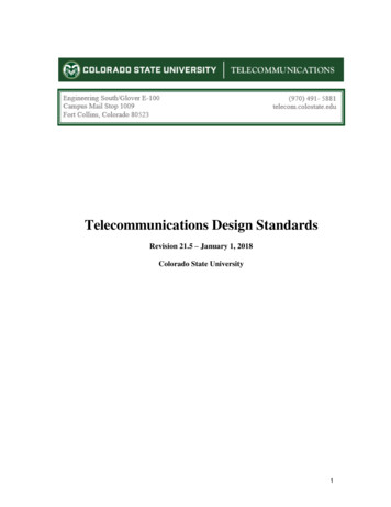
PQE204Facility and EquipmentGrounding to EnhanceEquipment Performance2011Course: PQ-GND204Presented by:PowerCET Corporation3350 Scott Blvd. Bldg. 55 Unit 1Santa Clara, CA 95054408/988-1346 Fax 408/988-4869E-mail: training@powercet.comURL: http://www.powercet.comGrounding Earthing (European convention)–Establishing a bond to earth at the facility service entrance for the electricaldistribution system. Grounding (U.S. convention)–Establishing fault clearing paths within a facility for the electrical distribution systemand for equipment within the facility. Referencing–Establishing a chassis contact to an external point to limit voltage rise.MagicGroundingVsScienceGrounding 2007-2011 by PowerCET Corporation, All rights reserved1
PQE204The Equipment Ground ConnectionyDC return referenced to chassisyChassis bonded to safety groundGrounding Concepts & References The effects of impedance &frequencyFaraday cage & Kirchoff's Voltageand Current LawsNational Electrical Code 2007-2011 by PowerCET Corporation, All rights reserved2
PQE204What Drives PQ Inspections? Ground resistance measurements required for newconstruction Equipment problems Nuisance GFI (ground fault interrupt) Communications problems Lighting problems Lightning problems “If it’s not power quality – then it must be grounding.”Common Grounding Issues There isn’t any grounding.There is too much “grounding”.The grounding is misapplied.There are some serious/stupid wiring problems.The equipment is really the problem– Power frequency leakage currents– EMI/RFI. 2007-2011 by PowerCET Corporation, All rights reserved3
PQE204Origins For Grounding Concepts Electrical code–Single point grounding–Fault path to electrical service Telecommunications grounding–Traditional DC grounding practices–Ground start & signaling RF grounding–Antenna grounding Isolated grounding–U.S. practice"Earthing" Systems Three or four letter designation First letter is supply earthing– T indicates one or more points directly earthed– I indicates the supply is not earthed or is earthed through a fault limiting impedance Second letter indicates installation earthing– T indicates that conductive metalwork is directly connected to earth– N indicates that conductive metalwork is directly connected to the earthed neutral. US convention is TN -- not TT or IT Third and fourth letter describes earthed conductor arrangement– S indicates separate neutral and earthed conductors– C indicates combined neutral and earth conductor TN-S: consumers earth terminal connected to the supply protective conductor TN-C: consumers neutral and protective functions (ground) in a single conductor TN-C-S: consumers supply neutral and protective functions (ground) are combined and earthed 2007-2011 by PowerCET Corporation, All rights reserved4
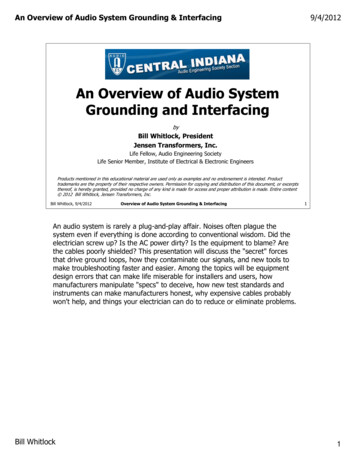
PQE204Earthing (Grounding) SystemsIT Earthing SystemUtility not earthed or earthed via impedanceFacility earthed independently of utilityTT Earthing SystemUtility directly earthedFacility earthed independently of utilityTN Earthing SystemUtility directly earthed (and frequently in US)Facility grounding bonded to earthed utilitySoil Conditions 2007-2011 by PowerCET Corporation, All rights reserved5
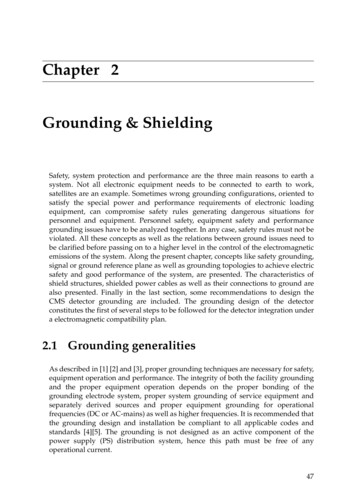
PQE204Soil Type vs Resistivity IEEE Std. 142-1991–Grounding of Industrial and Commercial Power SystemsSoil TypeAverage ResistivityOhms per CM5/8" x 10' Driven RodOhms ResistanceWell graded gravel, gravel-sand60,000 -- 100,000180 -- 300Loose gravel, gravel-sand100,000 -- 250,000300 -- 750Clayey gravel, sand-clay20,000 -- 40,00060 -- 120Silty sands, sand-silts mixtures10,000 -- 50,00030 -- 150Clayey sands, sand-clay mixtures5,000 -- 20,00015 -- 60Silty or clayey fine sands w/plasticity3,000 -- 8,0009 -- 24Fine sandy or silty soils, elastic silts8,000 -- 30,00024 -- 90Gravelly clays, sandy clays, silty clays,lean clays2,500 -- 6,000(moisture related)17 -- 18(moisture related)Inorganic clays, high plasticity1,000 -- 5500(moisture related)3 -- 16(moisture related)Soil Resistivity Vs Water Content 1 IEEE Std. 142-1991Moisture Content(by weight)ResistivityOhms/cmSandy 414,0001612,0001810,000209,000228,000247,000 2007-2011 by PowerCET Corporation, All rights reserved6
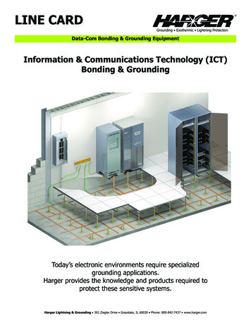
PQE204Effects of Moisture Content 8 Foot Rod Sandy LoamSoil Resistivity vs Temperature IEEE Std. 142-1991 (Green 08,00020687,00030866,000401045,000501224,000 2007-2011 by PowerCET Corporation, All rights reserved7
PQE204Effects of TemperatureSoil Resistivity vs Salt Content Soil type -- sandy loam - moisture content 15% by weight -temperature - 17 C Salts (copper sulfate, sodium carbonate etc.) must be EPA or localordinance approved for use AEMC -- Understanding Ground Resistance TestingAdded Salt% by weight of 045051901013020100 2007-2011 by PowerCET Corporation, All rights reserved8
PQE204Electrode Grounding Resistance NEC 25 Ohms or supplement NEC 250-56 [2005] NEC 250.53(A)(2) Exception [2011] Health Care IEEE Std. 602-1996 (White) Section (10.4.5.2) No more than 10 ohms 5 Ohms or less preferred Industrial Plants ANSI/IEEE Std. 141-1986 (RED) Section 7.5.2 1 ohm or less for substations 5 ohms or less for industrial plants Sphere of influence Radius equals length of buried rodGrounding Sphere of Influence Common Grounding Electrode NEC 250.58 [2011] Parallel ground rods considered a singlegrounding electrode Multiple services serving the same facilitymust use the same groundingelectrode(s). Radius length Combined resistance Rod length No less than 8 feet (2.5m) NEC 250.52(A)(5) [2011] 2007-2011 by PowerCET Corporation, All rights reserved9
PQE204Grounding Sphere of Influence (2) 6 foot minimum separation–NEC-250-53(A)(3) [2011] Local codes may specify ground rod separation IEEE Std. 142-1991 (Green Book)–Grounding of Industrial and Commercial Power Systems–Table 13 --provides resistance calculation methodsGrounding Protection? 2007-2011 by PowerCET Corporation, All rights reserved10
PQE204Chemical Treatments Soil treatment Specialized system Bentonite (kitty litter) Calsolite (salts) Open systems Local requirements EPA impactElectrolysis Electrochemical series Galvanic BatteryMagnesium (-2.34V)Aluminum (-1.67V)Iron (-0.44V)Tin (-0.14)Copper ( 0.34V)Stainless SteelGold ( 1.42V) 2007-2011 by PowerCET Corporation, All rights reserved11
PQE204Measuring Electrode ResistanceMade Electrode Earth Resistance NEC 250.53 Grounding Electrode System Installation NEC 250.53(A)(2) [2011]– A single rod, pipe or plate electrode shall be supplemented by anadditional electrode of a type specified in 250.52(A)(2) through (A)(8). NEC 250.53(A)(2) Exception [2011]– “If a single rod, pipe or plate grounding electrode has a resistance to earthof 25 ohms or less, the supplemental electrode shall not be required.” 2007-2011 by PowerCET Corporation, All rights reserved12
PQE204Grounding Measurements - 3 Pt.3 Pt. Measurement ComplicationsEarth Ground Resistance Testing for LowVoltage Power SystemsKenneth M. MichaelsIEEE Transactions - Industry ApplicationsJan/Feb 1995 2007-2011 by PowerCET Corporation, All rights reserved13
PQE2042 Pt. Clamp-on Measurements Designed for use with power poles Common neutral/groundconnections provides essentiallyan "infinite" ground connection Measurement reflect attachmentpoint versus all utility groundconnectionsClamp-On Complications Four separate measurement points Results vary from 2.8 Ohms to 1990 ohms Variable results caused by loop inductance/resonanceEarth Ground Resistance Testing for Low Voltage Power SystemsKenneth M. MichaelsIEEE Transactions - Industry Applications Jan/Feb 1995 2007-2011 by PowerCET Corporation, All rights reserved14
PQE204Four Point Resistivity Measurement Undisturbed native soil necessary Current injected between C1 and C2 with voltage measured fromP1 to P2.Earthing & Grounding General NEC 250 I [2011] System Grounding NEC 250 II [2011] Grounding Electrode System NEC 250 III [2011] 2007-2011 by PowerCET Corporation, All rights reserved15
PQE204The Roles of Grounding General requirements–NEC 250.4 [2011]–Establish voltage reference–Limit touch potential–Clear electrical faults–Carry lightning currents Performance issues–Provide equipment reference–Provide RF/ESD discharge pathGrounding Electrode System (GES) National Electrical Code Article 250–Electrical service entrance bonding–NEC 250-20 [2011]–Incoming utility neutral or internal facility neutral–Grounding electrode system ––NEC 250.50 [2011]–Structural steel where effectively grounded–"All grounding electrodes as described in 250.52(A)(1) through (A)(7) that are present at each building orstructure served shall be bonded together to form the grounding electrode system.“–Ufer grounds (concrete encased electrode)–Building footings if designed as Ufer grounds–Water pipes–Ground ring–Plate electrodes–Driven grounding rods 2007-2011 by PowerCET Corporation, All rights reserved16
PQE204Grounding Electrode System GES - NEC 250-50 [2011]–Water Pipe - NEC 250.52(A)(1)–Driven Ground - NEC 250.52(A)(5)–Structural Steel - NEC 250.52(A)(2)–Water Pipe must be supplemented–NEC 250.53(D)(2) [2011 Grounding electrode conductor mustbe continuous–NEC 250.64(C) [2011] Not allowed–Metal underground gas pipes–Aluminum electrodes–NEC 250.52(B) [2011]Bonds to Water Pipes Underground water pipecannot be the sole groundingmeans– NEC 250.53(D)(2) [2011]– Must be supplemented by amade electrode Bond within 5' of point ofentry– NEC 250.68(C)(1) [2011] Connection Quality? 2007-2011 by PowerCET Corporation, All rights reserved17
PQE204Water Meters & the GES Metering–Must not impede grounding path–NEC 250.68(B) [2011]Gas Pipes Underground gas pipes–“shall not be used as grounding electrodes”–NEC 250.52(B)(1) [2011] Gas pipes inside facility–Bonding after shutoff valve–“If installed in, or attached to, a building or structure, a metal piping system(s),including gas piping, that is likely to become energized shall be bonded to theservice equipment enclosure; the grounded conductor at the service; the groundingelectrode conductor, if of sufficient size; or to one or more of the groundingelectrodes used.”–NEC 250.104(B) [2011]–The problem lies with the term “likely.” 2007-2011 by PowerCET Corporation, All rights reserved18
PQE204Faults to CSST Multiple adjacent holes of similarsize– Frequently reported fromindirect lightning– Adjacent arcs unlikely to existconcurrently– Likely serial from multiplestroke lightning flash– Power system only sourcelikely to deliver similar energyin successive arcs– CSST Corrugated stainlesssteel tubingCSST Arc Damage Mechanisms Direct Lightning Strikes– Fraction of lightning currentflows onto CSST through arc Return stroke Continuing current– Sufficient current magnitudeand duration to causeobserved damage Indirect Lightning Strikes– Indirect lightning currents toosmall and too short duration todamage CSST– Indirect overvoltage ( 50 kV)causes multiple flashovers,including AC power system– AC power fault current flowsthrough arc– Sufficient current magnitudeand duration to cause observeddamage– Power fault currents also likelycause of many fires notinvolving gas pipes 2007-2011 by PowerCET Corporation, All rights reserved19
PQE204Solutions to Gas Pipe Damage Direct Strikes– Install at least minimallightning protection system– Bond all metal services tomain building and powersystem ground Including gas pipes onbuilding side of service– All gas pipes, not justCSST! Indirect Strikes– Ground ungrounded roofpenetrations Preferably throughlightning protection system– Bond all metal services to mainbuilding and power systemground Including gas pipes onbuilding side of service– Evaluate benefit of earthleakage relays on AC powersystemGrounding Connections 2005 NEC 250.8 [2005]– "Grounding conductor andbonding jumpers shall beconnected by exothermicwelding, listed pressureconnectors, listed clamps, orother listed means. Connectiondevices or fittings that dependsolely upon solder shall not beused. Sheet metal screws shallnot be used to connectgrounding conductors orconnections devices toenclosures." 2007-2011 by PowerCET Corporation, All rights reserved20
PQE204Grounding Connections 2011 Recognized attachment methods NEC 250.8(A) [2011] Exothermic Clamp Listed pressure connectors Machine type or thread formingscrews with at least two threads forcontact (sheet metal screws notincluded) Sole use of solder not allowed NEC 250.8(B) [2011]Grounding Conductor Bonding Bond grounding conductor toboth ends NEC 250.64(E) [2011] Connections must be clean andpermanent No sheet metal screws 2007-2011 by PowerCET Corporation, All rights reserved21
PQE204Protecting Against Corrosion Protection of clamps and fittings–NEC 250.10 [2011] Clean surfaces–NEC 250.12 [2011]–Remove paint, varnish etc. If not resistant - Protection from corrosion–NEC 250.62 [2011] Kopr-Shield Compound–Slurry of copper–Anti-corrosiveFacility Grounding &Structural Continuity 2007-2011 by PowerCET Corporation, All rights reserved22
PQE204Types of Grounding Electrodes Driven ground rodsyCopper clad steel Plate electrodeyTwo square feet minimum - 1/4 inch thick steel (6.35mm) - 21/2' depth Ring groundyGrounding conductor buried around building perimeter Chemical groundsyTraditional rod or ring with chemical treatmentySpecialized ground rod with integral chemical treatment Concrete encased electrode (Ufer ground & GRIF)yMetallic conductor embedded in structural concreteGround Ring Ground ring– NEC 250.52(A)(4) [2011]yBuried at least 2.5' (762mm)yAt least 20' longyNo smaller than No. 2 gauge Augmented ring– Driven rods– Surface radials– Bond to structural steelyAt cornersyAt regular intervals 2007-2011 by PowerCET Corporation, All rights reserved23
PQE204Concrete Encased Electrode Concrete encased electrode (Uferground)– NEC250.52(A)(3) [2011]– At least 20 feet (6.1m) of zinc galvanized conductoror steel reinforcing bar not less than 1/2 inch or 20feet of bare No. 4 copper conductor– Encased in at least 2 inches (50.8mm) of concrete– Reinforcing bar may be bonded together by the usualsteel tie wires– NEC Reinforcing bar currents– Exterior bars carry more current .Safety Vs Performance NEC 250.52(A)(3) [2011] Concrete-encased Electrode "An electrode encased by at least 50mm(2in)of concrete, located within and near thebottom of a concrete foundation or footingthat is in direct contact with theearth.reinforcing bars shall be permitted tobe bonded together by the usual steel tie wiresor other effective means.“ Construction practices often leave the steelreinforcing bars without grounding/bonding. NEC Commentary: “If multiple concreteencased electrodes are present at a building orstructure, it shall be permissible to bond onlyone into the grounding electrode system. NEC Informational note: Concrete installedwith insulation vapor barriers, films or similaritems separating the concrete from the earth isnot considered to be in “direct contact” withthe earth 2007-2011 by PowerCET Corporation, All rights reserved24
PQE204Reinforced Concrete ConstructionSteel Beam Construction 2007-2011 by PowerCET Corporation, All rights reserved25
PQE204Ungrounded REBarUngrounded Metalwork 2007-2011 by PowerCET Corporation, All rights reserved26
PQE204Electrically Conductive Concrete Conductive components– Carbonaceous particles & metallic compounds Uses––––––Deicing & snow melting of roadways & bridgesGround plane effects in data centers & barnsReducing electrolysis in grounding systemsReducing earth resistance in grounding systemsIncreasing surge current capabilitiesEnhanced screen room control (Tempest)San Earth Enhanced Concrete 2007-2011 by PowerCET Corporation, All rights reserved27
PQE204Metal Cladding & Framework NEC 250.104(C) [2011]–Bonding of piping systemsand exposed structural steel–Exposed metal buildingframework that is notintentional or inherentlygrounded and likely to beenergized must be groundedper NEC 250.64.Multiple Building Grounding 2005 NEC 250.32 [2005] Common ac service If no common grounding conductor extends between the buildings with multiple circuits then eachbuilding must have an established grounding electrode system with a separate neutral-to-groundbond in each building. If a common grounded and grounding conductor extends between the buildings, and multiple circuitsexist then a grounding terminal will be required in the connected buildings and no individual neutralto-ground bonds will be permitted in each additional building. If a single circuit extends to a second building and both grounded and grounding conductors extendto the second building then no ground terminal will be required and a neutral-to-ground bond cannotbe established at the second building. 2007-2011 by PowerCET Corporation, All rights reserved28
PQE204Multiple Building Grounding 1 NEC 250.32 [2005] Common ac service NEC 250.32(B)(1) (2011) Buildings or Structures supplied by a Feeder(s) or Branch Circuit(s). If a common grounded and grounding conductor extends between the buildings, and multiple circuitsexist then a grounding terminal will be required in the connected buildings and no individual neutral-toground bonds will be permitted in each additional building.An equipment grounding conductor, as described in 250.118, shall be run with the supply conductors andbe connected to the building or structure disconnecting means and to the grounding electrodes(s).”Substantial neutral-ground voltages can develop that may adversely affect equipment in thesecond building.Multiple Building Grounding 2 NEC 250.32 [2005] Common ac service– If no common grounding conductor extends between the buildings with multiple circuitsthen each building must have an established grounding electrode system with a separateneutral-to-ground bond in each building. NEC 250.32(B)(1) Exception [2011]– “For installations made in compliance with previous editions of this Code that permittedsuch connection, the grounded conductor run with the supply to the building or structureshall be permitted to serve as the ground-fault return path if all of the followingrequirements continue to be met.” 2007-2011 by PowerCET Corporation, All rights reserved29
PQE204Multiple Building Grounding 3 Regardless what grounding is implemented, data networks extending betweenthe buildings are at risk. Shielded data cables grounded at each end can end up carrying return and faultcurrents. Lightning can easily destroy linked equipment.Vref1Vref2Lightning Protection Systems 2007-2011 by PowerCET Corporation, All rights reserved30
PQE204Facility Grounding & Lightning Lightning treatment–Bond ground terminals to GESyNEC 250-106 [2011]–Air terminal conductors and groundterminals are not to be used in lieu ofintended GESyNEC 250.106 [2011]–NFPA 780-2011 provides calculationfor clearance from down conductors dueto high voltage & ionization.–Formerly, 250.106 FPN 2 in earlier Codespecified 6' (1.83m) clear air spacing toconductive metalwork or 3' (0.92m spacingthrough wood, concrete or brick)Effective Earth Terminals Low impedancepaths to earth–Current density and pathresistance determinevoltage rise–Low dc resistance does notguarantee effective currenthandling–Surface radials may bemost effective with sandysoil but well watered topsoil–Lightning groundingsystems bonded toelectrical service and tofacility structural steel 2007-2011 by PowerCET Corporation, All rights reserved31
PQE204Lightning Transient Characteristics Return-stroke current–Unidirectional impulse (30 kA, 10 x 100 µs)–Continuing currents (100 A, 10 mS) Non-connecting upward leaders–Bipolar impulse (100 A, 10 x 100 µs) Induced currents–Unipolar & bipolar (10 A, 2 x 50 µs) Self Inductance Vs Voltage Rise–30kA return stroke with 10 meter conductor length–Conductor inductance; 1uH per meter–Voltage rise; -V Ldi/dt 10E-06(30E03/10E-06) 30,000V–Single conductor discharge path does not work!!!Electrical Services 2007-2011 by PowerCET Corporation, All rights reserved32
PQE204Common Facility Power Systems Single phase 240/120 Three phase 480/277 & 208/120Common & Problematic Service Three phase delta voltages (240 delta) Single phase voltages (240/120) High leg delta (crazy leg, red leg etc.) 2007-2011 by PowerCET Corporation, All rights reserved33
PQE204Power/Grounding Variations Floated wye–Ground referenced voltagesvary with leakage currents Floated delta-delta–Ground referenced voltagesvary with leakage currents Corner grounded delta–One leg at earth potential,others at phase-to-phasepotentialFloated Delta-Delta Service Absence of solid ground reference allows ground referencedvoltage fluctuations–Load related fluctuations usually within voltage envelope of service–Utility related fluctuations reflect primary voltages–Lightning transients create severe dv/dt 2007-2011 by PowerCET Corporation, All rights reserved34
PQE204Impedance Grounded Source High-impedance grounded neutralsystems– NEC 250-36 [2011]– Typically resistive but may be resonantor inductive– 480 to 1000Vac three phase systemswith No line-to-neutral loads– Ground fault detection required– Impedance sized to prevent arcingfaults– Neutral-to-ground bond sized formaximum current per the groundingimpedance (ANSI/IEEE 142-1991Green Book)– Equipment bonding jumper (fromequipment grounding conductors to thegrounding impedance) shall be sizedper 250.66 or 250.36B.Wye-to-Wye Services Facility transformers Utility systemsHHHighLowVoltageVoltageNNGHELPME?DATA LINK 2007-2011 by PowerCET Corporation, All rights reserved35
PQE204Transferred Earth Potential Transferred Earth Potential (TEP)–IEEE Std 142-1991 (Green Book)ySections 1.6.4; 1.6.7; & 4.2.6–Wye-to-Wye & 240/120yPadmount applications prone to TEPHHHighLowVoltageVoltageNEquipmentNVGVTEP Case History 2007-2011 by PowerCET Corporation, All rights reserved36
PQE204TEP; Lightning Two Miles DistantDistribution Grounding FeedersTransformersSeparately derived sourcesBranch circuit wiring 2007-2011 by PowerCET Corporation, All rights reserved37
PQE204Feeder Grounding Permanent, Continuous, & Contiguous Ampacity sufficient for fault currents–Conductors–Raceway–ConduitGrounding Conductor Sizing Article 250-122 [2011]–Wire size (AWG) tied to overcurrent protection (A)–If circuit length requires larger conductors, then grounding conductorsize must also increase proportionally–In a parallel circuit each grounding conductor must be fully sized perthe overcurrent protection for that parallel circuit–Table 250-122 conductor sizingy15Ay20Ay60Ay100Ay1000A 14 cu or 12 al 12 cu or 10 al 10 cu or 8 al 8 cu or 6 al 2/0 cu or 4/0 al 2007-2011 by PowerCET Corporation, All rights reserved38
PQE204Parallel Feeders (1) NEC–NEC 310.10(H)(1) [2011]–Symmetrical–Prevent objectionable ground current–Use same material for conductors–Use same material forconduits/raceways–Maintain same lengths–Use proper conductor placement–1/0 and larger–Grounding conductor sizingyNEC 250-122 [2011]Parallel Feeders (2) 2007-2011 by PowerCET Corporation, All rights reserved39
PQE204Separately Derived Sources Neutral continuity is the keydeterminant. If the neutral isinterrupted or switched then thesource is probably separatelyderived. If separately derived then thesource must be bonded to thebuilding grounding electrodesystem (GES). Autotransformers (voltagechangers) are not separatelyderived.Separately Derived Sources NEC 250-30 [2011]–Major re-write in 2011–Transformers, UPS equipment, Motor generators Figure status–A Not Separate -- Neutral is continuous–B Separately derived -- Neutral not continuous Bonding–NEC 250.30(A)(4) [2011]–Water pipes or steel, but water pipes not preferredunless metal pipes are continuous and maintained–Bonding to water pipes in areas servedyNEC 250.104(A)(1) [2011] 2007-2011 by PowerCET Corporation, All rights reserved40
PQE204Fault Clearing Primary Fault Secondary FaultVfaultVfaultVrefCommon Grounding Electrode In facilities lacking structural steel or continuous, metal water piping, acommon grounding electrode may be used for separately derived equipment. NEC 250.30(A)(6)(a) [2011] Conductor sizing Minimum size per is 3/0 AWG copper or 250 kcmil aluminum. 2007-2011 by PowerCET Corporation, All rights reserved41
PQE204Continual Neutral Generator Setup Not separately derived 3 Pole ATS–Automatic transfer switch GES–Grounding electrode systemSwitched Neutral Generator Setup Separately derived 4 Pole ATS–Automatic transfer switch GES–Grounding electrode system 2007-2011 by PowerCET Corporation, All rights reserved42
PQE204Ground Fault DetectionGround Fault Circuit Interrupt Protection for personnel: NEC 210.8 [2011]SHUNTTRIPGFI SENSETEST 2007-2011 by PowerCET Corporation, All rights reserved43
PQE204Facility Ground Fault Protection Service entrance–Protection for switchgearyNEC 230-95 [2011]y 1000 amperey 150V L-G but not exceeding 600V Phase-to-phaseyMaximum response levels: 1200 amperes & 1 secondySlowest and highest response levels at service entrance Exceptions–Service entrances with multiple input breakers (six or less) with ampacities equal to or less than 800amperes.–Continuous industrial services where the interupption of power poses more hazard than relying uponnormal overcurrent interruption–Services with high impedance grounded neutral systems. Emergency services–Interrupt not required; NEC 700.26 [2011]–Ground fault detection required - NEC 700.6(D) [2011]Ground Fault Interrupt 1 Polyphase -- single CT GFI -- "zero sequence"SHUNTTRIPGFI SENSE 2007-2011 by PowerCET Corporation, All rights reserved44
PQE204Ground Fault Interrupt 2 Polyphase -- Multiple CT GFI -- "residual"SHUNTTRIPGFI SENSEGround Fault Interrupt 3 Neutral-to-ground bond detect - "source"SHUNTTRIPGFI SENSE 2007-2011 by PowerCET Corporation, All rights reserved45
PQE204GFI Problems Magnetic pickup from adjacent circuits Voltage and current harmonics vs CT response EMI/RFI sensitivity Trips settings too low for the application GFI on primary of N/G bond in wye-to-wye systems Neutral return current flow through N/G bond CT inmultiple grounding systemsEquipment Grounding 2007-2011 by PowerCET Corporation, All rights reserved46
PQE204Equipment Grounding 250 VI & VII [2011]–Effectively groundedyNEC 250.4(A)(3) [2011]–Continuous & Contiguous - Capacity to safely conduct fault current–Limit voltage to ground (touch potential) - Ensure rapid fault clearing NEC 250.4(A)(5) [2011] Effective Ground-Fault Current Path–"Electrical equipment and wiring and other electrically conductive material likely tobecome energized shall be installed in a manner that creates a permanent, lowimpedance circuit facilitating the operation of the overcurrent device or grounddetector for high-impedance grounded systems. It shall be capable of safelycarrying the maximum ground-fault current likely to imposed on it from any point onthe wiring system where a ground fault mayu occur to the electrical supply source.The earth shall not be considered as an effective ground-fault current path."Equipment Performance Issues Complications–Equipment reference–Leakage current–DC common & ac ground–Induced chassis potentials 2007-2011 by PowerCET Corporation, All rights reserved47
PQE204Grounding Discontinuity Neutral/Ground Voltage Leakage current Grounding discontinuity Chassis voltage Data loss Equipment resetConnection Quality Connections become loose withage Screw connections Too loose -- bad Too tight -- bad Proper torque -- rare Grounding wire essential 2007-2011 by PowerCET Corporation, All rights reserved48
PQE204Equipment Emissions High frequency emissions–Pulse width modulation–Power factor correction–Clock/logic circuits–I/O circuits–Intentional RF use FCC limits–Class A (commercial)–Class B (residential)–9kHz and highery450kHz is the lower measurement levely127dBuV 2.24VrmsHigh Frequency Leakage Current Kirchoff's Laws prevail–Pulse width modulation (PWM) Noise–Power factor correction (PFC) Noise Skin effect & inductance dominate Ground is a path, not the terminuss2I RSKINEFFECTSELF INDUCTANCE 2007-2011 by PowerCET Corporation, All rights reserved49
PQE204Flexible Wiring Systems Intended use Limited length, voltage and ampacity Usual use - lighting circuits Types FMC - Flexible metalic conduit FMT - Flexible metalic tubing Metal Clad (MC) Grounding NEC 250.118(5) [2011] 6 feet length (1.83m) Less than 20 amperesEquipment Leakage Current UL limits–3.5mA power frequencies–Formerly 0.5 mA to 5mA–Portable, cord connected devices Circuit Testers–2mA maximum–Read & follow instructions!–Disconnect loads before use Sources–Capacitive coupling–Wiring errors–I/O circuits 2007-2011 by PowerCET Corporation, All rights reserved50
PQE204Receptacle Orientation NEC No specified position IEEE White Book IEEE Std. 602-1996 Section 4.2.2 "Ground pin or neutral blade up" Reduces accidental contact with exposed livecontacts.Randomly Placed Raceway Wiring NEC 300.20 Induced currents in metal enclosures or metalraceways [2011]–"Where conductors carrying alternating current are installed in ferrous metalenclosures or ferrous metal raceways, they shall be arranged so as to avoid heating thesurrounding ferrous metal by induction. To accomplish this, all phase conductors and,where used, the grounded conductor and all equipment grounding conductors shall begrouped together.“ PQ Implications:Grouping the wires will reduce coupling to adjacent circuits! 2007-2011 by PowerCET Corporation, All rights reserved51
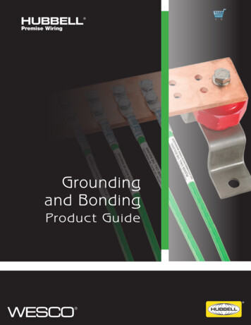
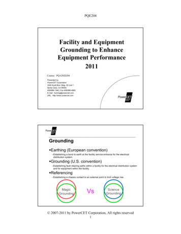
PQE204Conductor TypesCable 5 NEC/MCCable 1 NEC/MC3 phase, 3 grounds, no shield, aluminum interlockedCable 2 NEC/TC3 phase, 3 ground
–NEC 250.53(D)(2) [2011 Grounding electrode conductor must be continuous –NEC 250.64(C) [2011] Not allowed –Metal underground gas pipes –Aluminum electrodes –NEC 250.52(B) [2011] Bonds to Water Pipes Underground water pipe cannot be the sole grounding means – NEC 250.53(D)(2) [2011