Transcription
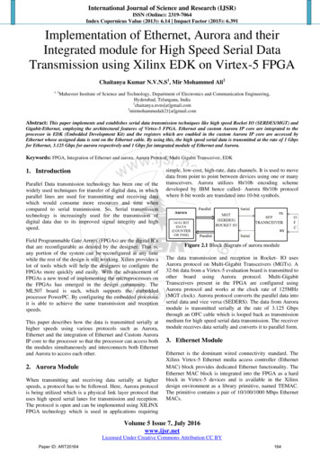
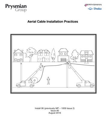
Application GuideShielded Cable for Ethernet ApplicationsIndustrial EnvironmentSelecting the proper infrastructure for network communications in an industrial environment is important. One commonly asked questionis ‘when and how to use shielded cabling’. Shielded cabling is often used in industrial environments to mitigate unwanted interferencethat finds its way into the Ethernet network cabling. Unshielded cable provides a degree of protection against interference due to thebalanced twisted pair design but does not provide the same level of protection as shielded cable. This ‘electrical balance’ allows thecable to minimize the effects of electro-magnetic interference (EMI), the better the balance the more protection from EMI. In industrialareas where interference is abundant the use of shielded cabling provides an added layer of protection.Theoretically, shielded cable is an ideal solution for managing interference of electrical noise, but this assumes proper design andinstallation of the physical infrastructure. Improper installation defeats the benefit of using shielded cable and can cause additionalproblems with other cabling infrastructure and electrical devices. Proper shielded cable installation in concert with appropriate systemdesign practices ensures unwanted interference does not affect network cabling infrastructure. Knowing these basic principles help toidentify potential problems and provide knowledge for system design.Types of Shielded CableM.I.C.E. TableIncreased Environmental SeverityMechanical Shock VibrationIngress Water DustClimatic 3E3Industrial
Shielded Cable ApplicationsThe primary application for shielded cable is environments that contains electrical noise sources near communication cabling. Theenvironment the cable is being installed will mostly determine whether to use shielded or unshielded cable. The ANSI/TIA-1005-Astandard details the MICE rating tic) system. MICE is an effective tool thatprovides helpful guidelines for quantifying the amounts of environmental stresses like electrical noise per classification. For moreinformation on MICE refer to the standard or the Panduit MICE guide material found on the Panduit website.Reasons to use shielded cable1. Mandated by company specification or local area requirement2. Data transmission is critical and infrastructure is located near plant floor environmenta. It is generally assumed that data transmission lines near the plant floor environment are exposedto some level of environmental stress3. Motion control and high-speed automation applicationsa. Many motion control vendors require or recommend shielded cable4. Known electrically noisy environment that does not require high flexibilitya. NOTE: Shielded cables are not as flexible as unshielded cables in high vibration installations;these cables can fail sooner than unshielded high flex cable5. MICE level of E2 or E3a. E2 and E3 MICE levels reflect severe levels of noise interferenceWhat is Electrical Noise?Electrical noise in the form of Electromagnetic interference (EMI) and Radio Frequency Interference (RFI) are common inindustrial environments. These forms of electrical noise can disturb the transmission of Ethernet network cabling. Sources ofelectromagnetic interference include; electric motors, variable frequency drives, contactors/relays, welding, fluorescent lighting,and radio communications. These devices are used in industrial environments and often located in the same space as Ethernetnetwork infrastructure. Electromagnetic interference can affect the network cabling through inductive, magnetic, or capacitivecoupling. Electrical noise can also be transmitted through common node grounds. However, you don’t have to understand all theseprinciples in deep detail to develop a well-designed physical infrastructure.Physical separation with air space and/or isolation barriers are effective but at certain points Ethernet network cabling is stillexposed to the noise hazard. Determining the source of the noise in a control system can be difficult and require significant amountof test equipment and time. Therefore, following best practices in the design of the physical infrastructure saves valuable time andresources while guaranteeing better performance.Grounding & Bonding SystemsGround and bonding systems are integral parts of Ethernet communication infrastructure, but it is not an absolute science.Each application has its own unique environmental noise and grounding situations that requires best practices and experienceto understand. Improper grounding and bonding can conduct noise that disrupts the transmission of the Ethernet packets. Thereare several standards to reference and a chart of common standards is provided in the additional resources section at the end ofthis document. One of the standards that focuses on industrial installations is ANSI/TIA-1005-A “Telecommunications InfrastructureStandard for Industrial Premises”. Compliance to this and other related standards aid in designing a trouble-free system with optimumperformance. There are two common types of grounding systems, equipotential/mesh & star grounding, which are commonlyreferenced in the standards.2
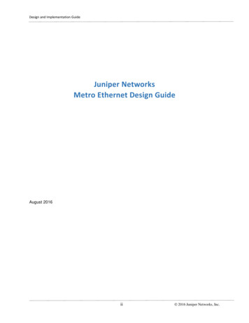
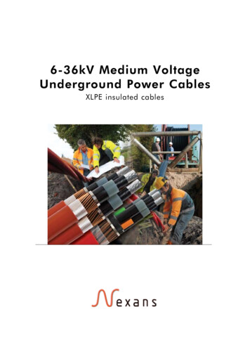
Equipotential/Mesh Grounding SystemEnclosure #2Enclosure #1The basis of this grounding system is to provide a low impedance path to ground (earth) between all the devices in the system.This method minimizes the electrical potential difference between the devices and therefore reduce the risk of ground loops. Thissystem requires the use of properly sized equalization conductors. The purpose of an equalization conductor is to provide a path between devices for noise currents to flow so that current does not flow on the shield of the shielded communication cable. Sizingof these conductors is illustrated in chart form in ANSI/TIA-1005-A. A matrix of bonding and equalization conductors, ‘meshgrounding’, will properly carry the currents so that it does not interfere with other devices. Refer to the diagram below for anillustration of this l.#6Encl.#4Encl.#7Encl.#5Encl.#8MotorConductor barCable clampCommunications cableConnection to tionsteelConnection to equipotential bonding system3
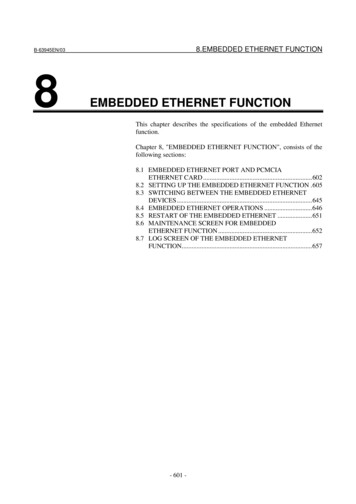
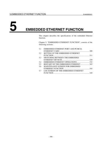
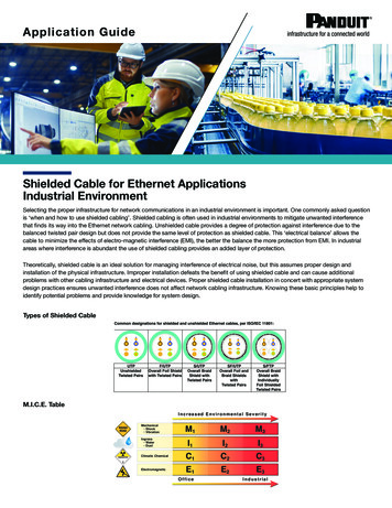
Star Grounding SystemThe basis of this system is to create a separate bonding system for communication commons. This setup can be utilized tomitigate ground loops in systems where equal grounding potential is not practical. Implementing this type of system will requireisolation of grounds and therefore the design may include different types of ground bars that are isolated from a back panel orenclosure. This type of grounding system allows the use of RC (resistor capacitor) device terminations. Star grounding imagebelow taken from ANSI/TIA-1005-A.RC Device TerminationThe use of an RC device termination (aka hybrid bonding or RC filter/ground/network) allows high frequency noise to pass throughthe loop and blocks the lower frequencies that may be present because of ground potential differences. To properly dissipate thenoise many of today’s industrial end devices (excluding network switches) include an RC device termination as shown below. RCdevice termination helps to open ground loops by providing a low impedance path at high frequencies and high impedance pathat low frequencies for the shield termination, this reduces ground noise currents.4Diagram from ANSI/TIA-1005-A showing device termination.
Proper Installation of Shielded CablePlanning the Ethernet cable infrastructure prior to installation provides opportunity to implement the best design possible. The designincludes: cable pathways, ducting, grounding, bonding, patch panels, cable types, and much more. Shielded Ethernet cable containsa conductive ‘shield’ layer around the overall cable and/or the individual twisted pairs (refer to additional resource section at the endof this document for more detail on types of shields). Use of shielded twisted pair Ethernet cables is an effective method to dissipateelectrical noise interference through the shield. The use of shielded connectors is recommended when using shielded cables. Thispractice allows the shield to be properly bonded from one end of the system to the other with ground connections only on theends of the entire link.There are two common problems that occur with shielded cabling in industrial applications. These problems are avoided with properinstallation. First, shielded cable that has the shield terminated in different locations having a potential difference can cause a ‘groundloop’ causing unwanted current to flow through the shield due to the potential difference. This is illustrated in the diagram below.Second, electrical noise (EMI or RF) can be coupled onto unprotected Ethernet communications cable and disrupt the transmissionsignal. The shield conductor in a shielded cable provides a return path for the disruption signal. The shield will protect the Ethernettransmission conductors from the interference by returning the interference signal to the source.5
Key ResourcesAdditional ResourcesStandards to ReferenceRegion of the WorldGeneric PremiseCabling StandardNorth andSouth AmericaEurope(Cenelec)Europe, OtherAreas of the WorldANSI / TIA-568 SeriesEN 50173-1IEC / ISO 11801 SeriesIndustrial PremisesCabling StandardANSI / TIA-1005-AEN 50173-3IEC / ISO 24702Grounding andBonding SystemsANSI / TIA-607-CEN 50174-2IEC / ISO 60364-5THE INFORMATION CONTAINED IN THIS APPLICATION GUIDE IS INTENDED AS A GUIDE FOR USE BY PERSONS HAVINGTECHNICAL SKILL AT THEIR OWN DISCRETION AND RISK. BEFORE USING ANY PANDUIT PRODUCT, THE BUYER MUSTDETERMINE THE SUITABILITY OF THE PRODUCT FOR HIS/HER INTENDED USE AND BUYER ASSUMES ALL RISK AND LIABILITYWHATSOEVER IN CONNECTION THEREWITH. PANDUIT DISCLAIMS ANY LIABILITY ARISING FROM ANY INFORMATIONCONTAINED HEREIN OR FOR ABSENCE OF THE SAME.www.panduit.com 2019 Panduit Corp.ALL RIGHTS RESERVEDCPAG18--SA-ENG5/2019
ANSI / TIA-607-C EN 50174-2: IEC / ISO 60364-5: Title: Shielded Cable for Ethernet Applications: Industrial Envrionment CPAG18--SA-ENG Subject: This article will review the different types of shielded cable and applications, along with different grounding and bonding systems such as equipotential/mesh grounding systems, star grounding systems and how to properly install shielded cable. Created .