Transcription
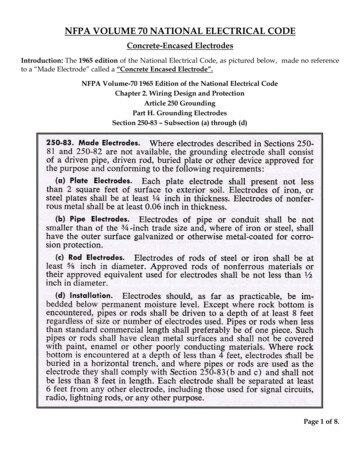
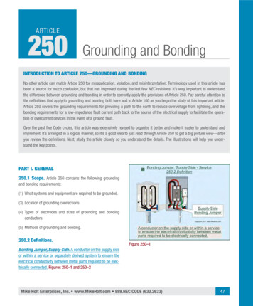
ARTICLE250Grounding and BondingINTRODUCTION TO ARTICLE 250—GROUNDING AND BONDINGNo other article can match Article 250 for misapplication, violation, and misinterpretation. Terminology used in this article hasbeen a source for much confusion, but that has improved during the last few NEC revisions. It’s very important to understandthe difference between grounding and bonding in order to correctly apply the provisions of Article 250. Pay careful attention tothe definitions that apply to grounding and bonding both here and in Article 100 as you begin the study of this important article.Article 250 covers the grounding requirements for providing a path to the earth to reduce overvoltage from lightning, and thebonding requirements for a low-impedance fault current path back to the source of the electrical supply to facilitate the operation of overcurrent devices in the event of a ground fault.Over the past five Code cycles, this article was extensively revised to organize it better and make it easier to understand andimplement. It’s arranged in a logical manner, so it’s a good idea to just read through Article 250 to get a big picture view—afteryou review the definitions. Next, study the article closely so you understand the details. The illustrations will help you understand the key points.PART I. GENERAL250.1 Scope. Article 250 contains the following groundingand bonding requirements:(1) What systems and equipment are required to be grounded.(3) Location of grounding connections.(4) Types of electrodes and sizes of grounding and bondingconductors.(5) Methods of grounding and bonding.250.2 Definitions.Figure 250–1Bonding Jumper, Supply-Side. A conductor on the supply sideor within a service or separately derived system to ensure theelectrical conductivity between metal parts required to be electrically connected. Figures 250–1 and 250–2Mike Holt Enterprises, Inc. www.MikeHolt.com 888.NEC.CODE (632.2633)47
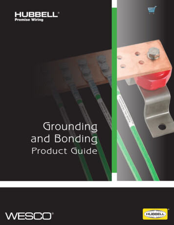
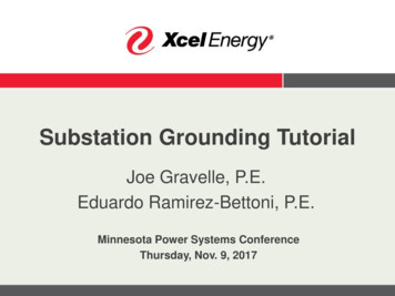
Grounding and Bonding250.2The current path shown between the supply source grounding electrode and the grounding electrode at the service mainshows that some current will flow through the earth but theearth is not part of the effective ground-fault current path.The effective ground-fault current path is intended to helpremove dangerous voltage from a ground fault by opening thecircuit overcurrent device. Figure 250–4Figure 250–2Effective Ground-Fault Current Path. An intentionally constructed low-impedance conductive path designed to carryfault current from the point of a ground fault on a wiring systemto the electrical supply source. Figure 250–3Figure 250–4Ground-Fault Current Path. An electrically conductive pathfrom a ground fault to the electrical supply source.Note: The ground-fault current path could be metal raceways,cable sheaths, electrical equipment, or other electrically conductive materials, such as metallic water or gas piping, steel-framing members, metal ducting, reinforcing steel, or the shields ofcommunications cables. Figure 250–5Figure 250–3Author’s Comment: In Figure 250–3, EGC representsthe equipment grounding conductor [259.118], MBJ represents the main bonding jumper, SNC represents theservice neutral conductor (grounded service conductor),GEC represents the grounding electrode conductor.48Author’s Comment: The difference between an “effective ground-fault current path” and a “ground-fault currentpath” is the effective ground-fault current path is “intentionally” constructed to provide a low-impedance faultcurrent path to the electrical supply source for the purposeof clearing a ground fault. A ground-fault current path is allof the available conductive paths over which fault currentflows on its return to the electrical supply source during aground fault.Mike Holt’s Illustrated Guide to Understanding 2011 NEC Requirements for Grounding vs. Bonding
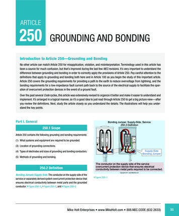
Grounding and Bonding250.4Author’s Comment: System grounding helps reduce firesin buildings as well as voltage stress on electrical insulation, thereby ensuring longer insulation life for motors,transformers, and other system components. Figure250–7Figure 250–5250.4 General Requirements for Grounding andBonding.Figure 250–7(A) Solidly Grounded Systems.(1) Electrical System Grounding. Electrical power systems,such as the secondary winding of a transformer are grounded(connected to the earth) to limit the voltage induced by lightning, line surges, or unintentional contact by higher-voltagelines. Figure 250–6Note: An important consideration for limiting imposed voltageis to remember that grounding electrode conductors shouldn’tbe any longer than necessary and unnecessary bends and loopsshould be avoided. Figure 250–8Figure 250–8Figure 250–6Mike Holt Enterprises, Inc. www.MikeHolt.com 888.NEC.CODE (632.2633)49
Grounding and Bonding250.4(2) Equipment Grounding. Metal parts of electrical equipmentare grounded (connected to the earth) to reduce induced voltage on metal parts from exterior lightning so as to prevent firesfrom an arc within the building/structure. Figure 250–9Author’s Comment: Grounding metal parts helps drainoff static electricity charges before flashover potential isreached. Static grounding is often used in areas where thedischarge (arcing) of the voltage buildup (static) can causedangerous or undesirable conditions [500.4 Note 3].DANGER: Because the contact resistance of an electrode to the earth is so high, very little fault currentreturns to the power supply if the earth is the onlyfault current return path. Result—the circuit overcurrent device won’t open and clear the ground fault, andall metal parts associated with the electrical installation,metal piping, and structural building steel will becomeand remain energized. Figure 250–11Figure 250–9DANGER: Failure to ground the metal parts can resultin high voltage on metal parts from an indirect lightningstrike to seek a path to the earth within the building—possibly resulting in a fire and/or electric shock. Figure250–10Figure 250–11(3) Equipment Bonding. Metal parts of electrical raceways,cables, enclosures, and equipment must be connected tothe supply source via the effective ground-fault current path.Figures 250–12 and 250–13Figure 250–1050Mike Holt’s Illustrated Guide to Understanding 2011 NEC Requirements for Grounding vs. Bonding
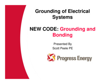
Grounding and BondingFigure 250–12250.4Figure 250–14 The time it takes for an overcurrent device to open isinversely proportional to the magnitude of the fault current. This means the higher the ground-fault currentvalue, the less time it will take for the overcurrent deviceto open and clear the fault. For example, a 20A circuitwith an overload of 40A (two times the 20A rating) takes25 to 150 seconds to open the overcurrent device. At100A (five times the 20A rating) the 20A breaker trips in5 to 20 seconds. Figure 250–15Figure 250–13Author’s Comments: To quickly remove dangerous touch voltage on metalparts from a ground fault, the fault current path musthave sufficiently low impedance to the source so thatfault current will quickly rise to a level that will open thebranch-circuit overcurrent device. Figure 250–14Figure 250–15Mike Holt Enterprises, Inc. www.MikeHolt.com 888.NEC.CODE (632.2633)51
Grounding and Bonding250.4(4) Bonding Conductive Materials. Electrically conductivematerials such as metal water piping systems, metal sprinkler piping, metal gas piping, and other metal-piping systems, as well as exposed structural steel members likely tobecome energized, must be connected to the supply sourcevia an equipment grounding conductor of a type recognized in250.118. Figure 250–16Figure 250–17Figure 250–16Author’s Comment: The phrase “likely to become energized” is subject to interpretation by the authority havingjurisdiction.(5) Effective Ground-Fault Current Path. Metal parts of electrical raceways, cables, enclosures, or equipment must be bondedtogether and to the supply system in a manner that creates alow-impedance path for ground-fault current that facilitates theoperation of the circuit overcurrent device. Figure 250–17Figure 250–18Because the earth isn’t suitable to serve as the required effective ground-fault current path, an equipment grounding conductor is required to be installed with all circuits. Figure 250–19Author’s Comment: To ensure a low-impedance groundfault current path, all circuit conductors must be groupedtogether in the same raceway, cable, or trench [300.3(B),300.5(I), and 300.20(A)]. Figure 250–1852Mike Holt’s Illustrated Guide to Understanding 2011 NEC Requirements for Grounding vs. Bonding
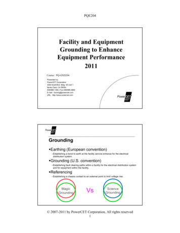
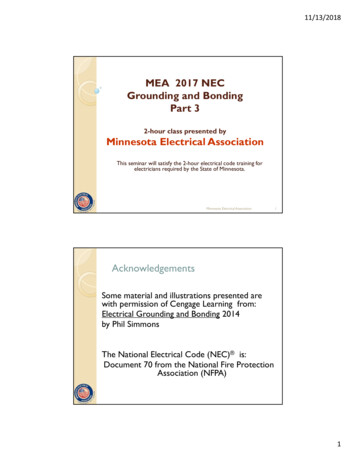
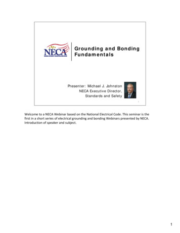
Grounding and Bonding250.4DANGER: Because the contact resistance of an electrodeto the earth is so high, very little fault current returns tothe power supply if the earth is the only fault currentreturn path. Result—the circuit overcurrent device won’topen and all metal parts associated with the electricalinstallation, metal piping, and structural building steelwill become and remain energized. Figure 250–21Figure 250–19Question: What’s the maximum fault current that can flowthrough the earth to the power supply from a 120V groundfault to metal parts of a light pole that’s grounded (connected to the earth) via a ground rod having a contactresistance to the earth of 25 ohms? Figure 250–20(a) 4.80A(b) 20AAnswer: (a) 4.80A(c) 40A(d) 100AFigure 250–21I E/RI 120V/25 ohmsI 4.80AEARTH SHELLSAccording to ANSI/IEEE 142, Recommended Practice forGrounding of Industrial and Commercial Power Systems(Green Book) [4.1.1], the resistance of the soil outwardfrom a ground rod is equal to the sum of the series resistances of the earth shells. The shell nearest the rod hasthe highest resistance and each successive shell hasprogressively larger areas and progressively lower resistances. Don’t be concerned if you don’t understand thisstatement; just review the table below. Figure 250–22Distance from RodSoil Contact Resistance1 ft (Shell 1)68% of total contact resistance3 ft (Shells 1 and 2)75% of total contact resistance5 ft (Shells 1, 2, and 3)86% of total contact resistanceFigure 250–20Mike Holt Enterprises, Inc. www.MikeHolt.com 888.NEC.CODE (632.2633)53
Grounding and Bonding250.4Figure 250–22Figure 250–23Since voltage is directly proportional to resistance, thevoltage gradient of the earth around an energized groundrod will be as follows, assuming a 120V ground fault:Soil ContactResistanceVoltageGradient1 ft (Shell 1)68%82V3 ft (Shells 1 and 2)75%90V5 ft (Shells 1, 2, and 3)86%103VDistance from Rod(B) Ungrounded Systems.Author’s Comment: Ungrounded systems are those systems with no connection to the ground or to a conductivebody that extends the ground connection [Article 100].Figure 250–23(1) Equipment Grounding. Metal parts of electrical equipmentare grounded (connected to the earth) to reduce induced voltage on metal parts from exterior lightning so as to prevent firesfrom an arc within the building/structure. Figure 250–24Author’s Comment: Grounding metal parts helps drainoff static electricity charges before an electric arc takesplace (flashover potential). Static grounding is often usedin areas where the discharge (arcing) of the voltagebuildup (static) can cause dangerous or undesirable conditions [500.4 Note 3].54Figure 250–24CAUTION: Connecting metal parts to the earth (grounding) serves no purpose in electrical shock protection.(2) Equipment Bonding. Metal parts of electrical raceways,cables, enclosures, or equipment must be bonded together ina manner that creates a low-impedance path for ground-faultcurrent to facilitate the operation of the circuit overcurrentdevice.Mike Holt’s Illustrated Guide to Understanding 2011 NEC Requirements for Grounding vs. Bonding
Grounding and Bonding250.6The fault current path must be capable of safely carrying themaximum ground-fault current likely to be imposed on it fromany point on the wiring system where a ground fault may occurto the electrical supply source.(3) Bonding Conductive Materials. Conductive materials suchas metal water piping systems, metal sprinkler piping, metalgas piping, and other metal-piping systems, as well as exposedstructural steel members likely to become energized must bebonded together in a manner that creates a low-impedancefault current path that’s capable of carrying the maximum faultcurrent likely to be imposed on it. Figure 250–25Figure 250–26Author’s Comment: A single ground fault can’t becleared on an ungrounded system because there’s no lowimpedance fault current path to the power source. The firstground fault simply grounds the previously ungroundedsystem. However, a second ground fault on a differentphase results in a line-to-line short circuit between the twoground faults. The conductive path, between the groundfaults, provides the low-impedance fault current path necessary so the overcurrent device will open.250.6 Objectionable Current.Figure 250–25Author’s Comment: The phrase “likely to become energized” is subject to interpretation by the authority havingjurisdiction.(4) Fault Current Path. Electrical equipment, wiring, andother electrically conductive material likely to become energized must be installed in a manner that creates a low-impedance fault current path to facilitate the operation of overcurrentdevices should a second ground fault from a different phaseoccur. Figure 250–26(A) Preventing Objectionable Current. To prevent a fire, electric shock, or improper operation of circuit overcurrent devicesor electronic equipment, electrical systems and equipmentmust be installed in a manner that prevents objectionable neutral current from flowing on metal parts.(C) Temporary Currents Not Classified as ObjectionableCurrents. Temporary currents from abnormal conditions, suchas ground faults, aren’t to be classified as objectionable current. Figure 250–27(D) Limitations to Permissible Alterations. Currents thatintroduce noise or data errors in electronic equipment are notconsidered objectionable currents for the purposes of this section. Circuits that supply electronic equipment must be connected to an equipment grounding conductor.Mike Holt Enterprises, Inc. www.MikeHolt.com 888.NEC.CODE (632.2633)55
Mike Holt’s Illustrated Guide to Understanding 2011 NEC Requirements for Grounding vs. Bonding: 250.2: Grounding and Bonding: The current path shown between the supply source ground-ing electrode and the grounding electrode at the service main sh