Transcription
11/13/2018MEA 2017 NECGrounding and BondingPart 32-hour class presented byMinnesota Electrical AssociationThis seminar will satisfy the 2-hour electrical code training forelectricians required by the State of Minnesota.Minnesota Electrical Association1AcknowledgementsSome material and illustrations presented arewith permission of Cengage Learning from:Electrical Grounding and Bonding 2014by Phil SimmonsThe National Electrical Code (NEC) is:Document 70 from the National Fire ProtectionAssociation (NFPA)1
11/13/2018Objectives: The requirements for the grounding electrodesystemGrounding electrodes required and those notpermitted to be usedInstallation requirements for the groundingelectrode systemRequirements for supplementary groundingelectrodesInstallation of auxiliary grounding electrodes3Objectives: Resistance requirements for rod, pipe and plateelectrodesRequirements for the use of a common groundingelectrodeInstallation requirements for grounding electrodeconductorsMinimum size of grounding electrode conductorsMethods for connecting grounding and bondingconductors to grounding electrodesUsing building structural metal members and water pipesas grounding electrode conductors42
11/13/2018250.50 Grounding Electrode System All grounding electrodes described in250.52(A)(1) through (A)(7) that are present ateach building or structure served are required tobe bonded together to form the groundingelectrode system. If none of these grounding electrodes exist, oneor more of the grounding electrodes in250.52(A)(4) through (8) must be installed andused.5250.50 Grounding Electrode SystemException: Concrete-encased electrodes of existingbuildings or structures are not required to be part of thegrounding electrode system if the steel reinforcing barsor rods are not accessible for use without disturbing theconcrete. Do not expose re-bar to soil conditions63
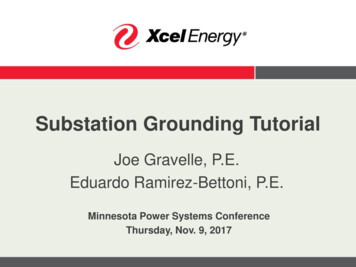
11/13/2018250.50 Grounding Electrode SystemCopyright Cengage Learning7250.52(A) Electrodes Permitted ForGroundingUse of the grounding electrodes in this sectionbecomes mandatory due to the requirement in250.50 Some electrodes are traditionally installed by othertrades Electrodes in (A)(4) through (A)(8) are ofteninstalled by electricians Some installation requirements are contained in thedescription of the grounding electrodes 84
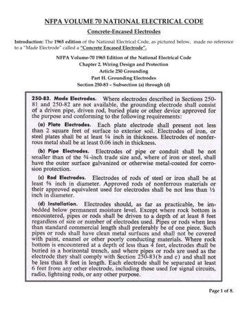
11/13/2018250.52(A)(1) Metal UndergroundWater PipeRequired to be usedif 10 ft. or more isin direct contactwith the earth9Copyright Cengage LearningGround clamp to water pipe105
11/13/2018New 250.52(A)(2) Metal in ground supportstructures One or more metal in-ground supportstructures in direct contact with the earth for10 ft. or more vertically, with or withoutconcrete encasement. If more than one support structure is present,then permitted to bond to only one in thegrounding electrode system250.52(A)(2) Frame of the Building orStructure Methods of making an earth connection of themetal frame of the building or structure aredescribed Requires direct contact with the earth, concreteencasement or by connection to concreteencased grounding electrode Once a recognized grounding electrode, it canbe used to bond other electrodes126
11/13/2018250.52(A)(2) Metal Frame of theBuilding or StructureCopyright Cengage Learning13Hold down bolts for bldg. steel147
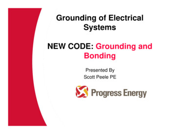
11/13/2018250.52(A)(3) Concrete EncasedElectrode Requiredto be usedwhere present at thebuilding or structureserved Useof theseelectrodes pioneeredin the early 1940s forthe US Army in aridclimates (Ufer)Copyright Cengage Learning15Re-bar clamp168
11/13/2018250.52(A)(4) Ground Ring To encircle thebuilding or structureBe in direct contactwith the earthConsist of at least 20ft of bare copperconductor notsmaller than #2 AWGBurial depth is notless than 2½ ft[250.53(F)]17Copyright Cengage Learning250.52(A)(5) Rod and Pipe Electrodes Ideally, installed belowpermanent moisturelevel At least 8 ft in length Specifications mayrequire thicker orlonger electrodes andinstallation in specificconfigurationsCopyright Cengage Learningmore189
11/13/2018Copyright Cengage Learning19Other Listed electrodesBy Superior Grounding Systems2010
11/13/2018250.52(A)(7) Plate Electrodes Each plate electroderequired to expose notless than 2 sq ft toexterior soil Some interpret rule aspermitting a 12 in.square plate (verify) 2sided ? Installation rules are at250.53(A), (B), (E), (H)Copyright Cengage Learning21Buried ground plate electrode11
11/13/2018250.52(A)(8) Other GroundingElectrodesIncluded in “if none of the electrodes in 1-4, thenone of the 4-8 electrodes must be installed” - arelocal metal underground systems or structures suchas: Piping systems Underground tanks Underground metal well casings that are noteffectively bonded to a metal water pipe23250.52(B) Electrodes Not Permitted forGrounding1. Metal underground gaspiping systems [Interior piping systemsare required to bebonded by 250.104(B)]2. Aluminum structures3. (NEW) The structuralreinforcing steel under apool2412
11/13/2018250.53 Grounding Electrode SystemInstallation Rod, pipe and plate grounding electrodes arerequired to meet the requirements of (A)(1)through (A)(3) Following See 547.9 and 547.10 for special grounding andbonding requirements for agricultural buildings25250.53(A)(1) Rod, Pipe, and PlateElectrodes Where practicable,these electrodesare to beembedded belowpermanentmoisture level Must be free fromnonconductivecoatings26Copyright Cengage Learning13
11/13/2018Exposed or Buried250.53(A)(2) Supplemental ElectrodeRequiredWhere only a Single rod, pipe, or plate electrode is usedit shall be supplemented by an additional electrode of atype specified in 250.52(A)(2) through (A)(8).The supplemental electrode shall be permitted to bebonded to one of the following:1. Rod, pipe, or plate electrode2. Grounding electrode conductor3. Grounded service-entrance conductor4. Nonflexible grounded service raceway5. Any grounded service enclosure2814
11/13/2018Exception to 250.53(A)(2)If resistance of single rod, pipe or plate is 25 ohmsor less, a supplemental grounding electrode is notrequired29250.53(A)(2) Resistance of Rod, Pipe andPlate ElectrodesCopyright Cengage Learning3015
11/13/2018Earth Resistance Tester Testwith properequipment notcommon voltmeter, ohmmeteror ammeter Followmanufacturer’sinstructionsCopyright Cengage Learning31Three point test for fall of potential3216
11/13/2018250.53(A)(3) Multiple Rods, Pipes orPlates If supplemental rod,pipe or plateelectrodes arerequired, then spacenot less than 6 ft apart Avoid overlapping“sphere of influence” Installation ofadditional electrodesnot required to obtain25 ohms resistance33IN – Note, Spacing of Rods The paralleling efficiency of ground rods isincreased by spacing them twice the length of thelongest rod. This spacing may be required in manufacturer’sinstallation requirements and is so stated, mustbe followed to comply with 110.3(B).3417
11/13/2018Table 3-2 Current Through RodsSystem Voltage Rod .84,00035250.53(B) Electrode SpacingIf more than one ofthe rod, pipe, orplate, electrodes areused, (A5–A7), spaceelectrodes of onegrounding systemnot less than 6 ft.from the othersystem (striketerminations)Copyright Cengage Learning3618
11/13/2018250.53(C) Bonding Jumper Bonding jumper isused to connectgroundingelectrodes together Install per 250.64(A),(B) and (E) Size per 250.66 Connect per 250.7037Table 3-1 (Based on 2-500 kcmil SEC)GroundingElectrodeMinimum SizeBonding JumperNEC Section orTableWater pipe tobuilding steel2/0 AWG CopperTable 250.66Building steel toconcrete encased2 AWG copper*Concreteencased toground ring2 AWG copper**250.66(C)Ground ring torod or plate6 AWG copper250.66(A)250.66(B) and (C)* Would be 4 AWG if concrete-encased electrode were connectedafter the ground ring**Same size as for ground ring, up to 3/0 per 250.66(C))19
11/13/2018250.53(D)(1) Continuity Continuity of the grounding path or the bondingconnection to interior piping shall not rely onwater meters or filtering devices and similarequipment. Use jumper Bond around any such equipment to assurecontinuity.39Copyright Cengage Learning4020
11/13/2018250.53(D)(2) Supplemental ElectrodeRequired Metal underground water pipe is required to besupplemented by another electrode specified in250.52(A)(2) through (A)(8). If a rod, pipe or plate is used, must comply withthe 25-ohm rule of 250.53(A)(2) Bond to grounding electrode conductor,grounded service conductor, nonflexible serviceraceway or grounded service enclosure41Copyright Cengage Learning4221
11/13/2018250.53(D)(2) Exception The supplemental grounding electrode is permitted tobe connected at any convenient point as covered in250.68(C)(1) Exception Industrial occupancy- interior metal water pipe can beused throughout if visible and no intervening nonconductive sections43250.53(F) Ground RingMust be buriednot less than30” below theearth’s surface4422
11/13/2018250.53(G) Rod and Pipe Electrodes Atleast 8 ft in contactwith the soil Ifrock bottom isencountered, install atmaximum 45 angle Ifrock bottom is thenencountered, burial intrench 2½ ft deep ispermitted45Rod and Pipe Clamps Listed clampsrequiredMust be suitable forthe conductor andthe rod or pipeListed for direct soilburial or concreteencasementMarked “DB”, alsosuitable for concreteencasement4623
11/13/2018250.53(H) Plate ElectrodeTo be installed not less then 30 in. below thesurface of the earth250.54 Auxiliary Grounding Electrodes Permitted to connectto equipmentgrounding conductor Not required tocomply with 250.50,250.53(C) or theresistancerequirements of250.53(A)(2)Exception Not permitted as effectiveground-fault current return path4824
11/13/2018Effect of Soil Moisture on Ground RodsThe resistivity ofthe soil variessignificantly basedon the moisturecontent49Effect of Soil Moisture on Ground RodsThe resistivity ofthe soil variessignificantly basedon the temperature5025
11/13/2018250.58 Common Grounding Electrode The same grounding electrode (system) is requiredto be used to ground the electrical system as wellas any equipment Where separate services, feeders or branch circuitssupply a building or structure, the same groundingelectrode must be used Two or more grounding electrodes that arebonded together are considered a single groundingelectrode51Copyright Cengage Learning5226
11/13/2018250.60 Use of Strike (Lightning)TerminationDevices Earth electrodes for striketermination devices notpermitted to be used inlieu if grounding electrodesystem for electrical supply Rule does not prohibitbonding groundingelectrodes together.See 250.106. Shall be bonded togetherCopyright Cengage Learning53250.62 Grounding Electrode Material Grounding electrode material shall be of copper,aluminum or copper clad aluminum. Conductors may be solid or stranded, an can beinsulated covered or bare.27
11/13/2018250.64(A) Aluminum or Copper-CladAluminum Conductors Bare Al. conductors not permitted in contactwith masonry or the earth or where subject tocorrosive conditions Where used outside, not permitted to beterminated within 18 in. of the earth55250.64(B) Securing and Protection AgainstPhysical Damage If exposed, grounding electrode conductor orenclosure must be securely fastened Permitted to be installed on or through framingmembers #6 AWG or larger that is free from exposure tophysical damage is permitted to be run alongsurface of building if securely fastened. If exposed to physical damage, protect withraceway5628
11/13/2018250.64(B) Securing and Protection AgainstPhysical Damage3. Grounding electrode conductors smallerthan 6 AWG must be protected by: Rigid metal conduitIntermediate metal conduitRigid nonmetallic conduitCable armor57250.64(B) Securing and ProtectionAgainst Physical Damage4. In contact with the earth are not required tobe buried as per 300.5 (burial depths) but shallbe buried to protect from physical damage.29
11/13/2018250.64(C)(1) ContinuousGrounding electrodeconductors to be in onecontinuous length unlessspliced by irreversiblecompression connectorslisted as grounding andbonding equipment orthe exothermic weldingprocess59250.64(C)(2) Continuous2. Sections of busbars are permitted to be connectedtogether to form a grounding electrode conductor6030
11/13/2018250.64(C)(3) Continuous3. Bolted, riveted, orweldedconnections ofstructural metalframes of buildingsare permitted61250.64(C) Continuous4. Threaded, welded,brazed, soldered, orbolted-flangeconnections of waterpiping are permitted6231
11/13/2018250.64(D) Building or Structure with MultipleDisconnecting Means in Separate EnclosuresPermitted where the service consists of more thana single enclosureThree methods permitted as following (D)(1) Grounding Electrode Conductor Taps (D)(2) Individual Grounding ElectrodeConductors (D)(3) Connections at a Common Location63250.64(D)(1) Grounding Electrode Conductor taps A common grounding electrode conductor is run from thegrounding electrode or grounding electrode system to thevicinity of the service equipment (no specific proximityspecified in rule) Common grounding electrode conductor shall be sized inaccordance with 250.66, based on the sum of the circular milarea of the largest ungrounded conductor(s) of each set ofconductors that supplies the disconnecting means. If service-entrance conductors connect directly to overheadservice conductors, service drop, underground serviceconductors, or service lateral, common grounding electrodeconductor shall be sized based on Table 250.66, note 1.6432
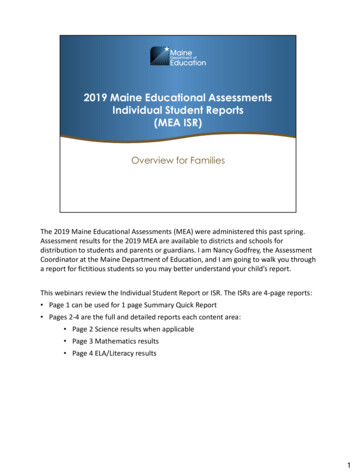
11/13/2018Common grounding electrode per 250.66Copyright Cengage Learning65Sizing Grounding Electrode ngElectrodeConductor200 A3/0 AWG167,800 cm4 AWG Tap400 A500 kcmil500,000 cm1/0 AWGTapTotal Area 667,800 cm2/0 AWGCommonServiceDisconnect6633
11/13/2018250.64(D)(1) Grounding Electrode Conductor taps Next figure shows overhead service with 3 servicedisconnecting means enclosures (6 permitted)Common grounding electrode conductor is run fromgrounding electrode to vicinity of service equipment (nospecific proximity specified in rule)Common grounding electrode conductor is sized fromTable 250.66 based upon the circular mil area ofungrounded service-entrance conductorsTap grounding electrode conductors are sized from Table250.66 based upon size of ungrounded service-entranceconductor to individual enclosures67Copyright Cengage Learning6834
11/13/2018Copyright Cengage Learning69250.64(F)(3) Installation to electrode Copper or aluminum busbar not smaller than ¼thick 2 in. wide and of sufficient length toaccommodate the number of terminationsnecessary for the installation is permitted formaking connections of common groundingelectrode conductor and grounding electrodeconductor taps. If aluminum busbar is used, comply with 250.64(A)7035
11/13/2018250.64(D)(1) Grounding ElectrodeConductor taps Next figure represents an overhead service with 6service disconnecting means enclosuresCommon grounding electrode conductor is run fromgrounding electrode to vicinity of service equipment (nospecific proximity specified in rule)Common grounding electrode conductor is sized fromTable 250.66 based upon the circular mil area ofungrounded service-entrance conductorsTap grounding electrode conductors are sized from Table250.66 based upon size of ungrounded service-entranceconductor to individual enclosures71Common conductor sizeTap sizeCopyright Cengage Learning7236
11/13/2018250.64(D)(1) - (3) Connection of Tap Conductors Tap conductors arerequired to beconnected to thecommon groundingelectrode withconnectors listed forbonding and grounding Common GroundingElectrode Conductorremains without a spliceor joint73Copyright Cengage Learning250.64(D)(2) Individual Grounding ElectrodeConductors Next figure represents service with 2 servicedisconnecting means enclosures (6 permitted)A GEC shall be connected between groundingelectrode system & one or more of following: (1) GC in each service equipment disconnecting meansenclosure (2) EGC installed with the Feeder (3) Supply-side bonding jumper Each GEC shall be sized in accordance with 250.66based on the service-entrance or feeder conductor(s)supplying the individual disconnecting means.7437
11/13/2018Copyright Cengage LearningGrounding electrode75250.64(D)(3) Common Location Next figure represents a service with 2 servicedisconnecting means enclosures (6 permitted)A GEC shall be connected in a wireway or otheraccessible enclosure on supply side of disconnectingmeans to one or more of following: (1) Grounded service conductor(s) (2) EGC installed with the feeder (3) Supply-side bonding jumper GEC sized from Table 250.66 based upon circular milarea of the ungrounded service-entrance conductors atpoint of connection7638
11/13/2018Supply side of service disconnect 250.66 based oncommon service conductor sizeCopyright Cengage Learning77250.64(E) Raceways and Enclosures forGrounding Electrode Conductors. Ferrous metal Raceways & enclosures for groundingelectrode conductors are required to be electricallycontinuous from point of connection to cabinets orequipment to the grounding electrode and must besecurely fastened to the ground clamp or fitting Ferrous metal raceways and enclosures shall bebonded at each end of the raceway or enclosure tothe grounding electrode or grounding electrodeconductor to create a parallel path Nonferrous metal raceways and enclosures shall notbe required to be electrically continuous.7839
11/13/2018250.64(E)BondingRequirementsBonding requirementsapply to both ends andto all intervening ferrousraceways, boxes andenclosures between theservice and groundingelectrode for enclosing aGEC79Copyright Cengage Learning250.64(E) Raceways and Enclosures forGrounding Electrode Conductors.(2) Methods. Bonding shall be in compliance with250.92(B) and ensured by one of the methods in250.92(B)(2) through (B)(4). (bonding a service) (3) Size. The bonding jumper for a groundingelectrode conductor raceway or cable armor shallbe the same size as, or larger than, the enclosedgrounding electrode conductor. (4) Wiring Methods. If a raceway is used asprotection for a grounding electrode conductor, theinstallation shall comply with the requirements ofthe appropriate raceway article. 8040
11/13/2018250.64(F) Installation to Electrode(s) Grounding electrode conductors, and bondingjumpers interconnecting grounding electrodes,are required to be installed as provided in (F)(1),(F)(2), or (F)(3). The grounding electrode conductor must besized for the largest grounding electrodeconductor required among all the electrodesconnected to it.81250.64(F)(1) Installation to Electrode(s)The grounding electrode conductor is permitted tobe run to any convenient grounding electrodeavailable in the grounding electrode system if theother electrodes, if any, are connected by bondingjumpers in accordance with the rules in 250.53(C).See 250.50 and Figure 3-1 and 250.53(C) and Figure3-158241
11/13/2018250.64(F)(2) Installation to Electrode(s) Grounding electrode conductors are permittedto be run to one or more grounding electrodesindividually. Size the individual grounding electrodeconductor from Table 250.66 and written articlebased on the type grounding electrode beingconnected.83GEC based on type of electrode84Copyright Cengage Learning42
11/13/2018250.64(F)(3)Bonding jumpers from grounding electrodes andgrounding electrode conductors are permitted tobe connected to an aluminum or copper busbar. The busbar must be securely fastened and beinstalled in an accessible location. Connections are required to be made by a listedconnector or by the exothermic welding process. If aluminum busbars are used, the installation isrequired to comply with 250.64(A) 85Copyright Cengage Learning8643
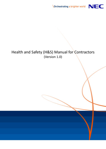
11/13/2018250.66 Size of AC Grounding ElectrodeConductor Size of Grounding Electrode Conductor for aservice, at building disconnecting means and forseparately derived systems not smaller than Table250.66 The table is modified for the specific groundingelectrodes by 250.66(A), (B) and (C)87Table 250.66 Grounding Electrode Conductor forAlternating-Current SystemsSize of the LargestUngrounded Service-EntranceConductor or Equivalent Areafor Parallel Conductors(AWG/kcmil)CopperAluminum orCopper-CladAluminumSize of Grounding ElectrodeConductor (AWG/kcmil)CopperAluminum orCopper-CladAluminum2 or smaller1/0 or smaller861 or 1/02/0 or 3/0642/0 or 3/04/0 or 25042Over 3/0through 350Over 250through 50021/0Over 350through 600Over 500through 9001/03/0Over 600through 1100Over 900through 17502/04/0Over 1100Over 17503/02508844
11/13/2018Notes to Table 250.66 abIf multiple sets of service-entrance conductors connectdirectly to a service drop, set of overhead serviceconductors, set of underground service conductors, orservice lateral, the equivalent size of the largest serviceentrance conductor shall be determined by the largestsum of the areas of the corresponding conductors ofeach set.Where there are no service-entrance conductors, thegrounding electrode conductor size shall be determinedby the equivalent size of the largest service-entranceconductor required for the load to be served.This table also applies to the derived conductors ofseparately derived ac systemsSee installation restrictions in 250.64(A)89250.66(A) Connections to Rod, Pipe, orPlate ElectrodesThat portion of thegrounding electrodeconductor that connectsdirectly to a single ormultiple rod, pipe, or plateelectrode and does notextend to otherelectrodes that wouldrequire larger conductors,the grounding conductorneed not be larger that #6 AWG90Copyright Cengage Learning45
11/13/2018250.66(B) Connections to ConcreteEncased ElectrodesThat portion of thegrounding electrodeconductor thatconnects directly tosingle or multipleconcrete encasedelectrode and doesnot extend to othertypes of electrodesthat would requirelarger conductors isnot required to belarger than # 4 AWG91Copyright Cengage Learning250.66(C) Connections to GroundRingsThat portion of thegrounding electrodeconductor thatconnects directly tothe ground ringelectrode, and doesnot extend to otherelectrodes thatwould require alarger conductor, isnot required to belarger than theground ringconductor92Copyright Cengage Learning46
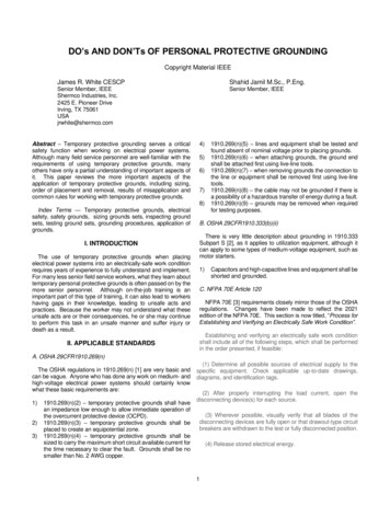
11/13/2018Table 3-5 Size GEC for Ground 2 or smaller2 or largerGroundingElectrodeConductor8 AWG2/0 or 3/02 or larger4 AWG 350 to 60022 AWG 350 to 6004/01/0 AWGOver 110022 AWGOver 11004/03/0 AWGAs specified by designer250.66 copper but notbut not required tolarger than Ringlarger than #2 AWG93250.68 Grounding Electrode ConductorConnectionsThe connection of a grounding electrode conductorat the service, at each building or structure wheresupplied by a feeder(s) or branch circuit(s), or at aseparately derived system and associated bondingjumper(s) shall be made as specified 250.68(A)-(C).9447
11/13/2018250.68(A) Accessibility All mechanical devices (elements) used to terminate theconnection of a grounding electrode conductor orbonding jumper to a grounding electrode are required tobe accessible Exception: An encased or buried connection to a concreteencased, driven or buried grounding electrode. Exception: Exothermic or irreversible compression connectionsused at terminations together with the mechanical means usedto attach these terminations to fireproofed connections95Copyright Cengage Learning9648
11/13/2018250.68(B) Effective Grounding Path Connection thatensures permanentand effective path isrequired. Bonding is requiredaround insulated jointsand any equipmentlikely to bedisconnected forrepairsCopyright Cengage Learning97250.68(C) Grounding ElectrodeConnections. Grounding electrode conductors and bondingjumpers shall be permitted to be connected atthe following locations and used to extend theconnection to an electrode(s): (1) Interior metal water piping located not morethan 5 ft from the point of entrance to thebuilding shall be permitted to be used as aconductor to interconnect electrodes that arepart of the grounding electrode system.9849
11/13/2018250.68(C) ExceptionException: In industrial, commercial, and institutional buildings orstructures, if conditions of maintenance and supervision ensurethat only qualified persons service the installation, interior metalwater piping located more than 1.52 m (5 ft) from the point ofentrance to the building shall be permitted as a bondingconductor to interconnect electrodes that are part of thegrounding electrode system, or as a grounding electrodeconductor, if the entire length, other than short sections passingperpendicularly through walls, floors, or ceilings, of the interiormetal water pipe that is being used for the conductor is exposed.99250.68(C) Exception100Copyright Cengage Learning50
11/13/2018250.68(C)(2) Structural Metal(2) The metal structural frame of a building shall be permitted tobe used as a conductor to interconnect electrodes that are part ofthe grounding electrode system, or as a grounding electrodeconductor. Hold down bolts are required to hold framing toconcrete encased electrodes and shall be attached to the footingsby exothermic welding, steel tie wire or other approved means.(3) A concrete-encased electrode of either the conductor type,reinforcing rod or bar installed in accordance with 250.52(A)(3)extended from its location within the concrete to an accessiblelocation above the concrete shall be permitted. If not subject tocorrosion. The rebar shall not be exposed to earth withoutcorrosion protection.10110251
11/13/2018250.70 Methods of Grounding and Bonding ConductorConnection to Electrodes Connection byexothermic welding,listed lugs, pressureconnectors, clamps orother listed means.Connections dependingon solder are notpermittedSuitable for direct burialif markedCopyright Cengage Learning103Enclosure, Raceway andService Cable Grounding10452
11/13/2018Objectives: Grounding requirements for service racewaysand enclosures Grounding requirements for other conductorenclosures and raceways105Part IV- Enclosure, Raceway and Service Cable250.80 Service Raceways and EnclosuresMetal enclosures andraceways for serviceconductors andequipment are requiredto be connected to thegrounded systemconductor or (connected to earth orto some conductingbody that serves inplace of the earth)Copyright Cengage Learning10653
11/13/2018250.80 Service Raceways and Enclosures,ExceptionA metal elbow in arun of PVC conduitthat is isolated fromcontact by aminimum cover of 18in. is not required tobe groundedCopyright Cengage Learning107250.84 Underground service entrance(A) Underground service cable: The sheath ofthe underground cable that is connected on thesupply side of the cable, is not required to beconnected at the building or structure.(B) An underground metal raceway thatcontains a metal sheathed cable that isconnected to the grounded conductor, is notrequired to be connected to the raceway at thestructure. It is permissible to isolate the metalsheath from the interior metal raceway.Copyright Cengage Learning54
11/13/2018250.86 Other Conductor Enclosures and RacewaysExcept as permitted in 250.112(I) (remote control,signal, and fire alarm circuits) metal enclosures andraceways for other than service conductors will beconnected to the Equipment Grounding Conductor.109250.86 Other Conductor Enclosuresand Raceways, Ex. 1Metal enclosures and raceways for conductors added toexisting installations of open wire, knob-and-tube wiringand nonmetallic sheathed cable are not required to begrounded where these enclosures or wiring methods:11055
11/13/2018250.86 Other Conductor Enclosuresand Raceways, Ex. 11. Do not provide an equipment ground2. Are in runs of less than 25 ft (7.6 m)3. Are free from probable contact with ground,grounded metal, metal lath, or other conductivematerial; and4. Are guarded against contact by persons111250.86 Other Conductor Enclosuresand Raceways, Ex. 2Short sections of metal enclosures or raceways used toprovide support or protection of cable assemblies fromphysical damage are not required to be grounded.11256
11/13/2018250.86 Other Conductor Enclosuresand Raceways, Ex. 3(1) A metal elbow is not required to be grounded whereit is installed in a run of nonmetallic raceway and isisolated from possible contact by a minimum cover of18 in. to any part of the elbow –(2) or is encased in not less than 2 in. of concrete.113250.86 Ex. 3OtherConductorEnclosures andRaceways11457
11/13/2018Part V Bonding115Objectives: General requirements for bondingGeneral requirements for bonding servicesBonding for other enclosuresBonding in hazardous locations (See Unit 8)Material for, attachment of and sizing equipmentbonding jumpersBonding of metal piping and exposed structuralsteelBonding of lightning protection systems11658
11/13/2018250.90 General Bonding means“connecting metalliccomponents together” Bonding is requiredwhere necessary toensure electricalcontinuity and musthave the capacity toconduct safely any faultcurrent likely to beimposed117250.92(A) Bonding of ServicesThe normally non-current-carrying metal partsof the following equipment must be bondedtogether:1. All service raceways, cable trays, cablebusframework, auxiliary gutters, or service cablearmor or sheath except as permitted in 250.801. All enclosures containing service conductors,including meter fittings, boxes, or the like,interposed in the service raceway11859
11/13/2018119Copyright Cengage Learning250.92(B) Method of Bonding at Service Bonding jumpers meeting the requirements ofthis article shall be used around impairedconnections, such as red
This seminar will satisfy the 2-ho ur electrical code training for electricians required by the State of Minnesota. Minnesota Electrical Association 1 Acknowledgements Some material and illustrations presented are with permission of Cengage Learning from: Electrical Grounding and Bonding 2014 by Phil Simmons