Transcription
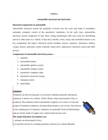
NFPA VOLUME 70 NATIONAL ELECTRICAL CODEConcrete-Encased ElectrodesIntroduction: The 1965 edition of the National Electrical Code, as pictured below, made no referenceto a “Made Electrode” called a “Concrete Encased Electrode”.NFPA Volume-70 1965 Edition of the National Electrical CodeChapter 2. Wiring Design and ProtectionArticle 250 GroundingPart H. Grounding ElectrodesSection 250-83 – Subsection (a) through (d)Page 1 of 8.
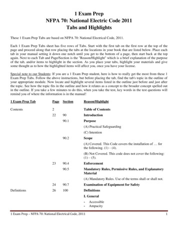
Introduction: The 1968 edition of the National Electrical Code, as pictured below, made the firstreference to a “Made Electrode” called a “Concrete Encased Electrode”.NFPA Volume-70 1968 Edition of the National Electrical CodeChapter 2. Wiring Design and ProtectionArticle 250 GroundingPart H. Grounding ElectrodesSection 250-83 – Subsection (a) through (e)Page 2 of 8.
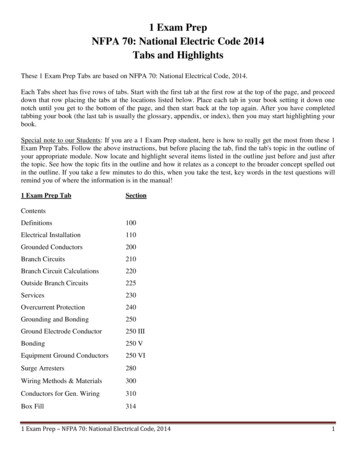
Introduction: The 2011 edition of the National Electrical Code, as pictured below, show the current,State of Texas adopted, reference to the “Concrete Encased Electrode”.NFPA Volume-70 2011 Edition of the National Electrical CodeChapter 2. Wiring Design and ProtectionArticle 250 GroundingPart III. Grounding Electrodes and Grounding Electrode ConductorSection 250.52 Grounding Electrodes. – Subsection (A) Electrodes Permitted for Grounding.Sub-section (3) Concrete-Encased Electrode.Page 3 of 8.
Purpose of this PresentationThe National Electrical Code has recognized a “Made Electrode” called a “Concrete-EncasedElectrode” since the Code year 1968. The description of this electrode is worded in the exhibitspictured above which was produced directly from the National Electrical Code. One of the mostimportant specifications of the Concrete-Encased Electrode is its “direct contact with earth”. The directcontact with earth is the primary reason the installation is effective in providing a qualified groundconnection. The National Electrical Code in Article 100 – Definitions, defines “Ground” as earth.A properly installed Concrete-Encased Electrode provides an excellent grounding point, asrequired by the National Electrical Code, for Safety in an electrical system. However an improperlyinstalled Concrete-Encased Electrode will provide an electrical hazard. This is why it is imperative thatall electrical personal and inspectors understand and properly enforce the National Electrical Code.The knowledge and information necessary to comply with the rules pertaining to “ConcreteEncased Electrodes” have been grossly misunderstood and misapplied due to the way our homes andother buildings are constructed in our area (Houston) of the State of Texas. Due to the problem ofground moisture entering our structures, products called insulation, vapor barriers, films, and similaritems must be installed between the earth and the concrete slab. Building Codes require this type ofinstallation and Builders are required to comply.This compliance with mandatory Building Codes presents a big problem with electrical groundingwhen a grounding installation, relying on a Concrete-Encased Electrode, is employed. Simplyexplained, the insulation, vapor barriers, films, and similar items act as “Electrical Insulators”preventing necessary contact between the concrete slab and the earth. This contact is necessary toensure a low resistance path to ground (earth) for safety in the electrical system.The continued improper understanding of Concrete-Encased Electrode installations prompted theNFPA (National Fire Protection Association) to add an “Informational Note:” to the 2011 edition ofthe National Electrical Code. This informational note is shown on Page 3 of this presentation. The noteinforms the electrical installer that “direct contact” with the earth is NOT achieved, as required byCode, when insulation, vapor barriers, films, and similar items are installed separating the slab fromdirect contact with the earth. Therefore the National Electrical Code DOES NOT “Consider” this typeof installation as qualified to serve as a ”Concrete-Encased Electrode”.Some jurisdictions, enforcing electrical installations, do not agree with the National Electrical Codeon this issue and basic electrical technology knowledge presented by the “Informational Note:” to the2011 edition of the National Electrical Code. Therefore many improper grounding installations exist inhomes built today.In this presentation, I have endeavored to present the issue of ”Concrete-Encased Electrodes” as itexists in the electrical construction industry today.The purpose of the National Electrical Code is “the practical safeguarding of persons and propertyfrom hazards arising from the use of electricity” as quoted from Article 90, Section 90.1(A) of the 2011National Electrical Code. The use of a concrete slab installation as a ”Concrete-Encased Electrode”when insulation, vapor barriers, films, and similar items are installed is a direct violation of theNational Electrical Code and should not be allowed.Page 4 of 8.
The following information was taken from a remarkable article found at the following site. For thecomplete article please go ounding-electrodes.phpE & S Grounding Solutions - About Electrical GroundingWhat Are Some Different Types of Grounding Electrodes?Ufer Ground or Concrete Encased ElectrodesOriginally, Ufer grounds were copper electrodes encased in the concrete surrounding ammunitionbunkers. In today’s terminology, Ufer grounds consist of any concrete-encased electrode, such as therebar in a building foundation, when used for grounding, or a wire or wire mesh in concrete.Concrete Encased ElectrodeThe National Electrical Code requires that Concrete Encased Electrodes use a minimum No. 4AWG copper wire at least 20 feet in length and encased in at least 2 inches of concrete. The advantagesof concrete encased electrodes are that they dramatically increase the surface area and degree ofcontact with the surrounding soil. However, the zone of influence is not increased, therefore theresistance to ground is typically only slightly lower than the wire would be without the concrete.Concrete encased electrodes also have some significant disadvantages. When an electrical faultoccurs, the electric current must flow through the concrete into the earth. Concrete, by nature retains alot of water, which rises in temperature as the electricity flows through the concrete. If the extent of theelectrode is not sufficiently great for the total current flowing, the boiling point of the water may bereached, resulting in an explosive conversion of water into steam. Many concrete encased electrodeshave been destroyed after receiving relatively small electrical faults. Once the concrete cracks apartand falls away from the conductor, the concrete pieces act as a shield preventing the copper wire fromcontacting the surrounding soil, resulting in a dramatic increase in the resistance-to-ground of theelectrode.Page 5 of 8.
There are many new products available on the market designed to improve concrete encasedelectrodes. The most common are modified concrete products that incorporate conductive materialsinto the cement mix, usually carbon. The advantage of these products is that they are fairly effective inreducing the resistivity of the concrete, thus lowering the resistance-to-ground of the electrodeencased. The most significant improvement of these new products is in reducing heat buildup in theconcrete during fault conditions, which can lower the chances that steam will destroy the concreteencased electrode. However some disadvantages are still evident. Again, these products do notincrease the zone-of-influence and as such the resistance-to-ground of the concrete encased electrode isonly slightly better than what a bare copper wire or driven rod would be in the ground. Also aprimary concern regarding enhanced grounding concretes is the use of carbon in the mix. Carbon andcopper are of different nobilities and will sacrificially corrode each other over time. Many of theseproducts claim to have buffer materials designed to reduce the accelerated corrosion of the coppercaused by the addition of carbon into the mix. However, few independent long-term studies are beingconducted to test these claims.Ufer Ground or Building FoundationsUfer Grounds or building foundations may be used provided that the concrete is in direct contactwith the earth (no plastic moisture barriers), that rebar is at least 0.500 inches in diameter and thatthere is a direct metallic connection from the service ground to the rebar buried inside the concrete.This concept is based on the conductivity of the concrete and the large surface area, which willusually provide a grounding system that, can handle very high current loads. The primary drawbackoccurs during fault conditions, if the fault current is too great compared with the area of the rebarsystem, when moisture in the concrete superheats and rapidly expands, cracking the surroundingconcrete and the threatening the integrity of the building foundation. Another drawback to the Uferground is they are not testable under normal circumstances as isolating the concrete slab in order toproperly perform resistance-to-ground testing is nearly impossible.Page 6 of 8.
The metal frame of a building may also be used as a grounding point, provided that the buildingfoundation meets the above requirements, and is commonly used in high-rise buildings. It should benoted that many owners of these high-rise buildings are banning this practice and insisting thattenants run ground wires all the way back to the secondary service locations on each floor. The ownerswill have already run ground wires from the secondary services back to the primary service locationsand installed dedicated grounding systems at these service locations. The goal is to avoid the flow ofstray currents, which can interfere with the operation of sensitive electronic equipment.How To Do Grounding System TestingThe measurement of ground resistance for an earth electrode system is very important. It should bedone when the electrode is first installed, and then at periodic intervals thereafter. This ensures thatthe resistance-to-ground does not increase over time. There are two (2) methods for testing an existingearth-electrode system. The first is the 3-point or Fall-of- Potential method and the second is theInduced Frequency test or clamp-on method. The 3-point test requires complete isolation from thepower utility. Not just power isolation, but also removal of any neutral or other such groundconnections extending outside the grounding system. This test is the most suitable test for largegrounding systems and is also suitable for small electrodes. The induced frequency test can beperformed while power is on and actually requires the utility to be connected to the grounding systemunder test. This test is accurate only for small electrodes, as it uses frequencies in the kilo Hertz range,which see long conductors as inductive chokes and therefore do not reflect the 60 Hz resistance of theentire grounding system.Fall-of-Potential Method or 3-Point TestThe 3-point or fall-of-potential method is used to measure the resistance-to-ground of existinggrounding systems. The two primary requirements to successfully complete this test are the ability toisolate the grounding system from the utility neutral and knowledge of the diagonal length of thegrounding system (i.e. a 10’ x 10’ grounding ring would have a 14’ diagonal length). In this test, a shortprobe, referred to as probe Z, is driven into the earth at a distance of ten times (10X) the diagonallength of the grounding system (rod X). A second probe (Y) is placed in-line at a distance from rod Xequal to the diagonal length of the grounding system.Page 7 of 8.
At this point, a known current is applied across X & Z, while the resulting voltage is measuredacross X & Y. Ohm’s Law can then be applied (R V/I) to calculate the measured resistance. Probe Y isthen moved out to a distance of 2X the diagonal length of the grounding system, in-line with X & Z, torepeat the resistance measurement at the new interval. This will continue, moving probe Y out to 3X,4X, . 9X the diagonal length to complete the 3–point test with a total of nine (9) resistancemeasurements.Graphing & EvaluationThe 3-point test is evaluated by plotting the results as data points with the distance from rod Xalong the X-axis and the resistance measurements along the Y-axis to develop a curve. Roughlymidway between the center of the electrode under test and the probe Z, a plateau or “flat spot” shouldbe found, as shown in the graph. The resistance of this plateau (actually, the resistance measured at thelocation 62% from the center of the electrode under test, if the soil is perfectly homogeneous) is theresistance-to-ground of the tested grounding system.Invalid TestsIf no semblance of a plateau is found and the graph is observed to rise steadily the test isconsidered invalid. This can be due to the fact that probe Z was not placed far enough away from rodX, and can usually indicate that the diagonal length of the grounding system was not determinedcorrectly. If the graph is observed to have a low plateau that extends the entire length and only rises atthe last test point, then this also may be also considered invalid. This is because the utility or telecomneutral connection remains on the grounding system.Wayne RogersEducator/ConsultantPage 8 of 8.
NFPA Volume-70 2011 Edition of the National Electrical Code Chapter 2. Wiring Design and Protection Article 250 Grounding Part III. Grounding Electrodes and Grounding Electrode Conductor Section 250.52 Grounding Electrodes. – Subsection (A) Electrodes Permitted for Grounding. Sub-section (3) Concrete-Encased Electrode. Page 3 of 8. Purpose of this Presentation The National Electrical Code .File Size: 1MBPage Count: 8People also search fornfpa 79nfpa 70 article 500step voltage testnfpa 70 free download pdfnfpa 70 article 500nfpa 70 pdf