Transcription
1HEAT TRANSFER EQUATION SHEETHeat Conduction Rate Equations (Fourier's Law)𝑑𝑑𝑑𝑑𝑊𝑊𝑊𝑊 Heat Flux: 𝑞𝑞𝑥𝑥′′ 𝑘𝑘𝑑𝑑𝑑𝑑𝑚𝑚2′′ Heat Rate: 𝑞𝑞𝑥𝑥 𝑞𝑞𝑥𝑥 𝐴𝐴𝑐𝑐𝑊𝑊Heat Convection Rate Equations (Newton's Law of Cooling)𝑊𝑊 Heat Flux: 𝑞𝑞′′ ℎ(𝑇𝑇𝑠𝑠 𝑇𝑇 )𝑚𝑚2 Heat Rate: 𝑞𝑞 ℎ𝐴𝐴𝑠𝑠 (𝑇𝑇𝑠𝑠 𝑇𝑇 ) 𝑊𝑊k : Thermal Conductivity 𝑚𝑚 𝑘𝑘Ac : Cross-Sectional Area𝑊𝑊h : Convection Heat Transfer Coefficient 𝑚𝑚2 𝐾𝐾As : Surface Area 𝑚𝑚2Heat Radiation emitted ideally by a blackbody surface has a surface emissive power: 𝐸𝐸𝑏𝑏 𝜎𝜎 𝑇𝑇𝑠𝑠4 Heat Flux emitted: 𝐸𝐸 𝜀𝜀𝜀𝜀𝑇𝑇𝑠𝑠4𝑊𝑊𝑚𝑚2 8𝑊𝑊𝑚𝑚2where ε is the emissivity with range of 0 𝜀𝜀 1𝑊𝑊and 𝜎𝜎 5.67 10is the Stefan-Boltzmann constant𝑚𝑚2 𝐾𝐾44 Irradiation: 𝐺𝐺𝑎𝑎𝑎𝑎𝑎𝑎 𝛼𝛼𝛼𝛼 but we assume small body in a large enclosure with 𝜀𝜀 𝛼𝛼 so that 𝐺𝐺 𝜀𝜀 𝜎𝜎 𝑇𝑇𝑠𝑠𝑠𝑠𝑠𝑠𝑞𝑞′′4 ) Net Radiation heat flux from surface: 𝑞𝑞𝑟𝑟𝑟𝑟𝑟𝑟 𝜀𝜀𝐸𝐸𝑏𝑏 (𝑇𝑇𝑠𝑠 ) 𝛼𝛼𝛼𝛼 𝜀𝜀𝜀𝜀(𝑇𝑇𝑠𝑠4 𝑇𝑇𝑠𝑠𝑠𝑠𝑠𝑠𝐴𝐴4 Net radiation heat exchange rate: 𝑞𝑞𝑟𝑟𝑟𝑟𝑟𝑟 𝜀𝜀𝜀𝜀𝐴𝐴𝑠𝑠 (𝑇𝑇𝑠𝑠4 𝑇𝑇𝑠𝑠𝑠𝑠𝑠𝑠) where for a real surface 0 𝜀𝜀 1This can ALSO be expressed as: 𝑞𝑞𝑟𝑟𝑟𝑟𝑟𝑟 ℎ𝑟𝑟 𝐴𝐴(𝑇𝑇𝑠𝑠 𝑇𝑇𝑠𝑠𝑠𝑠𝑠𝑠 ) depending on the application𝑊𝑊2 )where ℎ𝑟𝑟 is the radiation heat transfer coefficient which is: ℎ𝑟𝑟 𝜀𝜀𝜀𝜀(𝑇𝑇𝑠𝑠 𝑇𝑇𝑠𝑠𝑠𝑠𝑠𝑠 )(𝑇𝑇𝑠𝑠2 𝑇𝑇𝑠𝑠𝑠𝑠𝑠𝑠𝑚𝑚2 𝐾𝐾44 TOTAL heat transfer from a surface: 𝑞𝑞 𝑞𝑞𝑐𝑐𝑐𝑐𝑐𝑐𝑐𝑐 𝑞𝑞𝑟𝑟𝑟𝑟𝑟𝑟 ℎ𝐴𝐴𝑠𝑠 (𝑇𝑇𝑠𝑠 𝑇𝑇 ) 𝜀𝜀𝜀𝜀𝐴𝐴𝑠𝑠 (𝑇𝑇𝑠𝑠 𝑇𝑇𝑠𝑠𝑠𝑠𝑠𝑠 ) 𝑊𝑊Conservation of Energy (Energy Balance)𝐸𝐸̇𝑖𝑖𝑖𝑖 𝐸𝐸𝑔𝑔̇ 𝐸𝐸̇𝑜𝑜𝑜𝑜𝑜𝑜 𝐸𝐸̇𝑠𝑠𝑠𝑠 (Control Volume Balance) ; 𝐸𝐸̇𝑖𝑖𝑖𝑖 𝐸𝐸̇𝑜𝑜𝑜𝑜𝑜𝑜 0 (Control Surface Balance)where 𝐸𝐸𝑔𝑔̇ is the conversion of internal energy (chemical, nuclear, electrical) to thermal or mechanical energy, and𝑑𝑑𝑑𝑑𝐸𝐸̇𝑠𝑠𝑠𝑠 0 for steady-state conditions. If not steady-state (i.e., transient) then 𝐸𝐸̇𝑠𝑠𝑠𝑠 𝜌𝜌𝜌𝜌𝑐𝑐𝑝𝑝Heat Equation (used to find the temperature distribution) Heat Equation (Cartesian): 𝑘𝑘 If 𝑘𝑘 is constant then the above simplifies to:Heat Equation (Cylindrical):Heat Eqn. (Spherical):1 𝑟𝑟 1 𝑟𝑟 2 𝑘𝑘𝑘𝑘 𝑘𝑘𝑟𝑟 2Plane Wall: 𝑅𝑅𝑡𝑡,𝑐𝑐𝑐𝑐𝑐𝑐𝑐𝑐 𝐿𝐿 𝑘𝑘𝑘𝑘 𝑘𝑘 2 𝑇𝑇 𝑥𝑥 2 2 𝑇𝑇 𝑦𝑦1 𝑟𝑟 2 1 2 𝑘𝑘𝑟𝑟 2 sin 𝜃𝜃 2 𝑘𝑘 2 𝑇𝑇 𝑧𝑧 2 𝑞𝑞̇1 𝛼𝛼 𝑘𝑘 Thermal CircuitsCylinder: 𝑅𝑅𝑡𝑡,𝑐𝑐𝑐𝑐𝑐𝑐𝑐𝑐 𝑞𝑞̇ 𝜌𝜌𝑐𝑐𝑝𝑝 𝑘𝑘 𝑟𝑟 𝑘𝑘12𝜋𝜋𝜋𝜋𝜋𝜋 where 𝛼𝛼 𝑘𝑘𝜌𝜌𝑐𝑐𝑝𝑝 𝑞𝑞̇ 𝜌𝜌𝑐𝑐𝑝𝑝𝑟𝑟 2 sin 𝜃𝜃ln 2 𝑟𝑟1 𝑑𝑑𝑑𝑑 𝑘𝑘 sin 𝜃𝜃is the thermal diffusivity 𝑞𝑞̇ 𝜌𝜌𝑐𝑐𝑝𝑝Sphere: 𝑅𝑅𝑡𝑡,𝑐𝑐𝑐𝑐𝑐𝑐𝑐𝑐 1 1r1 r2( )4𝜋𝜋𝜋𝜋
𝑅𝑅𝑡𝑡,𝑐𝑐𝑐𝑐𝑐𝑐𝑐𝑐 1𝑅𝑅𝑡𝑡,𝑟𝑟𝑟𝑟𝑟𝑟 ℎ𝐴𝐴21ℎ𝑟𝑟 𝐴𝐴General Lumped Capacitance Analysis4 )]𝑞𝑞𝑠𝑠′′ 𝐴𝐴𝑠𝑠,ℎ 𝐸𝐸𝑔𝑔̇ [ℎ(𝑇𝑇 𝑇𝑇 ) 𝜀𝜀𝜀𝜀(𝑇𝑇 4 ���𝑐,𝑟𝑟) 𝜌𝜌𝜌𝜌𝜌𝜌Radiation Only Equation𝑡𝑡 𝜌𝜌𝜌𝜌𝜌𝜌4 𝜀𝜀 𝐴𝐴𝑠𝑠,𝑟𝑟 𝜎𝜎3𝑇𝑇𝑠𝑠𝑠𝑠𝑠𝑠 ln 𝑏𝑏𝑏𝑏𝑇𝑇𝑖𝑖 𝑇𝑇 ��𝑠𝑠 𝑇𝑇 ln 𝑇𝑇𝑠𝑠𝑠𝑠𝑠𝑠 𝑇𝑇𝑖𝑖𝑇𝑇𝑠𝑠𝑠𝑠𝑠𝑠 𝑇𝑇𝑖𝑖𝑇𝑇 2 tan 1 𝑇𝑇𝑠𝑠𝑠𝑠𝑠𝑠 tan 1 exp( 𝑎𝑎𝑎𝑎) ; where 𝑎𝑎 ��Convection Only Equation and 𝑏𝑏 𝑇𝑇 𝑇𝑇 ℎ𝐴𝐴𝑠𝑠𝜃𝜃 exp 𝑡𝑡 𝜃𝜃𝑖𝑖 𝑇𝑇𝑖𝑖 𝑇𝑇 𝜌𝜌𝜌𝜌𝜌𝜌 (𝜌𝜌𝜌𝜌𝜌𝜌) 𝑅𝑅𝑡𝑡 𝐶𝐶𝑡𝑡;𝑡𝑡𝑄𝑄 𝜌𝜌𝜌𝜌𝜌𝜌 𝜃𝜃𝑖𝑖 1 exp 𝐵𝐵𝐵𝐵 ��𝑇𝑇𝑠𝑠𝑠𝑠𝑠𝑠Heat Flux, Energy Generation, Convection, and No Radiation Equation𝑇𝑇 𝑇𝑇 𝑎𝑎𝜏𝜏𝑡𝑡 𝑇𝑇𝑠𝑠𝑠𝑠𝑠𝑠 𝑇𝑇𝑑𝑑𝑑𝑑𝑑𝑑𝑑𝑑 𝑞𝑞𝑠𝑠′′ 𝐴𝐴𝑠𝑠,ℎ 𝑚𝑚𝑚𝑚𝑚𝑚 𝜌𝜌𝜌𝜌𝜌𝜌 𝜃𝜃𝑖𝑖𝑘𝑘If there is an additional resistance either in series or in parallel, then replace ℎ with 𝑈𝑈 in all the above lumped capacitanceequations, where𝑈𝑈 1𝑅𝑅𝑡𝑡 𝐴𝐴𝑠𝑠 𝑅𝑅𝑅𝑅 𝑊𝑊𝑚𝑚2 𝐾𝐾 𝜌𝜌𝜌𝜌𝐿𝐿𝑐𝑐𝜇𝜇; 𝑈𝑈 overall heat transfer coefficient, 𝑅𝑅𝑡𝑡 total resistance, 𝐴𝐴𝑠𝑠 surface area.Convection Heat Transfer 𝑉𝑉𝐿𝐿𝑐𝑐𝜈𝜈[Reynolds Number]; ℎ𝐿𝐿 𝑁𝑁𝑁𝑁 𝑐𝑐𝑘𝑘𝑓𝑓[Average Nusselt Number]where 𝜌𝜌 is the density, 𝑉𝑉 is the velocity, 𝐿𝐿𝑐𝑐 is the characteristic length, 𝜇𝜇 is the dynamic viscosity, 𝜈𝜈 is the kinematic viscosity, 𝑚𝑚̇ is the mass flowrate, ℎ is the average convection coefficient, and 𝑘𝑘𝑓𝑓 is the fluid thermal conductivity.
𝑅𝑅𝑅𝑅 3Internal Flow4 𝑚𝑚̇[For Internal Flow in a Pipe of Diameter D]𝜋𝜋𝜋𝜋𝜋𝜋For Constant Heat Flux [𝑞𝑞𝑠𝑠ʺ ��𝑐 𝑞𝑞𝑠𝑠ʺ (𝑃𝑃 𝐿𝐿) ; where P Perimeter, L Length𝑞𝑞𝑠𝑠ʺ · 𝑃𝑃𝑥𝑥𝑇𝑇𝑚𝑚 (𝑥𝑥) 𝑇𝑇𝑚𝑚,𝑖𝑖 𝑚𝑚̇ 𝑐𝑐𝑝𝑝For Constant Surface Temperature [𝑇𝑇𝑠𝑠 ��𝑐𝑐𝑐]:If there is only convection between the surface temperature, 𝑇𝑇𝑠𝑠 , and the mean fluid temperature, 𝑇𝑇𝑚𝑚 , use𝑇𝑇𝑠𝑠 𝑇𝑇𝑚𝑚 (𝑥𝑥) 𝑒𝑒𝑒𝑒𝑒𝑒 𝑇𝑇𝑠𝑠 𝑇𝑇𝑚𝑚,𝑖𝑖𝑃𝑃 𝑥𝑥𝑚𝑚̇ 𝑐𝑐𝑝𝑝ℎ If there are multiple resistances between the outermost temperature, 𝑇𝑇 , and the mean fluid temperature, 𝑇𝑇𝑚𝑚 , use𝑇𝑇 𝑇𝑇𝑚𝑚 (𝑥𝑥)𝑃𝑃 𝑥𝑥1 𝑒𝑒𝑒𝑒𝑒𝑒 𝑈𝑈 𝑒𝑒𝑒𝑒𝑒𝑒 𝑇𝑇 𝑇𝑇𝑚𝑚,𝑖𝑖𝑚𝑚̇ 𝑐𝑐𝑝𝑝𝑚𝑚̇ 𝑐𝑐𝑝𝑝 𝑅𝑅𝑡𝑡Total heat transfer rate over the entire tube length:𝑞𝑞𝑡𝑡 𝑚𝑚̇ 𝑐𝑐𝑝𝑝 𝑇𝑇𝑚𝑚,𝑜𝑜 𝑇𝑇𝑚𝑚,𝑖𝑖 ℎ 𝐴𝐴𝑠𝑠 𝑇𝑇𝑙𝑙𝑙𝑙 𝑜𝑜𝑜𝑜 𝑈𝑈 𝐴𝐴𝑠𝑠 𝑇𝑇𝑙𝑙𝑙𝑙Log mean temperature difference: 𝑇𝑇𝑙𝑙𝑙𝑙 𝑇𝑇𝑜𝑜 𝑇𝑇𝑖𝑖; 𝑇𝑇𝑠𝑠 ��𝑐𝑐𝑐; 𝑇𝑇𝑜𝑜 𝑇𝑇𝑠𝑠 𝑇𝑇𝑚𝑚,𝑜𝑜 ; 𝑇𝑇𝑖𝑖 𝑇𝑇𝑠𝑠 𝑇𝑇𝑚𝑚,𝑖𝑖 𝑇𝑇𝑜𝑜 𝑇𝑇𝑖𝑖ln Free Convection Heat Transfer𝐺𝐺𝐺𝐺𝐿𝐿 𝑅𝑅𝑅𝑅𝐿𝐿 Vertical Plates: 𝑁𝑁𝑁𝑁𝐿𝐿 0.825 𝑔𝑔𝑔𝑔(𝑇𝑇𝑠𝑠 𝑇𝑇 )𝐿𝐿3𝑐𝑐[Grashof Number]𝑔𝑔𝑔𝑔(𝑇𝑇𝑠𝑠 𝑇𝑇 )𝐿𝐿3𝑐𝑐[Rayleigh Number]𝜈𝜈2𝜈𝜈𝜈𝜈0.387 𝑅𝑅𝑅𝑅𝐿𝐿 1 1/60.492 9/16 𝑃𝑃𝑃𝑃8/272 ; [Entire range of RaL; properties evaluated at Tf ]- For better accuracy for Laminar Flow: 𝑁𝑁𝑁𝑁𝐿𝐿 0.68 1/40.670 𝑅𝑅𝑅𝑅𝐿𝐿0.492 9/16 1 𝑃𝑃𝑃𝑃4/9; 𝑅𝑅𝑅𝑅𝐿𝐿 109 [Properties evaluated at Tf ]Inclined Plates: for the top and bottom surfaces of cooled and heated inclined plates, respectively, the equations of the verticalplate can be used by replacing (g) with (𝑔𝑔 cos 𝜃𝜃) in RaL for 0 𝜃𝜃 60 .Horizontal Plates: use the following correlations with 𝐿𝐿 𝐴𝐴𝑠𝑠𝑃𝑃where As Surface Area and P Perimeter- Upper surface of Hot Plate or Lower Surface of Cold Plate:1/41/3 𝑁𝑁𝑁𝑁𝐿𝐿 0.54 𝑅𝑅𝑅𝑅𝐿𝐿 (104 𝑅𝑅𝑅𝑅𝐿𝐿 107 , 𝑃𝑃𝑃𝑃 0.7) ; 𝑁𝑁𝑁𝑁𝐿𝐿 0.15 𝑅𝑅𝑅𝑅𝐿𝐿 (107 𝑅𝑅𝑅𝑅𝐿𝐿 1011 , 𝑎𝑎𝑎𝑎𝑎𝑎 𝑃𝑃𝑃𝑃)- Lower Surface of Hot Plate or Upper Surface of Cold Plate: 𝐿𝐿 0.52 𝑅𝑅𝑅𝑅1/5𝑁𝑁𝑁𝑁𝐿𝐿(104 𝑅𝑅𝑅𝑅𝐿𝐿 109 , 𝑃𝑃𝑃𝑃 0.7)
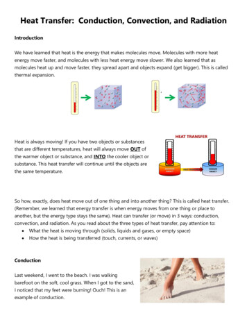
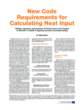
Vertical Cylinders: the equations for the Vertical Plate can be applied to vertical cylinders of height L if the following criterion ismet:𝐷𝐷𝐿𝐿 351/4𝐺𝐺𝐺𝐺𝐿𝐿Long Horizontal Cylinders: 𝑁𝑁𝑁𝑁𝐷𝐷 0.60 Spheres: 𝑁𝑁𝑁𝑁𝐷𝐷 2 1/40.589 𝑅𝑅𝑅𝑅𝐷𝐷4/90.469 9/16 1 𝑃𝑃𝑃𝑃 1/60.387 𝑅𝑅𝑅𝑅𝐷𝐷8/270.559 9/16 1 𝑃𝑃𝑃𝑃 2; 𝑅𝑅𝑅𝑅𝐷𝐷 1012 [Properties evaluated at Tf ]; 𝑅𝑅𝑅𝑅𝐷𝐷 1011 ; 𝑃𝑃𝑃𝑃 0.7 [Properties evaluated at Tf ]Heat ExchangersHeat Gain/Loss Equations:𝑞𝑞 𝑚𝑚̇ 𝑐𝑐𝑝𝑝 (𝑇𝑇𝑜𝑜 𝑇𝑇𝑖𝑖 ) 𝑈𝑈𝐴𝐴𝑠𝑠 𝑇𝑇𝑙𝑙𝑙𝑙 ; where 𝑈𝑈 is the overall heat transfercoefficient and As is the total heat exchanger surface areaLog-Mean Temperature Difference: 𝑇𝑇𝑙𝑙𝑙𝑙,𝑃𝑃𝑃𝑃 𝑇𝑇ℎ,𝑖𝑖 𝑇𝑇𝑐𝑐,𝑖𝑖 𝑇𝑇ℎ,𝑜𝑜 𝑇𝑇𝑐𝑐,𝑜𝑜 [Parallel-Flow Heat Exchanger]Log-Mean Temperature Difference: 𝑇𝑇𝑙𝑙𝑙𝑙,𝐶𝐶𝐶𝐶 𝑇𝑇ℎ,𝑖𝑖 𝑇𝑇𝑐𝑐,𝑜𝑜 𝑇𝑇ℎ,𝑜𝑜 𝑇𝑇𝑐𝑐,𝑖𝑖 [Counter-Flow Heat Exchanger]ln For Cross-Flow and Shell-and-Tube Heat Exchangers:obtained from the figures by calculating P & R valuesEffectiveness – NTU Method (ε – NTU):Number of Transfer Units (NTU): 𝑁𝑁𝑁𝑁𝑁𝑁 𝑈𝑈𝑈𝑈𝐶𝐶𝑚𝑚𝑚𝑚𝑚𝑚 𝑇𝑇ℎ,𝑖𝑖 𝑇𝑇𝑐𝑐,𝑖𝑖 𝑇𝑇ℎ,𝑜𝑜 𝑇𝑇𝑐𝑐,𝑜𝑜 𝑇𝑇ℎ,𝑖𝑖 𝑇𝑇𝑐𝑐,𝑜𝑜 ln 𝑇𝑇ℎ,𝑜𝑜 𝑇𝑇𝑐𝑐,𝑖𝑖 𝑇𝑇𝑙𝑙𝑙𝑙 𝐹𝐹 𝑇𝑇𝑙𝑙𝑙𝑙,𝐶𝐶𝐶𝐶 ; where 𝐹𝐹 is a correction factor; where 𝐶𝐶𝑚𝑚𝑚𝑚𝑚𝑚 is the minimum heat capacity rate in [W/K]Heat Capacity Rates: 𝐶𝐶𝑐𝑐 𝑚𝑚̇𝑐𝑐 𝑐𝑐𝑝𝑝,𝑐𝑐 [Cold Fluid] ; 𝐶𝐶ℎ 𝑚𝑚̇ℎ 𝑐𝑐𝑝𝑝,ℎ [Hot Fluid]𝐶𝐶𝑟𝑟 ��𝑚𝑚𝑚[Heat Capacity Ratio]Note: The condensation or evaporation side of the heat exchanger is associated with 𝐶𝐶𝑚𝑚𝑚𝑚𝑚𝑚 𝑞𝑞 𝑚𝑚̇𝑐𝑐 𝐶𝐶𝑝𝑝,𝑐𝑐 𝑇𝑇𝑐𝑐,𝑜𝑜 𝑇𝑇𝑐𝑐,𝑖𝑖 𝑚𝑚̇ℎ 𝐶𝐶𝑝𝑝,ℎ 𝑇𝑇ℎ,𝑖𝑖 𝑇𝑇ℎ,𝑜𝑜 𝑈𝑈𝐴𝐴𝑠𝑠 ��𝑚 𝐶𝐶𝑚𝑚𝑚𝑚𝑚𝑚 𝑇𝑇ℎ,𝑖𝑖 𝑇𝑇𝑐𝑐,𝑖𝑖 where𝜀𝜀 𝑞𝑞𝑞𝑞𝑚𝑚𝑚𝑚𝑚𝑚Use: 𝜀𝜀 𝑓𝑓(𝑁𝑁𝑁𝑁𝑁𝑁, 𝐶𝐶𝑟𝑟 ) relations or 𝑁𝑁𝑁𝑁𝑁𝑁 𝑓𝑓(𝜀𝜀, 𝐶𝐶𝑟𝑟 ) relations as appropriate4
5
6If Pr 10 n 0.37If Pr 10 n 0.36
7
8
9
10
11
12
13
14
15
16
17
18
19
20
21
22
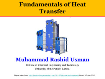
Page 726Chapter 11䊏Heat Exchangers1.01.0mi /n Cmax .500.751.000min /Cmax 00.83NTU405FIGURE 11.10 Effectiveness of a parallelflow heat exchanger (Equation 11.28).0123NTU45FIGURE 11.11 Effectiveness of acounterflow heat exchanger (Equation 11.29).Th,i or Tc,iTc,o or Th,oTh,i or Tc,iTc,o or Th,oTc,i or Th,iTc,i or Th,iTh,o or Tc,oTh,o or Tc,o1.01.00.80.751.000.6 01.000.750.500.25ε0.60.50axmC0.8min /C0.25min /Cmax 0C7265:21 E 11.12 Effectiveness of a shell-andtube heat exchanger with one shell and anymultiple of two tube passes (two, four, etc.tube passes) (Equation 11.30).0123NTU45FIGURE 11.13 Effectiveness of a shell-andtube heat exchanger with two shell passes andany multiple of four tube passes (four, eight,etc. tube passes) (Equation 11.31 with n 2).
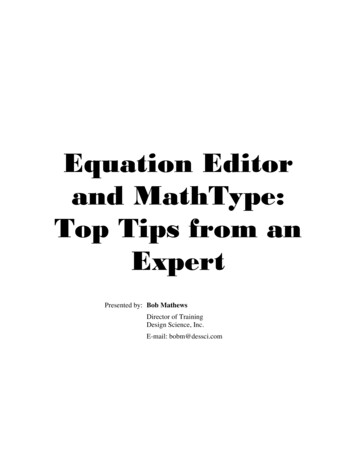
Page 72711.4䊏Th,i or Tc,iTc,i or Th,iTh,i or Tc,iTc,o or Th,oTc,i or Th,iTc,o or Th,oTh,o or Tc,oTh,o or Tc,o1.01.0axm 0mixed /Cunm0.80.80.40.20123NTU45FIGURE 11.14 Effectiveness of a singlepass, cross-flow heat exchanger with bothfluids unmixed (Equation 11.32). 0, 7Heat Exchanger Analysis: The Effectiveness–NTU Methodmin /C5:21 NTU45FIGURE 11.15 Effectiveness of a singlepass, cross-flow heat exchanger with one fluidmixed and the other unmixed (Equations11.33, 11.34).
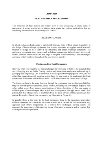
1/19/064:57 PMPage W-37Chapter 11 Supplemental Material11S.1Log Mean Temperature DifferenceMethod for Multipass and Cross-FlowHeat ExchangersAlthough flow conditions are more complicated in multipass and cross-flow heatexchangers, Equations 11.6, 11.7, 11.14, and 11.15 may still be used if the following modification is made to the log mean temperature difference [1]: Tlm F Tlm,CF(11S.1)That is, the appropriate form of Tlm is obtained by applying a correction factor tothe value of Tlm that would be computed under the assumption of counterflow conditions. Hence from Equation 11.17, T1 Th,i Tc,o and T2 Th,o Tc,i.Algebraic expressions for the correction factor F have been developed for various shell-and-tube and cross-flow heat exchanger configurations [1–3], and theresults may be represented graphically. Selected results are shown in Figures 11S.1through 11S.4 for common heat exchanger configurations. The notation (T, t) is usedto specify the fluid temperatures, with the variable t always assigned to the tube-sideTitotiTo1.00.90.8Fc11 supl.qxd0.70.60.56.0 4.0 3.02.0 1.51.0 0.8 0.60.40.2Ti – ToR to – ti00.10.20.30.40.50.60.70.80.91.0to – tiP Ti – tiFIGURE 11S.1 Correction factor for a shell-and-tube heat exchangerwith one shell and any multiple of two tube passes (two, four, etc. tubepasses).
W-384:57 PMPage W-3811S.1 Log Mean Temperature Difference MethodTitotiTo1.00.96.0 4.0 3.02.01.0 0.8 0.61.50.40.20.8F1/19/060.70.60.5Ti – ToR to – ti00.10.20.30.40.50.60.70.80.91.0to – tiP Ti – tiFIGURE 11S.2 Correction factor for a shell-and-tube heat exchanger with twoshell passes and any multiple of four tube passes (four, eight, etc. tube passes).TititoTo1.00.94.0 3.00.82.01.51.0 0.80.60.40.80.90.2Fc11 supl.qxd0.7Ti – To0.6 R t – toi0.500.10.20.30.40.50.60.7to – tiP Ti – tiFIGURE 11S.3 Correction factor for a single-pass, cross-flow heatexchanger with both fluids unmixed.1.0
1/19/064:57 PMPage W-3911S.1 W-39Log Mean Temperature Difference MethodTititoTo1.00.90.8Fc11 supl.qxd0.74.0 3.02.0 1.51.0 0.8 0.60.40.2Ti – To0.6 R to – ti0.500.10.20.30.40.50.60.70.80.91.0to – tiP Ti – tiFIGURE 11S.4 Correction factor for a single-pass, cross-flow heatexchanger with one fluid mixed and the other unmixed.fluid. With this convention it does not matter whether the hot fluid or the cold fluidflows through the shell or the tubes. An important implication of Figures 11S.1through 11S.4 is that, if the temperature change of one fluid is negligible, either P orR is zero and F is 1. Hence heat exchanger behavior is independent of the specificconfiguration. Such would be the case if one of the fluids underwent a phase change.
726 Chapter 11 Heat Exchangers 01 2 3 4 5 NTU ε 1.0 0.8 0.6 0.4 0.2 0 1.00 C m in / C m a x a 0.25 0 0.75 0.