Transcription
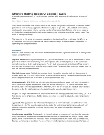
59MN7AInfinityr Modulating4---Way MultipoiseCondensing Gas FurnaceSeries 100Product DataA11263The 59MN7A Multipoise Variable--Capacity Condensing GasFurnace features the modulating InfinityR System. The innovativemodulating gas valve is at the heart of this furnace’s quietoperation, along with the variable--speed ECM blower motor andvariable--speed inducer motor. This furnace also provides 3.5 timestighter temperature control than single stage furnaces. With anAnnual Fuel Utilization Efficiency (AFUE) up to 97.4%, thisInfinity gas furnace provides exceptional savings over standardfurnaces as well. This Infinity Gas Furnace also features 4--waymultipoise installation flexibility. The 59MN7A can be vented as adirect vent/two--pipe furnace or as an optional ventilatedcombustion air application. A Carrier InfinityR Control and anInfinity Air Conditioner or Heat Pump can be used to form acomplete Infinity System. All units meet California Air QualityManagement District emission requirements. All sizes are designcertified in Canada.STANDARD FEATURESS Our quietest furnace. Compare for yourself atHVACpartners.comS Supports single-- and multiple--zone Infinity systemsS Ideal height 35” (889 mm) cabinet: short enough for tallercoils,but still allows enough room for serviceS Infinity Features—match with the Infinity Control for InfinitySystem benefitsS Integral part of the Ideal Humidity SystemR TechnologyS Silicon Nitride Power Heat Hot Surface IgniterS SmartEvap technology helps control humidity levels in thehome when used with a compatible humidity control systemS ComfortFan technology allows control of continuous fanspeed from a compatible thermostatS External Media Filter Cabinet includedS 4--way multipoise design for upflow, downflow or horizontalinstallations, with unique vent elbow and optional through-the--cabinet downflow venting capabilityS Variable--Speed blower and inducer motors, modulating gasvalveS Self--diagnostics and extended diagnostic data through theAdvanced Product Monitor (APM) accessory or Infinity UserInterfaceS Adjustable blower speed for cooling, continuous fan, anddehumidificationS Aluminized--steel primary heat exchangerS Stainless--steel condensing secondary heat exchangerS Propane convertible (See Accessory list).S Factory--configured ready for upflow applicationsS Fully--insulated casing including blower sectionS Convenient Electronic Air Cleaner and Humidifier connectionsS Direct--vent/sealed combustion or ventilated combustion airventingS Installation flexibility: sidewall or vertical ventS Residential installations may be eligible for consumer financingthrough the Retail Credit ProgramLIMITED WARRANTY*S 10 year parts and lifetime heat exchanger limited warranty to theoriginal purchaser upon timely registration.S Limited warranty period is five years for parts and twenty yearsfor the heat exchanger if not registered within 90 days ofinstallation.{* For owner occupied, residential applications.{Jurisdictions where warranty benefits cannot be conditioned on registration will receive registered limited warranty benefits.Always Ask ForCERTIFIED1Use of the AHRI Certified TM Mark indicates amanufacturer’s participation in the program. Forverification of certification for individual products,go to www.ahridirectory.org.
SPECIFICATIONSHeating Capacity and EfficiencyMaximum HeatIntermediate HeatInputMinimum HeatMaximum HeatIntermediate HeatOutputMinimum HeatEfficiencyAFUE % (ICS)Certified TemperatureRise Range ºF (ºC)Airflow Capacity and Blower DataCertified External StaticPressure (in. w.c.)Airflow Delivery@ Rated ESP (CFM)Cooling Capacity (tons)@ 400, 350 CFM/tonDirect-Drive Motor TypeDirect-Drive Motor HPMotor Full Load AmpsRPM RangeSpeed SelectionsBlower Wheel Dia. X WidthAir Filtration SystemFilter Used for Certified Watt DataElectrical DataInput VoltageOperating Voltage RangeMaximum Input AmpsUnit AmpacityMinimum Wire SizeMaximum Wire Length@ Minimum Wire SizeMaximum Fuse/Ckt Bkr(Time-Delay Type Recommended)Transformer Capacity (24vac output)External Control PowerAvailableControlsGas Connection SizeBurners (Monoport)Gas Valve (Redundant)Gas Conversion Kit - Natural to PropaneGas Conversion Kit - Propane to NaturalManufactured (Mobile) Home KitIgnition DeviceLimit ControlHeating Blower Control (Heating Off-Delay)Cooling Blower Control (Time Delay Relay)Communication SystemThermostat ConnectionsAccessory .240 - 7045 - 7545 - 75Maximum Heat(21-38)(25-41)(25-41)50 - 8050 - 8050 - 80Intermediate Heat(27-44)(27-44)(27-44)35 - 6535 - 6535 - 65Minimum 0.150.200.20Cooling0.50.50.5Maximum Heat151015151815Intermediate Heat7509051100Minimum Heat620725900Cooling137520302185400 CFM/ton3.555.5350 CFM/ton45.56Electronically Commutated Motor (ECM)1/21/2117.77.712.812.8300 - 1300Variable (Communicating)in.11 x 811 x 811 x 1011 x 11Factory Supplied Media CabinetField Supplied FilterKGAWF1306UFR KGAWF1306UFR KGAWF1406UFR 460,00039,00024,00059,00038,00024,00097.435 - 65(19-36)50 - 80(27-44)35 020080-14100-20120-2245640 VA27.9 VA27.9 VAHeatingCooling060-141/2” - NPT3ManufacturerMinimum Inlet Gaspressure (in. W.C.)Maximum Inlet Gaspressure (in. W.C.)White Rogers 4.513.61802KGANP5201VSPKGAPN4401VSPnot approved for MH useSilicon Nitride170160Adjustable: 90, 120, 150, 180 seconds90 secondsInfinity; Infinity ZoningW2, Y1, DHUM, G, COM 24V, W/W1, Y/Y2, REAC (115vac); HUM (24vac); 1-stg AC (via Y/Y2)160
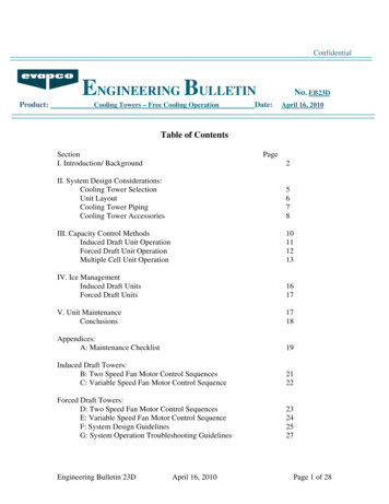
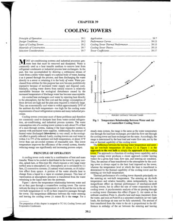
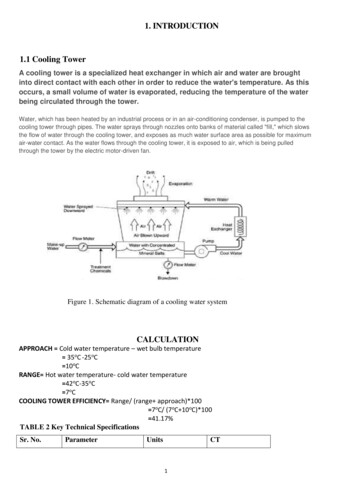
MODEL NUMBER NOMENCLATURE1-2Family593Htg. StagesM4TierN5Effy.76Major SeriesA7-9Htg. Cap.11 - 12Width1710MotorV06013Voltage--14Minor Series--08 - 800 CFM10 - 1000 CFM12 - 1200 CFM14 - 1400 CFM16 - 1600 CFM18 - 1800 CFM20 - 2000 CFM22 - 2200 CFMFamilyS - Single StageT - Two StageM - ModulatingC - ComfortP - PerformanceN - Infinity0 --3 --5 --6 --7 ---14 - 14.2”17 - 17.5”21 - 21.0”24 - 24.5”90 AFUE93 AFUE95 AFUE96 AFUE97 AFUEMajor Series15 - 16Airflow14Minor SeriesVoltage040 40,000 BTU S - Standard060 60,000 BTU E - Energy Efficient080 80,000 BTU V - Variable Speed100 100,000 BTU120 120,000 BTUNot all familes have these models.A11159FURNACE COMPONENTSGAS BURNERHOT SURFACEIGNITERMANUAL RESETROLLOUT SWITCHFLAMESENSORMANUAL RESETROLLOUT SWITCHGAS VALVEMAIN LIMIT SWITCH(BEHIND GAS VALVE)OPERATING INSTRUCTIONSNOT SHOWN (LOCATED ONMAIN FURNACE DOOR, SEEOPERATING INSTRUCTIONSINSIDE DOOR FIGURE).INDUCER MOTORASSEMBLYELECTRICAL JUNCTIONBOX (IF REQUIRED,LOCATION MAY VARY)BLOWER DOORSAFETY SWITCHMEDIA CABINETBLOWER ANDMOTORFURNACECONTROLBOARDCAPACITOR/POWER CHOKE(IF USED)RATING PLATE NOT SHOWN(LOCATED ON BLOWER DOOR)REPRESENTATIVE DRAWING ONLY, SOME MODELS MAY VARY IN APPEARANCE.A114083
ACCESSORIESDESCRIPTIONVenting, Drainage and InstallationVent Kit - Through the CabinetVent Terminal - Concentric - 2” (51 mm)Vent Terminal - Concentric - 3” (76 mm)Vent Terminal Bracket - 2” (51 mm)Vent Terminal Bracket - 3” (76 mm)CPVC to PVC Drain Adapters - 1/2” CPVC to 3/4” PVCHorizontal Trap Grommet - Direct VentFreeze Protect Kit - Heat Patch for Drain TrapFreeze Protect Kit - Heat TapeFurnace Base Kit for Combustible FloorsGas ConversionGas Cnv Kit - Nat to LP; Var-spd ProductsGas Cnv Kit - LP to Nat; Var-spd ProductsGas Orifice Kit - #42 (Nat Gas)Gas Orifice Kit - #43 (Nat Gas)Gas Orifice Kit - #44 (Nat Gas)Gas Orifice Kit - #45 (Nat Gas)Gas Orifice Kit - #46 (Nat Gas)Gas Orifice Kit - #47 (Nat Gas)Gas Orifice Kit - #48 (Nat Gas)Gas Orifice Kit - #54 (LP)Gas Orifice Kit - #55 (LP)Gas Orifice Kit - #56 (LP)Gas Orifice Kit - 1.25mm (LP)Gas Orifice Kit - 1.30mm (LP)Indoor Air QualityCarrier Infinity Air Purifier - 16x25 (406x635 mm)Carrier Infinity Air Purifier - 20x25 (508x635 mm)Carrier Infinity Air Purifier Repl. Filter- 16x25 (406x635 mm)Carrier Infinity Air Purifier Repl. Filter- 20x25 (508x635 mm)EZ Flex Cabinet 16” (406 mm)EZ Flex Cabinet 20” (508 mm)Cartridge Media Filter - 16” (406 mm)Cartridge Media Filter - 20” (508 mm)Cartridge Media Filter - 24” (610 mm)EZ-Flex Filter - 16” (406 mm)EZ-Flex Filter - 20” (508 mm)EZ-Flex Filter - 24” (610 mm)EZ-Flex Filter with End Caps - 16” (406 mm)EZ-Flex Filter with End Caps - 20” (508 mm)EZ-Flex Filter with End Caps - 24” (610 mm)Filter Pack (6 pack) - Washable - 16x25x1 (406x635x25 mm)Filter Pack (6 pack) - Washable - 24x25x1 (610x635x25 mm)ControlsInfinity Control User InterfaceInfinity Control Zoning User InterfaceService ToolsAdvanced Product Monitor - APM (CBP, Only)ECM Motor Simulator KitPART XXKGASD0301APMKGASD0301FMSXXXXXXXXX Used with the model furnaceN/A Not used with the model furnace4
AIR DELIVERY - CFM (BOTTOM RETURN WITH FILTER)(SW1-5 and SW4-3 set to OFF, except as indicated. See Notes 1 and 2.)INPUTBTUHCooling Switch SettingsSW2-3SW2-2SW2-10.10.20.3External Static Pressure aximum Cooling ximum Heat termediate Heat Airflow3535515505515495Minimum Heat Airflow3420410415400380Cooling Switch SettingsSW2-3SW2-2SW2-10.10.20.3External Static Pressure 0123512201185Maximum Cooling ximum Heat termediate Heat Airflow3755745755755765Minimum Heat Airflow3620625630620610800005
AIR DELIVERY - CFM (BOTTOM RETURN WITH FILTER) (CONTINUED)(SW1-5 and SW4-3 set to OFF, except as indicated. See Notes 1 and 2.)INPUTBTUHCooling Switch SettingsSW2-3SW2-2SW2-10.10.20.3External Static Pressure 017101685Maximum Cooling ximum Heat termediate Heat Airflow3900905900900890Minimum Heat Airflow3725725720690670Cooling Switch SettingsSW2-3SW2-2SW2-10.10.20.3External Static Pressure 08519901890Maximum Cooling ximum Heat termediate Heat Airflow310951100111011051085Minimum Heat Airflow39059008908758551. Nominal 350 CFM/ton cooling airflow is delivered with SW1-5 and SW4-2 set to OFF.Set SW1-5 to ON for nominal 400 CFM/ton ( 15% airflow).Set SW4-3 to ON for nominal 325 CFM/ton (-7% airflow).Set both SW1-5 and SW4-3 to ON for nominal 370 CFM/ton ( 7% airflow).2. Maximum cooling airflow is achieved when switches SW3-1, SW3-2, SW3-3 and SW1-5 are set to ON, and SW4-3 is set to OFF.3. All heating CFM's are when minimum/intermediate heat rise adjustment switch (SW1-3) and comfort/efficiency adjustment switch (SW1-4) are both set to OFF.4. Ductwork must be sized for maximum-heating CFM within the operational range of E.S.P. Operation within the blank areas of the chart is not recommendedbecause maximum-heat operation will be above 1.0 E.S.P.5. All airflows on 21" (533 mm) casing size furnaces are 5% less on side return only installations.)6. Side returns for 24.5" (622 mm) casing sizes require two sides, or side and bottom, to allow sufficient airflow at the return of the furnace.6
MAXIMUM EQUIVALENT VENT LENGTH - FT. (M)NOTE: Maximum Equivalent Vent Length (MEVL) does NOT include elbows or terminations. Use Table 2 - Deductions fromMaximum Equivalent Vent Length to determine allowable vent length for each application.Table 1 – Maximum Equivalent Vent Length -- Ft. (M)0 to 4500 Ft. (0 to 1370 M) AltitudeAltitudeFT (M)0 to 2000(0 to 610)2001 to 3000(610 to 914)3001 to 4000(914 to 1219)4001 to 4500(1219 to1370)DIRECT VENT (2-PIPE) AND VENTILATED COMBUSTION AIR ONLYUnit SizeBTU/HrVent Pipe Diameter 7)205(62.5)229(69.8)83(25.3)217(66.1)NANANA* See notes at end of venting tables.*See Table 3 for altitudes over 4500 ft. (1370 M)Table 2 – Deductions from Maximum Equivalent Vent Length -- Ft. (M)Pipe Diameter (in):1-1/222-1/23*Mitered 90º Elbow8(2.4)8(2.4)8(2.4)NAMedium Radius 90º Elbow5(1.5)5(1.5)5(1.5)Long Radius 90º )NAMitered 45º Elbow4(1.2)4(1.2)4(1.2)NANANAMedium Radius 45º Elbow2.5(0.8)2.5(0.8)2.5(0.8)NANANANALong Radius 45º (4.9)16(4.9)16(4.9)16(4.9)16(4.9)* Note: 3 --- and 4 ---in. Vent pipe systems require long radius elbows.Venting System Length CalculationsThe maximum length for each vent pipe (inlet or exhaust) equals the Maximum Equivalent Vent Length (MEVL) from Table 1 or Table 3minus the number of elbows multiplied by the deduction for each elbow in Table 2.Standard vent terminations and concentric vent terminations count for zero deductions.ExampleA direct--vent 60,000 Btuh furnace installed at 2100 ft. (640 m) with 2--in.(51 mm) Vent piping. Venting system includes, FOR EACHPIPE, (3) 90 long radius elbows, (2) 45 long radius elbows and a concentric vent kit.Maximum Equivalent Vent LengthDeduct (3) 90 long radiusDeduct (2) 45 long radiusMaximum Vent Length32xx 3 ft.1.5 ft.7127 ft.- 9 ft.- 3 ft.115 ft.(From Table 1)(From Table 2)(From Table 2)For EACH vent or inlet pipe
MAXIMUM EQUIVALENT VENT LENGTH - FT. (M)NOTE: Maximum Equivalent Vent Length (MEVL) does NOT include elbows or terminations. Use Table 2 - Deductions fromMaximum Equivalent Vent Length to determine allowable vent length for each application.Table 3 – Maximum Equivalent Vent Length -- Ft. (M)4501 to 10,000 Ft. (0 to 1370 M) AltitudeAltitudeFT (M)4501 to 5000(1370 to1524)5001 to 6000(1524 to1829)6001 to 7000(1829 to2134)7001 to 8000(2134 to2438)8001 to 9000(2438 to2743)9001 to10,000(2743 to3048)DIRECT VENT (2-PIPE) AND VENTILATED COMBUSTION AIR ONLYVent Pipe DiameterUnit 3.4.5.6.7.8.9.3 --- and 4 ---in. Vent pipe systems require long radius elbows.Vent sizing for Canadian installations over 4500 ft. (1370 M) above sea level are subject to acceptance by the local authorities having jurisdiction.NA --- Not allowed; pressure switch will not close, or flame disturbance may result.Do not use pipe size greater than those specified in table or incomplete combustion, flame disturbance, or flame sense lockout may occur.Size both the combustion ---air and vent pipe independently, then use the larger diameter for both pipes.Assume the two 45 elbows equal one 90 elbow. Wide radius elbows are desirable and may be required in some cases.Elbows and pipe sections within the furnace casing and at the vent termination should not be included in vent length or elbow count.The minimum pipe length is 5 ft. (1.5 M) for all applications.Use 3 ---in. (76 mm) diameter vent termination kit for installations requiring 4 ---in. (102 mm) diameter pipe.8
MAXIMUM ALLOWABLE EXPOSED VENT PIPE LENGTH INSULATION TABLE -- FT. / MMaximum Length of Uninsulated and Insulated Vent Pipe-Ft (M)ModulatingWinterFurnaceDesign TempHigh Heat F ( C)Input20 (-10)0 (-20)60000-20 (-30)-40 (-40)20 (-10)0 (-20)80000-20 (-30)-40 (-40)20 (-10)0 (-20)100000-20 (-30)-40 (-40)20 (-10)0 (-20)120000-20 (-30)-40 (-40)Pipe Lengthin Ft. & MNo Insulation3/8-in. (9.5 mm)1/2-in. (12.7 mm)Pipe Diameter-in. (mm)Pipe Diameter-in. (mm)Pipe Diameter-in. 35.039.039.033.025.035.0118.0 107.092.076.035.0130.0 510.47.33.4Ft.N/A47.047.041.032.0N/A50.0110.0 0 30.00.0N/AN/A4.69.85.2N/AN/A4.612.57.6* Pipe length (ft) specified for maximum pipe lengths located in unconditioned spaces. Pipes located in unconditioned space cannot exceed total allowable pipelength calculated from Table 1 or 3.† Insulation thickness based on R value of 3.5 per in.9
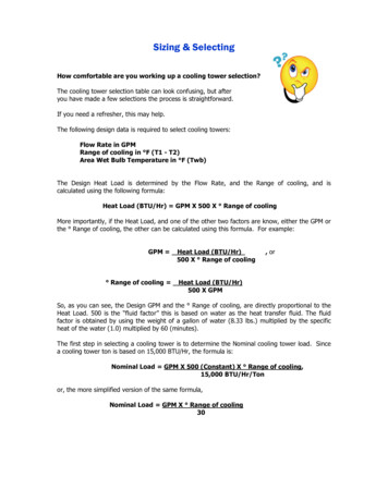
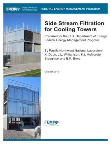
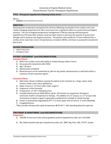
RETURN AIR TEMPERATUREThis furnace is designed for continuous return--air minimum temperature of 60 F (15 C) db or intermittent operation down to 55 F (13 C)db such as when used with a night setback thermometer. Return--air temperature must not exceed 80 F (27 C) db. Failure to follow thesereturn air limits may affect reliability of heat exchangers, motors and controls.80/ 27 C60/ 16 CSUPPLY AIRA10490MINIMUM CLEARANCES TO COMBUSTIBLE MATERIALSPOSITIONRearFront (Combustion air openings in furnace and in structure)Required for serviceAll Sides of Supply PlenumSidesVentTop of FurnaceCLEARANCE0 (0 mm)1 in. (25 mm)*24 in. (610 mm)1 in. (25 mm)0 (0 mm)0 (0 mm)1 in. (25 mm)* RecommendedVENTILATED COMBUSTION--AIR PIPE FOR ATTIC/CRAWLSPACE APPLICATIONSFIELD-SUPPLIED2-IN. (51 mm) DIA.TIGHT RADIUSPVC 90 ELBOWFIELD-SUPPLIED2-IN. (51 mm) DIA.PVC PIPE12” (300 mm) MinimumA11487NOTE: See Installation Instructions for specific venting configurations.10
DOWNFLOW SUBBASELOCATINGTAB1 1/4" dDisassembledDIMENSIONS (IN. / MM)PLENUM OPENING*FLOOR OPENINGHOLE NO. FORWIDTHADJUSTMENTFURNACECASING WIDTHFURNACE IN DOWNFLOWAPPLICATIONBCD17--- 1/2 (444.5)Furnace with or without Cased CoilAssembly or Coil Box15--- 1/8(384.2)19 (482.6)16--- 3/4(425.5)20--- 3/8(517.5)321 (533.4)Furnace with or without Cased CoilAssembly or Coil Box18--- 5/8(396.4)19 (482.6)20--- 1/4(514.4)20--- 3/8(517.5)224--- 1/2 (622.3)Furnace with or without Cased CoilAssembly or Coil Box22--- 1/8(562.0)19 (482.6)23--- 3/4(603.3)20--- 3/8(517.5)1A*The plenum should be constructed 1/4 ---in. (6 mm) smaller in width and depth than the plenum dimensions shown above.Concentric Vent KitDownflow SubbaseA93086A concentric vent kit allows vent and combustion--air pipes toterminate through a single exit in a roof or side wall. One piperuns inside the other allowing venting through the inner pipe andcombustion air to be drawn in through the outer pipe.A88202One base fits all furnace sizes. The base is designed to be installedbetween the furnace and a combustible floor when no coil box isused or when a coil box other than a Carrier cased coil is used. It isCSA design certified for use with Carrier branded furnaces wheninstalled in downflow applications.11
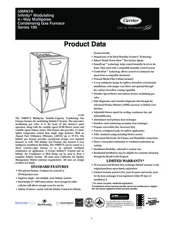
MEDIA FILTER CABINET25-5/8"(651mm)24-1/4”(616mm)Opening with Flanges (594mm)B OpeningADuct SideFurnace Side23-3/4”(603mm)Centerline Screw Slots5 3 4"(146mm)A11456ADIMENSIONS (IN. / MM)MEDIA FILTER CABINETABSHIPPED WITH SIZES16 (406.4)17 (432.8)16 (406.4)040--- 08, 040--- 12, 060--- 08,060--- 12, 080--- 12, 080--- 1620 (508.0)21 (533.4)20 (508)080--- 20, 100--- 16, 100--- 2024 (609.6)25 (635.0)24 (609.6)120--- 20, 140--- 20TYPICAL WIRING SCHEMATICFIELD 24-VOLT WIRINGFIELD 115-, 208/230-, 460-VOLT WIRINGFACTORY 24-VOLT WIRINGFACTORY 115-VOLT WIRINGNOTE MINALSFIELD-SUPPLIEDFUSED VOLT FIELD- JUNCTIONSUPPLIEDBOXFUSEDDISCONNECTCONTROL208/230- OR460-VOLTTHREEPHASEW2COMW/W1Y/Y2NOTE /230VOLTSINGLEPHASENOTES: 1. Connect Y/Y2-terminal as shown for proper operation.2. Some thermostats require a "C" terminal connection as shown.3. If any of the original wire, as supplied, must be replaced, usesame type or equivalent wire.A1140112
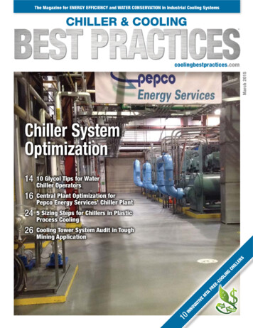
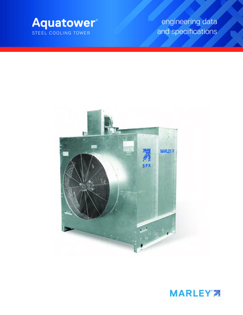
131[25.4]7/8[22.2]21[534.0]26 5/16[668.8]22[558.3]SIDE INLET7/8[22.2]7/8[22.2]THERMOSTAT ENTRYCONDENSATE DRAIN TRAPLOCATIONAIR FLOW19 1/8[485.8]17 5/16[439.2]20 1/4[513.9]14 13/16[376.3]16 9/16[420.9]28 3/16[715.9]25 3/16[639.1]22 15/16[581.9]5/8[15.8]28 5/8[726.4]11/16[17.5]32 5/8[829.5]CBOTTOM RETURNWIDTHAIR FLOW35[889.0] 30 7/16[773.7]28 3/8[720.4]3[76.2]AIR INTAKE11/16[17.5]28 5/8[726.9]16 9/16[420.9]17 7/16[442.3]20 1/4[513.9]24[609.7]3[76.2 ]1 5/16[33.3]7/8[22.2]26 5/16[668.8]23 3/8[592.0]SIDE INLET7/8[22.2]7/8[22.2]THERMOSTAT ENTRY7/8[22.2] POWER CONN1 3/4[44.5]GAS CONN7/8[22.2]AIR FLOW21 1/16[535.8]d. For airflow requirements above 1800 CFM, see Air Delivery table in these installation instructions for specific use of single side inlets. The use of both side inlets, a combinationof 1 side and the bottom, or the bottom only return air openings may be required for airflow requirements above 1800 CFM at 0.5 in. W.C. E.S.P.c. For 1600 CFM--- 22--- in. (559 mm) round or 14 1/2 x 22 1/16--- in. (368 x 560mm) rectangle.b. For 1200 CFM--- 20--- in. (508 mm) round or 14 1/2 x 19 1/2--- in. (368 x 495 mm) rectangle.a. For 800 CFM--- 16--- in. (406 mm) round or 14 1/2 x 12--- in. (368 x 305 mm) rectangle.NOTE: Doors may vary by model.7/8[22.2]7/8[22.2] POWER CONN3[76.2]VENT1 3/4[44.5]GAS CONNBOUTLET WIDTH22 7/16[670.0]26 3/8[370.0]A28 3/4[730.5]29 1/2[749.3]23 5/16[592.9]D26 11/16[678.1]3[76.2]AIR INTAKE3[76.2]AIR INTAKE3[76.2]VENT2 3/10[58.4]25 1/8[638.7]26 3/8[670.0]26 11/16[678.1]6 11/16[170.1]6 15/16[176.1]SD5024-4NONENEXT SHEETPART NUMBER1[25.4]DIMENSIONAL DRAWINGA11518
GUIDE SPECIFICATIONSGeneralSystem DescriptionFurnish a 4--way multipoise gas--firedcondensing furnace for use with natural gas or propane (factory-authorized conversion kit required for propane); furnish cold airreturn plenum; furnish external media cabinet for use withaccessory media filter or standard filter.Quality AssuranceUnit will be designed, tested and constructed to the current ANSI Z21.47/CSA 2.3 design standard for gas--fired central furnaces.Unit will be third party certified by CSA to the current ANSI Z21.47/CSA 2.3 design standard for gas--fired central furnaces. Unitwill carry the CSA Blue StarR and Blue FlameRlabels. Unitefficiency testing will be performed per the current DOE testprocedure as listed in the Federal Register.Unit will be certified for capacity and efficiency and listed in thelatest AHRI Consumer’s Directory of Certified Efficiency Ratings.Unit will carry the current Federal Trade Commission EnergyGuide efficiency label.Delivery, Storage, and HandlingUnit will be shipped as single package only and is stored andhandled per unit manufacturer’s recommendations.Warranty (for inclusion by specifying engineer)U.S. and Canada only. Warranty certificate available upon request.EquipmentBlower Wheel and ECM Blower MotorGalvanized blower wheel shall be centrifugal type, statically anddynamically balanced. Blower motor of ECM type shall bepermanently lubricated with sealed ball bearings, of hp,and have infinitely variable speed from 300--1300 RPM operatingonly when 24--VAC motor inputs are provided. Blower motor shallbe direct drive and soft mounted to the blower scroll to reducevibration transmission.FiltersFurnace shall have reusable--type filters. Filter shall be in.(mm) X in. (mm). An accessory highly efficient MediaFilter is available as an option. Media Filter.CasingCasing shall be of .030 in. thickness minimum, pre--paintedgalvanized steel.Draft Inducer MotorDraft inducer motor shall be variable--speed design.Copyright 2011 Carrier Corp. S 7310 W. Morris St. S Indianapolis, IN 46231Printed in U.S.A.Primary Heat ExchangersPrimary heat exchangers shall be 3--Pass corrosion-- resistantaluminized steel of fold--and--crimp sectional design and appliedoperating under negative pressure.Secondary Heat ExchangersSecondary heat exchangers shall be of a stainless steelflow--through of fin--and--tube design and applied operating undernegative pressure.ControlsControls shall include a micro--processor--based integratedelectronic control board with at least 16 service troubleshootingcodes displayed via diagnostic flashing LED light on the control, aself--test feature that checks all major functions of the furnace, anda replaceable automotive--type circuit protection fuse. Multipleoperational settings available, including separate blower speeds forall modulating heating capacities, low cooling, high cooling andcontinuous fan. Continuous fan speed may be adjusted from thethermostat. Cooling airflow will be selectable between 325 and400 CFM per ton of air conditioning. Features will also includetemporary reduced airflow in the cooling mode for improveddehumidification when an Infinity Control or TP--PRH edgeR isselected as the thermostat.Operating CharacteristicsHeating capacity shall be Btuh input;Btuh output capacity.Fuel Gas Efficiency shall be AFUE.Air delivery shall be cfm minimum at 0.50 in.W.C. external static pressure.Dimensions shall be: depth in. (mm); widthin. (mm); height in. (mm) (casing only).Height shall be in. (mm) with A/C coil andin. (mm) overa
inside door figure). furnace control board manual reset rollout switch flame sensor manual reset rollout switch gas burner hot surface igniter inducer motor assembly blower and motor capacitor/ power choke (if used) blower door safety switch a11408. 4 accessories description part number 060-1