Transcription
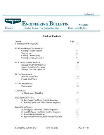
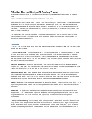
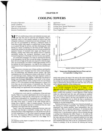
CHAPTER 39COOLING TOWERSwPrinciple of Operation .39.1Design Conditions . 39.2Types of Cooling Towers .39.2Materials of Construction . 39.7Selection Considerations . 39.7Application .Performance Curves .Cooling Tower Thermal Pevformance .Cooling Tower Theory.Tower Coeficients .39.739.1339.1539.1539.17MOST air-conditioning systems and industrial processes generate heat that must be removed and dissipated. Water iscommonly used as a heat transfer medium to.remove heat fromrefrigerant condensers or industrial process heat exchangers. In thepast, this was accomplished by drawing a continuous stream ofwater from a utility water supply or a natural body of water, heatingit as it passed through the process, and then discharging the waterdirectly to a sewer or returning it to the body of water. Water purchased from utilities for this purpose has now become prohibitivelyexpensive because of increased water supply and disposal costs.Similarly, cooling water drawn from natural sources is relativelyunavailable because the ecological disturbance caused by theincreased temperature of discharge water has become unacceptable.Air-cooled heat exchangers cool water by rejecting heat directlyto the atmosphere, but the first cost and fan energy consumption ofthese devices are high and the plan area required is relatively large.They can economically cool water to within approximately 20 F ofthe ambient dry-bulb temperature-too high for the cooling waterrequirements of most refrigeration systems and many industrial processes.Cooling towers overcome most of these problems and thereforeare commonly used to dissipate heat from water-cooled refrigeration, air-conditioning, and industrial process systems. The waterconsumption rate of a cooling tower system is only about 5% of thatof a once-through system, making it the least expensive system tooperate with purchased water supplies. Additionally, the amount ofheated water discharged (blowdown) is very small, so the ecological effect is greatly reduced. Lastly, cooling towers can cool water towithin 4 to 5 F of the ambient wet-bulb temperature, or about 35 Flower than can air-cooled systems of reasonable size. This lowertemperature improves the efficiency of the overall system, therebyreducing energy use significantly and increasing process output.PRINCIPLE OF OPERATIONA cooling tower cools water by a combination of heat and masstransfer. Water to be cooled is distributed in the tower by spray nozzles, splash bars, or film-type fill, which exposes a very large watersurface area to atmospheric air. Atmospheric air is circulated by (1)fans, (2) convective currents, (3) natural wind currents, or (4) induction effect from sprays. A portion of the water absorbs heat tochange from a liquid to a vapor at constant pressure. This heat ofvaporization at atmospheric pressure is transferred from the waterremaining in the liquid state into the airstream.Figure 1 shows the temperature relationship between water andair as they pass through a counterflow cooling tower. The curvesindicate the drop in water temperature (A to B) and the rise in the airwet-bulb temperature (C to D) in their respective passages throughthe tower. The temperature difference between the water enteringand leaving the cooling tower (A minus B) is the range. For a'PERCENT DISTANCETHROUGH TOWERFig. 1 Temperature Relationship Between Water and Airin Counterflow Cooling Towersteady-state system, the range is the same as the water temperaturerise through the load heat exchanger,provided the flow rate throughthe cooling tower and heat exchanger are the same. Accordingly, therange is determined by the heat load and water flow rate, not by thesize or thermal capability of the cooling tower.The difference between the leaving water temperature and entering air wet-bulb temperature (B minus C) in Figure 1 is theapproach to the wet bulb or simply the approach of the coolingtower. The approach is a fimction of cooling tower capability, and alarger cooling tower produces a closer approach (colder leavingwater) for a given heat load, flow rate, and entering air condition.Thus, the amount of heat transferred to the atmosphere by the cooling tower is always equal to the heat load imposed on the tower,whereas the temperature level at which the heat is transferred isdetermined by the thermal capability of the cooling tower and theentering air wet-bulb temperature.Thermal performance of a cooling tower depends principally onthe entering air wet-bulb temperature. The entering air dry-bulbtemperature and relative humidity, talcen independently, have aninsignificanteffect on thermal verformance of mechanical-draft"cooling towers, but do affect the rate of water evaporation in thecooling tower. A psychromehic analysis of the air passing througha cooling tower illustrates this effect (Figure 2). Air enters at theambient condition Point A, absorbs heat and mass (moisture) fromthe water. and exits at Point B in a saturated condition (at verv light"loads, the discharge air may not be fully saturated). The amount ofheat transferred from the water to the air is proportional to the difference in enthalpy of the air between the entering and leavingdThe preparation of this chapter is assigned to TC 8.6, Coollng Towers andEvaporative Condensers.
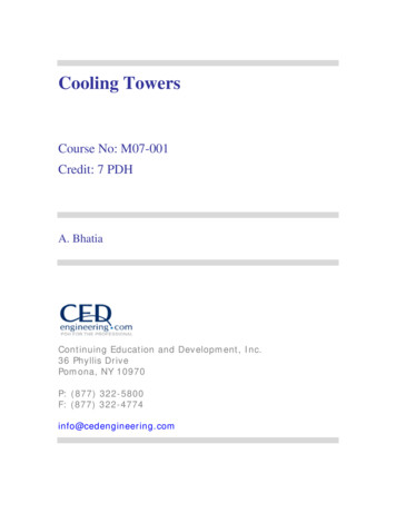
2008 ASHRAE Handbook-HVAC39.2conditions (hB- hA).Because lines of constant enthalpy correspondalmost exactly to lines of constant wet-bulb temperature, the changein enthalpy of the air may be determined by the change in wet-bulbtemperature of the air.Air heating (Vector AB in Figure 2) may be separated into component AC, which represents the sensible portion of the heatabsorbed by the air as the water is cooled, and component CB,which represents the latent portion. If the entering air condition ischanged to Point D at the same wet-bulb temperature but at a higherdry-bulb temperature, the total heat transfer (Vector DB) remainsthe same, but the sensible and latent components change dramatically. DE represents sensible cooling of air, while EB representslatent heating as water gives up heat and mass to the air. Thus, forthe same water-cooling load, the ratio of latent to sensible heattransfer can vary significantly.The ratio of latent to sensible heat is important in analyzingwaterusage of a cooling tower. Mass transfer (evaporation) occurs only inthe latent portion of heat transfer and is proportional to the changein specific humidity. Because the entering air dry-bulb temperatureor relative humidity affects the latent to sensible'heat transfer ratio,it also affects the rate of evaporation. In Figure 2, the rate of evaporation in Case AB (WB - WA)IS less than in Case DB (WB - WD)because the latent heat transfer (mass transfer) &presents a smallerportion of the total.The evaporation rate at typical design conditions is approximately1% of the water flow rate for each 12.5"F of water temperature range;however, the average evaporation rate over the operating season isless than the design rate because the sensible component of total heattransfer increases as entering air temperature decreases.In addition to water loss from evaporation, losses also occurbecause of liquid carryover into the discharge airstream and blowdown to maintain acceptable water quality. Both of these factors areaddressed later in this chapter.DESIGN CONDITIONSairflow though hyperbolic towers and directly establishes thermalcapability in any indirect-contact cooling tower component operating in a dry mode. Variations in tower performance associated withchanges in the remaining parameters are covered in the section onPerformance Curves.The thermal capability of a cooling tower used for air conditioning is often expressed in nominal cooling tower tons. A nominalcooling tower ton is defined as cooling 3 gpm of water from 95 F to85 F at a 78 F entering air wet-bulb temperature. At these conditions, the cooling tower rejects 15,000 Btuih per nominal coolingtower ton. The historical derivation of this 15,000 Btulh coolingtower ton, as compared to the 12,000 Btuih evaporator ton, is basedon the assumption-that at typical air-conditioning conditions, forevery 12,000 Btuih of heat picked up in the evaporator, the coolingtower must dissipate an additional 3000 Btuih of compressor heat.For specific applications,however, nominal tonnage ratings are notused, and the thermal performance capability of the tower is usuallyexpressed as a water flow rate at specific operating temperature conditions (entering water temperature, leaving water temperature,entering air wet-bulb temperature).TYPES OF COOLING TOWERSTwo basic types of evaporative cooling devices are used. The firstof these, the direct-contact or open cooling tower (Figure 3), exposes water directly to the cooling atmosphere, thereby transferringthe source heat load directly to the air. The second type, often calleda closed-circuit cooling tower, involves indirect contact betweenheated fluid and atmosphere (Figure 4), essentially combining a heatexchanger and cooling tower into one relatively compact device.Of the direct-contact devices, the most rudimentary is a sprayfilled tower that exposes water to the air without any heat transfermedium or fill. In this device, the amount of water surface exposed tothe air depends on the spray efficiency, and the time of contact depends on the elevation aid pressure ofthe water distribution system.The thermal capability of any cooling tower may be defined bythe following parameters:HEATED AND HUMIDIFIEDAIR OUTtEntering and leaving water temperaturesEntering air wet-bulb or entering air- wet-bulb and dry-bulbtemperaturesWater flow rateThe entering air dry-bulb temperature affects the amount ofwater evaporated from any evaporative cooling tower. It also affectsSystems and Equipment-DRIFTDISTRIBUTIONELIMINATORSPHOT WATERLEAVINGWET-BULBTEMPERATUREISENSIBLE HEATTRANSFERIDRY-BULB TEMPERATUREFig. 2 Psychrometric Analysis of Air Passing ThroughCooling Tower,COLD WATER TO PUMPPFig. 3 Direct-Contact or Open Evaporative Cooling Tower
Cooling TowersTOincrease contact surfaces as well as time of exposure, a heattransfer medium, or fill, is installed below the water distributionsystem, in the path of the air. The two types of fill in use are splashtype and film-type (Figure 5). Splash-type fill maximizes contactarea and time by forcing the water to cascade through successiveelevations of splash bars arranged in staggered rows. Film-type fillachieves the same effect by causing the water to flow in a thin layerover closely spaced sheets, principally polyvinyl chloride (PVC),that are arranged vertically.HEATED AND HUMIDIFIEDAIR OUT\p7DRIFT ELIMINATORSsDISTRIBUTIONwATyEither type of fill can be used in counterflowand cross-flow towers. For thermal performance levels typically encountered in airconditioning and refrigeration, a tower with film-type fill is usuallymore compact. However, splash-type fill is less sensitive to initialair and water distribution and, along with specially configured,more widely spaced film-type fills, is preferred for applicationsthatmay be subjected to blockage by scale, silt, or biological fouling.Indirect-contact (closed-circuit) cooling towers contain twoseparate fluid circuits: (1) an external circuit, in which water isexposed to the atmosphere as it cascades over the tubes of a coilbundle, and (2) an internal circuit, in which the fluid to be cooledcirculates inside the tubes of the coil bundle. In operation, heatflows from the internal fluid circuit, through the tube walls of thecoil, to the external water circuit and then, by heat and mass transfer, to atmospheric air. As the internal fluid circuit never contactsthe atmosphere, this unit can be used to cool fluids other thanwater and/or to prevent contamination of the primary cooling circuit with airborne dirt and impurities. Some closed-circuit cooling tower designs include cooling tower fill to augment heatexchange in the coil (Figure 6).Types of Direct-Contact Cooling TowersCLOSED-CIRCUITHEAT EXCHANGECOILCLOSEDCIRCUITFig. 4 Indirect-Contact or Closed-CircuitEvaporativeCooling TowerFILM-TYPE FlLL PACKINGNon-Mechanical-Draft Towers. Aspirated by sprays or a differential in air density, these towers do not contain fill and do not usea mechanical air-moving device. The aspirating effect of the waterspray, either vertical (Figure 7) or horizontal (Figure 8), induces airflow through the tower in a parallel flow pattern.Because air velocities for the vertical spray tower (both entering and leaving) are relatively low, such towers are susceptible toadverse wind effects and, therefore, are normally used to satisfy alow-cost requirement when operating temperatures are not criticalto the system. Some horizontal spray towers (Fi,aure 8) use highpressure sprays to induce large air quantities and improve airlwatercontact. Multispeed br staged pumping systems are normally recommended to reduce energy use in periods of reduced load andambient conditions.Chimney (hyperbolic) towers have been used primarily for largepower installations, but may be of generic interest (Figure 9). Theheat transfer mode may be counterflow, cross-flow, or parallel flow.Air is induced through the tower by the air density differentials thatexist between the lighter, heat-humidified chimney air and the outsideatmosphere. Fill can be splash or film type.Primary justification of these high firs
Cooling Tower Fig. 3 Direct-Contact or Open Evaporative Cooling Tower . Cooling Towers TO increase contact surfaces as well as time of exposure, a heat transfer medium, or fill, is installed below the water distribution system, in the path of the air. The two types of fill in use are splash- type and film-type (Figure 5). Splash-type fill maximizes contact area and time by forcing the water to .