Transcription
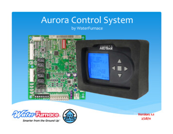
Instruction Guide:INSTRUCTION GUIDE: AID TOOLAurora Interface and Diagnostics (AID) ToolTable of ContentsGeneral, Menu Diagram. . . . . . . . . . . . . . . . . .Startup, Communication Failure/Error, ABC Overview . .Main Menu, System Faults . . . . . . . . . . . . . . . .Lockout Details, Fault History, Clear Fault Counters,Diagnostics. . . . . . . . . . . . . . . . . . . . . .Thermostat Inputs, Thermostat Override, ThermostatOverridden, DIP Switch Settings . . . . . . . . . . .Clear DIP Switch Override, Sensor Inputs, System OutputsTimers, Refrigerant Monitoring, Energy Monitoring,Performance Monitoring, AXB Inputs, AXB Outputs .Setup, ECM Setup, ECM Speed Setup . . . . . . . . . .Cooling Airflow Setup, AXB Setup, Sensor Kit Setup . . .Smart Grid Setup, Home Automation Setup, ConfigureAurora System . . . . . . . . . . . . . . . . . . . .About Unit, Rewiring Instructions, AID Settings, VariableSpeed Overview, System Faults/Variable SpeedDrive Details . . . . . . . . . . . . . . . . . . . . .System Faults, Diagnostics/Variable Speed ManualOperation, Variable Speed Sensors and Ref . . . . .1. .2. .3. .4. .5. .6. .7. .8. .9. 10. 11Menu Diagram - Aurora Advanced Control(ABCSTD Version 2.xx). 12GeneralMain MenuThe Aurora Interface and Diagnostics (AID) Tool is a devicethat is a member of the Aurora network. The AID Tool is used totroubleshoot equipment which use the Aurora control via ModbusRTU communication. The AID Tool provides diagnostics, faultmanagement, ECM setup, and system configuration capabilitiesto the Aurora family. The AID Tool has a 2-1/2 in. x 2-1/2 in. LCDdisplay and five push buttons. The up, down, right and left buttonswill be referenced as , , and , respectively. The centerbutton is the enter button and will be referenced as .ABC OverviewThermostat InputsSystem FaultsLast LockoutDIPSwitch SettingsFault HistorySensor InputsDiagnosticsSystem OutputsSetupECM Speed Setup V2TimersNote: 2Config AuroraSystem V2Menu Diagram - Aurora Base Control(ABCSTD Version 1.xx)Cooling AirflowSetupRefrig MonitorNote: 1About UnitLine Voltage SetupEnergy MonitorNote: 2Main MenuAXB SetupPerformanceMonitorThermostat InputsSensor Kit SetupAXB InputsLast LockoutDIPSwitch SettingsSmart Grid SetupAXB OutputsFault HistorySensor InputsHome AutomationSetupSystem OutputsPower AdjustmentFactorTimersUpdate ModelNumberABC OverviewSystem FaultsNote: 3DiagnosticsSetupECM Speed SetupConfig AuroraSystemUpdate ModelNumberAbout UnitUpdate SerialNumberUpdate SerialNumberAID SettingsContrastAID SettingsMixed Case TextContrastUnitsMixed Case TextNote 1 - Available only when the AXB is NOT installed.Note 2 - Available only when the AXB is installed.Note 3 - Available on ABCSTD version 2.04 with an AXB installed.Units*IG1563EW*IG1563EW 11/141
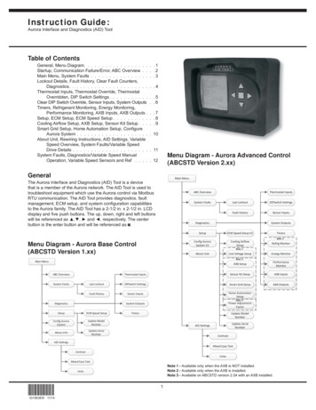
INSTRUCTION GUIDE: AID TOOLMenu Diagram - Aurora Advanced Controlfor Variable Speed (ABCVSP Version 2.xx)Communication Failure/ErrorIn the event of a communicationfailure or error, this screen willappear. One of the following willbe displayed: READ ERRORNO RESPONSE, READERROR CRC, READ ERROREXCEPTION, WRITE ERRORNO RESPONSE, or WRITEERROR EXCEPTIONMain MenuABC OverviewVS Drive DetailsVS ManualOperationSystem FaultsLast LockoutDIPSwitch SettingsFault HistorySensor InputsDiagnosticsECM Speed Setup V2TimersConfig AuroraSystem V2Cooling AirflowSetupVS ServiceThe communication cable andReturn to Main MenuEnter Demo Modeconnection should be checkedto make sure a solid connectionhas been made with the ABCand that the cable connectingthe AID Tool and ABC is notdamaged. To retry to connect to the ABC, highlight the RETRYTO CONNECT using the and buttons and then press the button to select the option or return to the Main Menu.Note: 1About UnitLine Voltage SetupVS Sensors and RefNote: 2AXB SetupEnergy MonitorSensor Kit SetupPerformanceMonitorSmart Grid SetupAXB InputsHome AutomationSetupAXB OutputsError:Communication FailedRead ErrorNo ResponseAuroraRetry To ConnectSystem OutputsSetupAuto Retry in XNote: 2Demo mode is also available. Demo mode will allow the technicianto navigate through the AID Tool without being connected to anABC control. Once demo mode has been entered, power must beremoved from the AID Tool to restart communication.Note: 3Power AdjustmentFactorUpdate ModelNumberThe AID Tool will automatically retry communication in 30 secondsafter the fault.Update SerialNumberAID SettingsContrastABC OverviewThe ABC Overview screenprovides the ABC control status,fault status, current mode ofoperation, DIP configurationmode, and DIP setting. You cango to the Main Menu by pressingthe button. Test Mode can beenabled or disabled by pressingthe button.Mixed Case TextUnitsNote 1 - Available only when the AXB is NOT installed.Note 2 - Available only when the AXB is installed.Note 3 - Available on ABCVSP version 2.04 with an AXB installed.StartupWhen the AID Tool is pluggedinto the AID Tool port on thefront corner post or directly toP8 on the Aurora Base Control(ABC), a flash screen willappear for 5 seconds.The tool will then initialize. Ifthe AID Tool’s software versionis older than what the ABCrequires, an ‘Attention’ screenwill appear, otherwise the ABCOverview screen will appear.Press the button to continueto the ABC Overview screen.NOTE: If the AID Tool’s softwareversion is older than what isrequired by the ABC, somefeatures may not be supportedby the AID on the ABC.*IG1563EW*IG1563EW 11/14Aurora InterfaceAnd Diagnostics-- AID Tool --Status - displays the currentcontroller status.NORMAL – Normal ModeTEST – Test ModeDEHUMID –Dehumidification ModeLOAD SHED – Load ShedE SHUTDOWN – Emergency ShutdownLOCKOUT - LockoutSoftwareVXX.XX--- Attention ---Faults - displays the current fault status.None – No FaultsRetry HP X – A high pressure fault has occurred, and the ABCis retrying. The X represents the number of times thisfault has occurred.Retry LP X – A low pressure fault has occurred, and the ABCis retrying. The X represents the number of times thisfault has occurred.Retry FP1 X – A freeze detection sensor number 1 fault hasoccurred, and the ABC is retrying. The X represents thenumber of times this fault has occurred.Retry FP2 X – A freeze detection sensor number 2 fault hasoccurred, and the ABC is retrying. The X represents thenumber of times this fault has occurred.A newer version ofthe AID software isavailable, pleaseupdate.Some features maynot be supported. Continue2
INSTRUCTION GUIDE: AID TOOLRetry Cond X – A condensate overflow fault has occurred,and the ABC is retrying. The X represents the number oftimes this fault has occurred.O/U Volt – An over/under voltage fault has occurred.Lock HP – A high pressure lockout has occurred.Lock LP – A low pressure lockout has occurred.Lock FP1 – A freeze detection sensor number 1 lockouthas occurred.Lock FP2 – A freeze detection sensor number 2 lockouthas occurred.Lock Cond – A condensate overflow lockout has occurred.Lock O/U Volt – An over/under voltage lockout has occurred.Lock Inputs – An inputs fault has occurred.Lock Sensor – A FP1 or FP2 sensor error has occurred.Main MenuThis screen allows thetechnician to select differentscreens to view information orchange settings. Change thehighlighted item using the and buttons and then pressthe button to select the item.Press the button to return tothe ABC Overview screen.ABC OVERVIEW – Providesa general overview of the ABCstatus and settings.System Faults – Providesthe ABC’s current fault andhistorical counts of faults.Mode - Displays the ABC’s current operation.Rdm Strt XXX – The random start delay is counting downbefore the ABC will begin normal operation.Waiting XXX – This displays the compressor short cycle timerwhen there is a demand for compressor operation.Standby – The ABC is idle and is waiting for athermostat input.Lockout – The ABC is currently locked out.Blower Only – The ABC is in blower only mode.Cooling – The ABC is in cooling mode and the stage isindicated by the number that follows.Heating – The ABC is in heating mode and the stage isindicated by the number that follows.Aux – This will be displayed in addition to the HEATING modeto indicate the auxiliary heat has been engaged.Dehum – The ABC is in dehumidification mode.Reheat – The ABC is in reheat mode.Emergency – The ABC has engaged the emergency heat outputs.IG1563EW 11/14Main MenuABC OverviewSystem FaultsDiagnosticsSetupConfig Aurora SystemAbout UnitAID SettingsOption Enter Diagnostics – Provides the ability to see the current thermostatinputs, outputs, DIP Switch settings and view sensor status andvalues. This also allows the technician to override the thermostatinputs for testing and clear a DIP Switch override.Setup – This allows the technician to set the variable speed ECMBlower Speed settings.Config Aurora System – Provides the ability to see what devicesare connected to the Aurora system. Software Version informationcan be found on this screen.About Unit – Allows the technician to view the ABC board’ssoftware version and program name, along with the unit’s modeland serial number.Conf - Displays the ECM and DIP Switch configuration setting.ECM X, X, X, X – This displays the “G”, Low, High, and AuxHeat variable speed ECM speed settings.Manual – The physical DIP Switches have NOT beenoverridden and control the configuration of the ABC.Overridden – The physical DIP Switches have beenoverridden and are not active.DIP Switch Settings – These are the current settings eitherphysically set on the ABC or overridden.FP1 –OFF 15 FON 30 FFP2 –OFF 15 FON 30 FRV –OFF BON OAR –OFF, OFF Cycle with CompressorON, ON Cycle with BlowerON, OFF Slow Opening Water ValveOFF, ON Cycle with T-stat Humidification Call(Communicating T-stat Only)CC –OFF Dual CapacityON Single CapacityLO –OFF Pulse OutputON Continuous OutputRH/DH – OFF Reheat EnabledON Dehumidification Enabled*IG1563EW* AID Settings – Allows adjustment of AID Tool screen contrast orupper to lower case text option.System FaultsThis screen shows thetechnician the current faultstatus of the ABC. Thetechnician can then view thefault details and also the faulthistory. Change the highlighteditem using the and buttons and then press the button to select the item. Pressthe button to return to theMain Menu.System FaultsStatus: LockoutFaults: HPS3Last LockoutFault HistoryStatus – displays the currentfault status of the ABC. BackNo Fault – No active faults.Retry – A fault hasoccurred and the ABC is attempting a retry.Lockout – The ABC is currently locked out.Fault – Displays the fault that has either caused a retry or alockout. (See the unit’s installation manual for fault details.)HPS – High Pressure Fault.LPS – Low Pressure FaultFP1 – Freeze Detection Sensor 1 FaultFP2 – Freeze Detection Sensor 2 Fault3
INSTRUCTION GUIDE: AID TOOLCondensate – Condensate Overflow FaultInput Faults – Input Fault (W thermostat input and Othermostat input were present at the same time.)O/U Volt SD – Over/Under Voltage Shutdown Fault (Thesupply voltage was too high or too low and the controllerwas shut down.)Sensor Error – Sensor Error Fault (The FP1 and FP2 sensorsshould be checked.Clear Fault CountersThis screen confirms that thefault counters are to be reset.Change the highlighted itemusing the and buttonsand then press the button toselect the item.Selecting YES will clearthe fault counters, whileselecting NO will return to theprevious screen.Lockout Details – Shows the inputs and outputs at the time of theactive or the last lockout.Fault History – Displays the number of faults that have occurredsince the controller has been cleared.Lockout DetailsLast Lockout: E2HPSThe diagnostics menu will allow the technician to view the currentthermostat inputs, override the thermostat inputs, view DIP Switchsettings, clear DIP Switch override, view the sensor inputs, viewthe active outputs, and view the timers. Change the highlighteditem using the and buttons and then press the button toselect the item. Press the button to return to the Main Menu.Active Inputs:Y1 G WDiagnosticsActive Outputs – The active ABC outputs at the time of the lockout.Thermostat InputsDIP Switch SettingsSensor InputsSystem OutputsTimersRefrig MonitorEnergy MonitorPerformance MonitorAXB InputsAXB Outputs BackOption BackOption Enter Diagnostics Fault HistoryCountInput FaultHigh PressureLow PressureFP 1FP 2CondensateO/U VoltageVS Manual OperationDIP Switch SettingsSensor InputsSystem OutputsTimersVS ServiceVS Sensors And RefEnergy MonitorPerformance MonitorAXB InputsAXB Outputs048025580Press to ClearFault History BackOption Enter BackABCVSP Version 2.xxwith AXB4DiagnosticsThermostat InputsDIP Switch SettingsSensor InputsSystem OutputsTimersABCSTD Version 1.xxFault HistoryIG1563EW 11/14Enter DiagnosticsActive Inputs – The active thermostat inputs at the time of the lockout.*IG1563EW*Clear Fault Counters?YesNoLockout DetailsLast Lockout – This showswhat fault caused a lockout.Active Outputs:HPS – High PressureCC G OFault.LPS – Low Pressure FaultFP1 – Freeze DetectionSensor 1 Fault BackFP2 – Freeze DetectionSensor 2 FaultCondensate – Condensate Overflow FaultInput Faults – Input Fault (W thermostat input and Othermostat input were present at the same time.)O/U Volt SD – Over/Under Voltage Shutdown Fault (Thesupply voltage was too high or too low and the controllerwas shut down.)Sensor Error – Sensor Error Fault (The FP1 and FP2 sensorsshould be checked).NOTE: There are multipleFault History pages forABCSTD Version 2.xx andABCVSP Version 2.xx.Please ConfirmSelection:Option This screen shows thetechnician the active or the lastlockout along with the inputsand outputs at the time of thelockout. Press the button toreturn to the previous screen.This screen displays thenumber of each fault that hasoccurred since the last time theABC was cleared. Press the button to return to the previousscreen. Press the button toclear the fault counters.WarningEnter ABCSTD Version 2.xxwith AXB
INSTRUCTION GUIDE: AID TOOLThermostat Inputs – View the current thermostat inputs and/oroverride the thermostat inputs.Thermostat OverrideThis screen will allow thetechnician to simulatethermostat inputs and overridethe current thermostat inputs.Change the highlighted itemusing the and buttons.Change the status by pressing and buttons. Press the button to complete the override.DIP Switch Settings – View the current DIP Switch settings andclear a DIP Switch override.Sensor Inputs – View the ABC sensor inputs.System Outputs – View the ABC’s active outputs.Timers – View the timers.NOTE: The ABC will return tonormal after 1 minute if the AIDTool is removed duringan override.Refrig Monitor – Allows the technician to monitor the pressures andtemperatures of the system. Refrigerant Monitoring Kit sensors mustbe installed. Standard on the variable speed product.Energy Monitoring – Allows the technician to monitor energy usefor the compressor, blower, and aux heat. The pump power isestimated based upon the configuration of the flow center. EnergyMonitoring Kit sensors must be installed. This option is standardon variable speed products.NOTE: The DH will bedisplayed as DH/RH if thereheat option is enabled.NOTE: DH Dehumidification Mode, RH Reheat ModePerformance Monitoring – Allows the technician to monitor heatof extraction and rejection performance of the heat pump thruentering and leaving water temps, water flow rate, and someselected air temperatures. Performance Monitoring Kit sensorsmust be installed.Thermostat OverriddenThis screen shows the activeoverride inputs. The overridecan be ended or updated.Change the highlighted itemusing the and buttons.Press the button to selectthe item.AXB Inputs – Allows the technician to monitor AXB inputs such ashot water sensor, pump slaving, home automation digital inputs,smart grid/On Peak input etc.AXB Outputs - Allows the technician to monitor AXB outputs such asLoop pump relay, HW pump relay, variable speed pump PWM etc.NOTE: The DH will bedisplayed as DH/RH if thereheat option is enabled.Thermostat InputsNOTE: DH DehumidificationMode, RH Reheat ModeThis screen allows thetechnician to view the currentthermostat inputs to the ABC.An active thermostat overridewill bypass this screen andshow the thermostat overriddenscreen. Change the highlighteditem using the and buttons and then press the button to select the item.Override w/ Different TstatSignals – Allows the technicianto continue to override the thermostat inputs, but change theselection. This screen will allow the technician to simulatethermostat inputs and override the current thermostat inputs.End Tstat Override – Return the thermostat to normal mode.Exit This Screen – Returns to the previous screen.NOTE: The DH will bedisplayed as DH/RH if thereheat option is enabled.NOTE: DH DehumidificationMode, RH Reheat ModeSelecting YES will start a thermostat override, while selecting NOwill return to the previous screen.NOTE: Communicating thermostats although do not have a 24VACconnection for Y1, Y2 etc. the display will show the equivalentcommunicating calls.*IG1563EW*IG1563EW 11/145
INSTRUCTION GUIDE: AID TOOLDIP Switch Settings Sensor InputsDIP Switch: ManualDIP Switch: OverriddenOn FP1 FP2 RV AR CC LO RHOn FP1 FP2 RV AR CC LO DH 15 F 15 F B Cycle WithCompressor Dual Stage Pulse Reheat OnThis screen displays theABC’s sensor inputs. Pressthe button to return to theprevious screen. 30 F 30 F O Cycle WithBlower Single Stage Continuous Dehum OnNOTE: If FP2 is not installed a“—“ will be displayed in placeof the temperature.FP1 – Freeze DetectionSensor 1 FaultFP2 – Freeze DetectionSensor 2 FaultHPS – High Pressure SwitchStatus – Open/ClosedLPS – Low Pressure SwitchStatus – Open/ClosedCondensate – Condensate Overflow Status – Fault/NormalEmergency Shutdown – Emergency Shutdown Status – On/OffLoad Shed – Load Shed Status – On/OffFault – Displays the fault that has either caused a retry or alockout. (See the unit’s installation manual for fault details.)Press To ClearOverride Back BackThis screen allows the technician to view the DIP switch settingsand determine if the physical DIP switches have been overridden.The technician can clear the override if the DIP switches havebeen overridden. Press the button to return to the previousscreen. If the DIP switches have been overridden, press the button to clear the override.DIP Switch Settings – These are the current settings on the ABC.FP1 –OFF 15 FON 30 FFP2 –OFF 15 FON 30 FRV –OFF BON OAR –OFF, OFF Cycle with compressorON, ON Cycle with BlowerON, OFF Slow Opening Water ValveOFF, ON Cycle with T-stat Humidification Call(Communicating T-stat Only)CC –OFF Dual CapacityON Single CapacityLO –OFF Pulse OutputON Continuous OutputRH/DH – OFF Reheat EnabledON Dehumidification EnabledSystem OutputsThis screen displays theABC’s current outputs. Pressthe button to return to theprevious screen.Clear DIP Switch OverrideSelecting YES will clear theDIP switch override, whileselecting NO will return to theprevious screen. WarningPlease Confirm Selection:Clear DIP SwitchOverride?Yes NoOption *IG1563EW*IG1563EW 11/14System 1:EH2:ECM:5-Spd ECM:OnOnOffOnOffOffOffOnOn0 - OffOffRV – Reversing Valve – On/OffCC – Compressor Low Capacity– On/OffCC2 – Compressor HighCapacity – On/OffBlower – Blower Relay – On/OffAlarm – Alarm Output – On/OffNOTE: This will be Backreplaced by Reheat ifreheat is enabled.Accessory – Accessory Relay – On/OffLockout – Lockout – On/OffEH1 – Electric Heat Stage 1 – On/OffEH2 – Electric Heat Stage 2 – On/OffECM Speed - Displays the variable speed ECM blower speed Off,Low (G or Fan), Med (Y1), High (Y2), Aux (W).5-Spd ECM Speed - Displays the 5-Speed ECM blower speed Off,Low (G or Fan), Med (Y1 or CC), High (Y2 or CC2), Aux (Wor EH1).If the DIP switches have been overridden and you wish to clearthem, see the Clear DIP
that is a member of the Aurora network. The AID Tool is used to troubleshoot equipment which use the Aurora control via Modbus RTU communication. The AID Tool provides diagnostics, fault management, ECM setup, and system configuration capabilities to the Aurora family. The AID Tool has a 2-1/2 in. x 2-1/2 in. LCD display and five push buttons.File Size: 1MB