Transcription
Aurora Control Systemyby WaterFurnace
Aurora Base Control Board Provide basic safety shutdown, faultindication, and time delays Provide control for ECM and Dualcapacity unit Provide Hot Gas Reheat Control onsingle stage compressor units DIP switches for field selection ofminimum configurations Fault/Status/Configuration LEDs foruse without AID Tool2
Aurora Interface Diagnosticg(AID)() Tool Low Cost Service Tool RJ45 ‘EthernetEthernet stylestyle’ connectionto ABC Hardware based uponp thermostat Modbus interface with AuroraControl System3
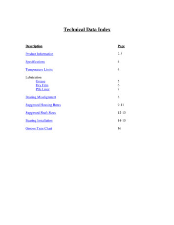
Aurora Control ‐ Ultra PSC ControlPSC Fan motorThermostatNote: Fault via FlashingLED’s and configurationvia DIP switchesSingle SpeedAurora Base Control
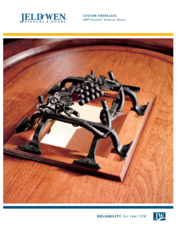
Aurora Control ‐ Ultra ECM ControlECM Fan motorThermostatPWMDual or Single ScrollAurora Base ControlAID ToolNote: Fault and configuration via Flashing LED’s, DIPswitches or AID tool
Aurora Board
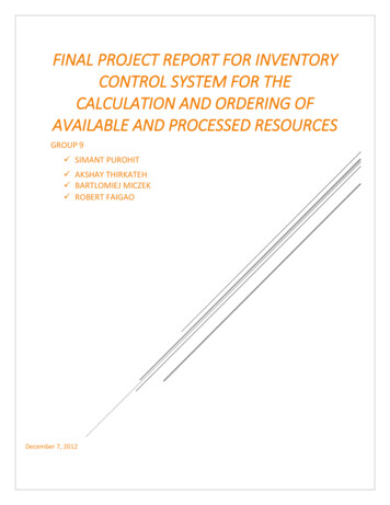
SW1 DetailsSW1Test Mode Button &ECM ConfigurationC fiti
SW1 DetailsHolding SW1Description ofOperationLED2 seconds to 5 secondsEnter test modeGreen LED slow flash5 seconds to 10 secondsEnter ECM configuremodeYellow LED fast flash50 seconds to 60 secondsReset configure modeGreen LED offLonger than 60 secondsSW1 operation cancelYellow LED back tonormal Automatically reverts to Normal Mode after 30 minutes.
SW1 Test Mode The control is placed in the Test Mode by holding the pushbuttonswitchit h SW1 forf 2 - 5 seconds.d In the Test Mode most of the control timings will be shortened by afactor of sixteen (16), with exception of fault recognition times. The GREEN LED will flash: 1 second on / 1 second off. When entering the Test Mode, the RED LED will flash the last lockoutfailure code one time. Test Mode will automatically time out after 30 minutes.
SW1 Test ModeRed Fault LEDGreen Status LEDYellow Configuration LED
SW2 DetailsSW2Dip Switch 2-1 thru 2-8
SW2 DetailsSW2Dip Switch 2-1 thru 2-8
SW2 DetailsSW2-1 Freeze Protection: Dip SW 2-1On 30 FOff 15 FSW2-2 (Future Use - Disabled in Ver 1.0)SW2-3 Reversing Valve LogicOn “O” RV Energized for Cooling ModeOff “B”B RV Energized for Heating Mode
SW2 DetailsSW2-4 and SW2-5 Accessory Relay ConfigurationRelay FunctionSW2-4 SW2-5Cycle with FanOnOnCycle with CompressorOffOffSlow Opening Water ValveOnOff(Also Cycles with Compressor)Reserved for Future UseOffOn
SW2 DetailsSW2-6 Compressor ConfigurationSW2-6On Single Capacity CompressorOff Dual Capacity Scroll Compressor
SW2 DetailsSW2-7 Lockout Signal and Alarm Relay OutputSW2-7On Fault Signal “LO” on t/stat terminal block is continuousand the Alarm Relay Contacts close on any FaultOff Fault Signal “LO” on t/stat terminal block Pulses On and Offand the Alarm Relay Contacts Opens & Closes duplicatingthe Fault LED Blinking Pattern
SW2 DetailsSW2-8 Hot Gas ReheatSW2-8On Standard UnitOff Hot Gas Reheat EnabledWhen Hot Gas Reheat is enabled, the Alarm Relay is used toenergize the hot gas reheat valve. So when the hot gas reheatoption is orderedordered, no alarm relay output is availableavailable.
Alarm JumperJW2JW224Vac or Dry ContactF lt OutputFaultO t t
Alarm JumperJW2JW224Vac or Dry ContactF lt OutputFaultO t t
Alarm JumperJW2JW224Vac or Dry Contact Fault OutputFactoryy setting:g JW2 Jumperp Wire IntactFault Alarm Relay output is connected to 24VACClipping the JW2 Jumper Wire:Fault Alarm Relay Contacts will be a dry contact output
by WaterFurnace. Aurora Base Control Board Provide basic safety shutdown, fault indication, and time delays Provide control for ECM and Dual capacity unit . use without AID Tool 2. Aurora Interface Diagnostic (()AID)