Transcription
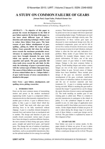
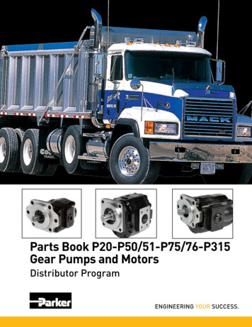
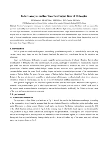
CHAPTER 14GEARS AND GEAR CUTTINGCHAPTER LEARNING OBJECTIVESUpon completing this chapter, you should be able to do the following:Describe the materials used to manufacture gears.Explain the manufacture of gears, splines, and sprockets.Explain the process used to set up gear trains.If not, you may have to find the specifications orblueprints for the original gear. In some cases youshould consult a machinist’s handbook, whichprescribes various materials. Do this to be sure thematerial you are using will hold up under the stressesthe gear will encounter.This chapter covers the manufacture of spur gears,helical gears, bevel gears, stub tooth gears, worms,worm gears, splines, and sprockets.Gears have always been a highly essential elementin machinery used aboard ships and at naval shorefacilities. In today’s Navy, the emphasis on speed,power, and compactness in naval machinery has createdspecial problems for the machinist cutting a gear.Today’s machinists must be able to turn out a noiseless,practically unbreakable gear that transmits largeamounts of power in small spaces. This requires greatskill and precision.Gears are made from ferrous, nonferrous, andnonmetallic materials. Steel, for example, is usedwhenever great strength and toughness are required.Nonferrous metals such as bronze and brass are oftenused aboard naval ships for gears that must resistsaltwater corrosion.Monel and aluminum may be used for gears, wherecorrosion resistance is of primary importance. Nonmetallic gearing is frequently used where quietoperation is important. Nonmetallic gears are mosteffective at high-speeds. However, they do not alwayshold up against the wide fluctuations of load and thehigh shock loads encountered at low speeds. Gearsmade of nonmetallic materials have a lower tensilestrength than those constructed of metallic materials,but their greater resiliency gives them approximatelythe same power-transmitting capacity as cast iron.This chapter will cover gear cutting practices on astandard milling machine. If you encounter problemswhen you calculate or cut gears, consult a machinist’shandbook for more detailed information.As with any shop equipment you must observe allposted safety precautions. Review your equipmentoperators manual for safety precautions. Also read anychapters of Navy Occupational Safety and Health(NAVOSH) Program Manual for Forces Afloat,OPNAV Instruction 5100.19B, that apply to theequipment.MATERIALS USED FOR GEARSSPUR GEARSThe choice of material for a particular gear isusually based on the function of the gear. This involvesfactors such as the speed of operation, the type of stress,the importance of quiet operation, and the need forresistance to corrosion. The easiest way to determinewhat material to use for a replacement gear is to find outwhat material was used for the gear you must replace.In most cases, you will have the original gear to go by.A gear is made by cutting a series of equally spaced,specially shaped grooves on the periphery of a wheel(see fig. 14-1).To calculate the dimensions of a spur gear, youmust know the parts of the gear. You also must knowthe formulas for finding the dimensions of the parts. Tocut the gear you must know what cutter to use and how14-1
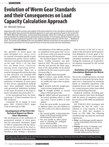
PITCH CIRCLE (PC): The contact point of matinggears, the basis of all tooth dimensions, or an imaginarycircle one addendum distance down the toothPITCH DIAMETER (PD): The diameter of thepitch circle. In parallel shaft gears, you can determinethe pitch diameter directly from the center-to-centerdistance and the number of teeth.ROOT CIRCLE (RC): The circle formed by thebottoms of the gear teethROOT DIAMETER (RD): The distance throughthe center of the gear from one side of the root circle tothe opposite sideFigure 14-1.—Cutting specially shaped grooves.to index the blank, so the teeth are equally spaced andhave the correct profile.ADDENDUM (ADD): The height of the part of thetooth that extends outside the pitch circleSPUR GEAR TERMINOLOGYCIRCULAR PITCH (CP): The distance from apoint on one tooth to a corresponding point on the nexttooth measured on the pitch circleThe following terms (see fig. 14-2) describe gearsand gear teeth. The symbols in parentheses are standardgear nomenclature symbols used and taught at MRschools.CIRCULAR THICKNESS (CT): One-half of thecircular pitch, or the length of the arc between the twosides of a gear tooth on the pitch circle.OUTSIDE CIRCLE (OC): The circle formed by thetops of the gear teethCLEARANCE (CL): The space between the top ofthe tooth of one gear and the bottom of the tooth of itsmating gearOUTSIDE DIAMETER (OD): The diameter towhich you will turn the blank or the overall diameter ofthe gearDEDENDUM (DED): The depth of the tooth insidethe pitch circle, or the radial distance between the rootcircle and the pitch circleFigure 14-2.—Gear terminology.14-2
WHOLE DEPTH (WD): The radial depth betweenthe circle that bounds the top of the gear teeth and thecircle that bounds the bottom of the gear teethWORKING DEPTH (WKD): The whole depthminus the clearance, or the depth of engagement of twomating gears; the sum of their addendumsSpur GearTermsMachineryRepairmanAmerican reviationsCHORDAL THICKNESS (tc): The thickness of thetooth measured at the pitch circle or the section of thetooth that you measure to see if the gear is cut correctlyOutside diameter ODDoCircular thickness CTtcCHORDAL ADDENDUM (ac): The distance fromthe top of a gear tooth to the chordal thickness line atthe pitch circle (used to set gear tooth vernier calipersto measure tooth thickness)Circular pitchCPPDiametralpitchDPPNumber of teethNTNRoot diameterRDDRDIAMETRAL PITCH (DP): The most importantcalculation because it regulates the tooth size, or thenumber of teeth on the gear divided by the number ofinches of pitch diameterChordal thickness tcNUMBER OF TEETH (NT): The actual number ofteeth of the gearChordaladdendumBACKLASH (B): The difference between the tooththickness and the tooth space of engaged gear teeth atthe pitch circleDIAMETRAL PITCH SYSTEMSpur GearTermsAmerican reviationsPitch circlePC(none)Pitch aDedendumDEDdWorking depthWKDhkClearanceCLCWhole depthWDhtRoot circleRC(none)(none)The diametral pitch system was devised to simplifygear calculations and measurements. It is based on thediameter of the pitch circle rather than on thecircumference. Since the circumference of a circle is3.1416 times its diameter, you always must consider thisconstant when you calculate measurements based on thepitch circumference. In the diametral pitch system,however, the constant is in a sense “built into” thesystem to simplify computation.When you use this system, there is no need tocalculate circular pitch. Indexing devices based on thediametral pitch system will accurately space the teeth,and the formed cutter associated with the indexingdevice will form the teeth within the necessaryaccuracy. This system simplifies all calculations suchas center distance between gears and working depth ofteeth.Many formulas are used to calculate the dimensionsof gears and gear teeth, but we will only use thoseneeded in this discussion. Appendix III of this manualcontains a more complete list of such formulas.Appendix IV contains explanations of how youdetermine the formulas to calculate the dimensions ofgear teeth.Usually, you can get the outside diameter (OD) ofa gear and the number of teeth (NT) from a blueprint ora sample gear. You may then use these two knownfactors to calculate the necessary data.The symbols the American Gear ManufacturersAssociation uses to describe gears and gear teeth aredifferent from those the Navy uses. The following listwill familiarize you with both sets of symbols:MachineryRepairmanac(none)14-3
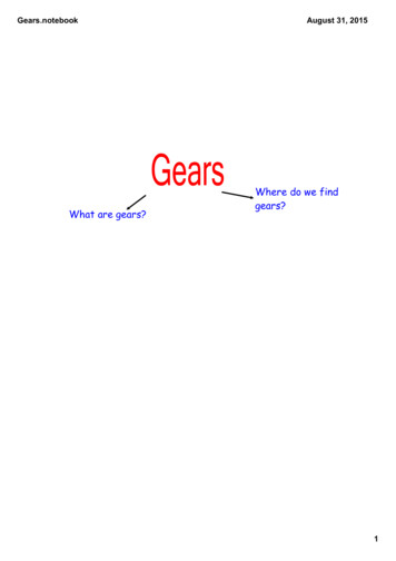
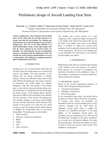
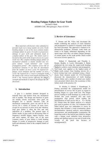
For example, use the following procedure to makea gear 3.250 inches in diameter that has 24 teeth:1. Find the pitch diameter (PD) by using theformula:2. Find the diametral pitch (DP) by using theformula:Figure 14-3.—Measuring gear teeth with a vernier caliper.run from 1 to 48 diametral pitch and 8 cutters to eachpitch.To check the dimensional accuracy of gear teeth,use a gear tooth vernier caliper (see fig. 14-3). Thevertical scale is adjusted to the chordal addendum (a c)and the horizontal scale is used to find the chordalthickness (tc). Before you calculate the chordaladdendum, you must determine the addendum (ADD)and circular thickness (C t).3. Find the whole depth of tooth (WD) by usingthe formula:You can select the cutter to machine the gear teethas soon as you compute the diametral pitch. Formedgear cutters are made with eight different forms(numbered from 1 to 8) for each diametral pitch. Thenumber of the cutter depends upon the number of teeththe gear will have. The following chart shows whichcutter to use to cut various numbers of teeth on a gear.If, for example, you need a cutter for a gear that has24 teeth, use a No. 5 cutter since a No. 5 cutter will cutall gears containing from 21 to 25 teeth.Range of teethNumber of cutter135 to a rack155 to 134235 to 54326 to 34421 to 25517 to 20614 to 16712 to 138To determine the addendum, use the formula:Using the values from the preceding example,To determine the circular thickness, use theformula:Using the values from the preceding example,The formula used to find the chordal addendum isMost cutters are stamped to show the number of thecutter, the diametral pitch, the range for the number ofthe cutter, and the depth. Involute gear cutters usually14-4
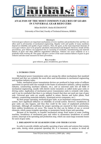
3. Drill and bore to the required size (withintolerance).The formula to find the chordal tooth thickness istc 4. Remove the blank from the lathe and press iton a mandrel.5. Set up the mandrel on the milling machinebetween the centers of the index head and thefootstock. Dial in within tolerance.For example,7. Select a No. 5 involute gear cutter (8 pitch) andmount and center it.tc 8. Set the index head to index 24 divisions. 3 sin 3 45″9. Start the milling machine spindle and move thetable up until the cutter just touches the gearblank. Set the micrometer collar on the verticalfeed handwheel to zero, then hand feed thetable up toward the cutter slightly less than thewhole depth of the tooth. 3 0.0654 3 0.1962 inch10. Cut one tooth groove. Then index the workpiece for one division and take another cut.Check the tooth dimensions with a vernier geartooth caliper as described previously. Make therequired adjustments to provide an accurately“sized” tooth.(NOTE: Mathematics, Volume II-A, NAVEDTRA10062, and various machinist’s handbooks containinformation on trigonometric functions.)Now set the vertical scale of the gear tooth verniercaliper to 0.128 inch. Adjust the caliper so the jawstouch each side of the tooth as shown in figure 14-3. Ifthe reading on the horizontal scale is 0.1962 inch, thetooth has correct dimensions; if the dimension isgreater, the whole depth (WD) is too shallow; if thereading is less, the whole depth (WD) is too deep.11. Continue indexing and cutting until the teethare cut around the circumference of theworkpiece.When you machine a rack, space the teeth bymoving the work table an amount equal to the circularpitch of the gear for each tooth cut. Calculate the circularpitch by dividing 3.1416 by the diametral pitch:Sometimes you cannot determine the outsidediameter of a gear or the number of teeth from availableinformation. However, if you can find a gear dimensionand a tooth dimension, you can put these dimensionsinto one or more of the formulas in Appendix II andcalculate the required dimensions.You do not need to make calculations for correctedaddendum and chordal pitch to check rack teethdimensions. On racks the addendum is a straight linedimension and the tooth thickness is one-half the linearpitch.MACHINING THE GEARUse the following procedures to make a gear withthe dimensions given in the preceding example:1. Select and cut a piece of stock to make theblank. Allow at least 1/8 inch excess materialon the diameter and thickness of the blank forcleanup cuts.A helix is a line that spirals around a cylindricalobject, like a stripe that spirals around a barber pole.2. Mount the stock in a chuck on a lathe. At thecenter of the blank, face an area slightly largerthan the diameter of the required bore.A helical gear is a gear whose teeth spiral aroundthe gear body. Helical gears transmit motion from oneshaft to another. The shafts can be either parallel or setHELICAL GEARS14-5
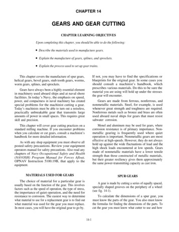
Figure 14-4.—Helical gears.at an angle to each other, as long as their axes do notintersect (fig. 14-4).toward the right, the gear is right-handed. If the helixmoves upward to the left, the gear is left-handed.Helical gears operate more quietly and smoothlythan spur gears because of the sliding action of the spiralteeth as they mesh. Also, several teeth make contact atthe same time. This multitooth contact makes a helicalgear stronger than a comparable spur gear. However,the sliding action of one tooth on another creates frictionthat could generate excessive heat and wear. Thus,helical gears are usually run in an oil bath.To mill a helical gear, you need a dividing head, atailstock, and a lead driving mechanism for the dividinghead (fig. 14-5). These cause the gear blank to rotate ata constant rate as the cut advances. This equipment isan integral part of a universal knee and column type ofmilling machine.When a helical gear is manufactured correctly, itwill mesh with a spur gear of the same diametral pitch(DP), with one gear sitting at an angle to the other. Thedimensions of a helical gear would be the same as thoseof a comparable spur gear if the helical gear’s teeth wereA helical gear can be either right-handed orleft-handed. To determine the hand of a helical gear,simply put the gear on a table with its rotational axisperpendicular to the table top. If the helix moves upward14-6
Page 14-7.Figure 14-5.—A universal horizontal milling machine equipped for helical milling. The closeup shows the workpiece mounted between the dividing head centers. A fluting cutteris mounted on the arbor.
Figure 14-6.—Development of evenly spaced slots with anincluded angle.not cut at an angle. One of these differences is shown inthe following example:Figure 14-7.—Development of the helix angle.You will need a 10-inch circular blank to cut 20one-quarter-inch wide slots spaced one-quarterof an inch apart parallel to the gear’s axis ofrotation. But you will need a 10.6-inch circularblank to cut the same slots at an angle of 19 22 to the axis of rotation (fig. 14-6).The lead of a helical gear is the longitudinaldistance a point on the gear travels during one completerevolution of the gear. During the gear manufacturingprocess, lead relates to the travel of the table.The helix angle is the angle between a plane parallelto the rotational axis of the workpiece and the helix linegenerated on the workpiece. Use this angle to set themilling machine table to cut the gear. Also use it toestablish the relationships between the real dimensionsand the normal dimensions on a helical gear.Helical gears are measured at a right angle to thetooth face in the same manner as spur gears with thesame diametral pitch.DIMENSIONS OF A HELICAL GEAR,REAL AND NORMALDetermining the Dimensions of a Helical GearThe RPD is the easiest helical gear dimension todetermine. Simply subtract twice the addendum fromthe ROD, orEvery helical gear contains a theoretical spur gear.Any gear element formula used to calculate a spur geardimension can also be used to determine an equivalenthelical gear dimension. However, the helical geardimension is known as a normal dimension. Forexample, the number of teeth (NT) on a helical gear isconsidered a normal dimension. Remember, though, allnormal gear elements are calculated dimensions andtherefore cannot be measured.For example:RPD ROD - 2 ADDTo determine the other major dimensions, you mustrelate real and normal dimensions trigonometricallythrough the helix angle. Then by knowing two of thethree components of the trigonometric relationship, youcan determine the third component.Look at figure 14-7, view A, and recall that the helixangle is the angle between the gear’s axis of rotation andthe helix. In this view, the RPD and the NPD are relatedthrough the secant and cosine functions. That is, Normal pitch diameter (NPD)Although most helical gear dimensions are normaldimensions, a few dimensions are real (measurable)dimensions. Examples of real dimensions are theoutside diameter (OD), called the real outside diameter(ROD), and the pitch diameter, called the real pitchdiameter (RPD). Two other real dimensions are the leadIn figure 14-7, view B, the triangle has beenmathematically shifted so we can compare the realchordal thickness (CTR) and the normal chordaland the helix angle14-8
Figure 14-9.—Helix cut with two different cutters.Figure 14-8.—Formulation of a lead triangle and a helix angle.Figure 14-10.—Formation of helical gear cutter selection.thickness (CTN). The CTR is the thickness of the toothmeasured parallel to the gear’s face, while the CTN ismeasured at a right angle to the face of the tooth. Thetwo dimensions are also related through the secant andcosine functions. That is,Selecting a Helical Gear CutterWhen you cut a spur gear, you base selection of thecutter on the gear’s DP and on the NT to be cut. To cuta helical gear, you must base cutter selection on thehelical gear’s DP and on a hypothetical number of teethset at a right angle to the tooth path. This hypotheticalnumber of teeth takes into account the helix angle andthe lead of the helix, and is known as the number of teethfor cutter selection (NTCS). This hypothetical development is based on the fact that the cutter follows anelliptical path as it cuts the teeth (fig. 14-9).If we could open the gear on the pitch diameter(PD), we would have a triangle we could use to solvefor the lead (fig. 14-8, view A).Figure 14-8, view B, shows a triangle; one leg is thereal pitch circumference and the other is the lead. Noticethat the hypotenuse of the triangle is the tooth path andhas no numerical value.To solve for the lead of a helical gear, when youknow the RPD and the helix angle, simply change RPDto RPC (real pitch circumference). To do that, multiplyRPD by 3.1416 (π) (fig. 14-8, view C), then use theformula:The basic formula to determine the NTCS involvesmultiplying the actual NT on the helical gear by the cubeof the secant of the helix angle, orNTCS NT secThis formula is taken from the triangle in figure14-10.Lead RPC Cotangent14-9
Table 14-1.—"K" Factor TableTable 14-2.—Corrected Tooth Constant14-10
It can be complicated to compute the NTCS withthe formula, so table 14-1 provides the data for asimplified method to cube the secant of the helix angle.To use it, multiply the NT by a factor (K) you obtainfrom the table.Table 14-3.—Maximum Backlash AllowanceNTCS NT K (factor)To determine the constant K, locate on table 14-lthe helix angle you plan to cut. If the angle is other thana whole number, such as 15 6 , select the next highestwhole number of degrees, in this case 16 . The factorfor 15 6 is 1.127.The following section will show you how to use thenumerical value of the NTCS to compute correctedchordal addenda and chordal thicknesses.Corrected Chordal Addendumand Chordal ThicknessAs in spur gearing, you must determine correctedchordal addenda and chordal thicknesses since you willbe measuring circular distances with a gear toothvernier caliper that was designed to measure onlystraight distances.In helical gearing, use the NTCS rather than theactual NT to select the constant needed to determine thechordal addendum (CA) and the chordal thickness(CT). Table 14-2 provides these constants. Remember,the numbers listed in the Number of Teeth column arenot actual numbers of teeth, but are NTCS values. Afteryou have determined the chordal addendum and chordalthickness constants, you can calculate the correctedchordal addendum by using the following formula:NOTE: If the calculated NTCS is other than a wholenumber, go to the next highest whole number.From table 14-2, an NTCS of 23 provides thefollowing:CA constant 1.0268; CT constant 1.56958Therefore, CADD CCT 0.102680 and 0.156958Backlash Allowance for Helical Gearsand the corrected chordal thicknesss by using thisformula:The backlash allowance for helical gears is the sameas that for spur gears. Backlash is obtained bydecreasing the thickness of the tooth at the pitch lineand should be indicated by a chordal dimension. Table14-3 gives maximum allowable backlash in inchesbetween the teeth of the mating gears.As an example, calculate the corrected chordaladdendum and the corrected chordal thickness for ahelical gear with a DP of 10, a helix angle of 15 , and20 teeth.To determine the proper amount of backlash,multiply the maximum allowable amount of backlashfound in table 14-3, part A, by 2 and add the result tothe calculated whole depth. In this case the maximumbacklash allowance is a constant.NTCS NT K 20 1.11 (constant from table 14-l) 2314-11
Figure 14-11.—Standard universal dividing head driving mechanism connected to the dividing head, and showing the location ofchange gears’s A, B, C, and D.Center-to-Center DistanceGEAR TRAIN RATIOWe said earlier in this chapter that the main purposeof gearing is to transmit motion between two or moreshafts. In most cases these shafts are in fixed positionswith little or no adjustments available. Therefore, it isimportant for you to know the center-to-center (C-C)distance between the gear and the pinion.When a helix is milled on a workpiece, theworkpiece must be made to rotate at the same time it isfed into the revolving cutter. This is done by gearing thedividing head to the milling machine table screw. Toachieve a given lead, you must select gears with a ratiothat will cause the work to rotate at a given speed whileit advances a given distance toward the cutter. Thisdistance will be the lead of the helical gear. The lead ofthe helix is determined by the size and the placement ofthe change gears, labeled A, B, C, and D in figure 14-11.Gears X and Y are set up to mill a left-handed helix.You can set a right-handed helix by removing gear Yand reversing gear X.If you know the tooth elements of a helical gear,you can say that when the real pitch radius of the gear(RPRg) is added to the real pitch radius of the pinion(RPRp), you can determine the C-C distance of the twogears (gear and pinion).The ratio of the NT on the gear and the pinion isequal to the ratio of the PD of the gear and the pinion.This will allow you to solve for the necessary elementsof both gear and the pinion by knowing only the C-Cdistance and the ratio of the gear and the pinion.Before you can determine which gears are requiredto obtain a given lead, you must know the lead of themilling machine. The lead is the distance the milling14-12
machine table must move to rotate the spindle of thedividing head one revolution. Most milling machineshave a table screw of 4 threads per inch with a lead of0.250 inch (1/4 inch) and a dividing head (index head)with a 40:1 worm-to-spindle ratio. When the index headis connected to the table through a 1:1 ratio, it will cuta lead of 10 inches. Thus, 40 turns of the lead screw arerequired to make the spindle revolve one completerevolution (40 0.250 inch 10 inches). Therefore,10 will be the constant in our gear train ratio formula,orThus, gears with 40 and 24 teeth become the drivinggears, and gears with 40 and 36 teeth become the drivengears.These gears would be arranged in the gear train asfollows:Gear A (on the dividing-head worm shaft)All ratios other than 1:1 require modification of the geartrain.40 teeth (driven)Gear B (first gear on the idler stud)From this formula, we can also say that the24 teeth (driving)Gear C (second gear on the idler stud)36 teeth (driven)Gear D (gear on the table screw)40 teeth (driving)Example:The positions of the driving gears may beinterchanged without changing their products. Thesame is true of the driven gears. Thus, several differentcombinations of driving and driven gears will producea helix with the same lead.Determine the change gears required for a lead of15 inches. Assume the milling machine has a lead of 10inches.If you could use a simple gear train (one driving andone driven gear), a lo-tooth gear on the table screwmeshed with a 15-tooth gear on the dividing-head wormshaft would produce the 15-inch lead required.However, gears of 10 and 15 teeth are not available, andthe drive system is designed for a compound gear trainof four gears. Therefore, the fraction 10/15 must be splitinto two fractions whose product equals 10/15. Do thisby factoring as follows:Before you start to figure your change gear, checkyour office library for a ready-made table for theselection of gears devised by the Cincinnati MillingMachine Company. These gears have been determinedusing the formula,. If you have already calculatedyour lead, match it with the lead in the table and selectthe gears for that lead.MANUFACTURING A HELICAL GEARAt this point of the chapter, you are ready tomanufacture a helical gear. In a case where you mustmanufacture a helical gear from a sample, you shoulddo the following:If gears with 5 and 2 teeth were possible, they wouldbe the driving gears, and gears with 5 and 3 teeth wouldbe the driven gears. But since this is not possible, eachof the fractions must be expanded by multiplying boththe numerator and the denominator by a number thatwill result in a product that corresponds to the numberof teeth on available gears:1. Find the DP.2. Measure the OD. This is also the ROD.3. Find the ADD.4. Find the RPD.5. Find the NT.14-13
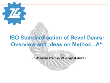
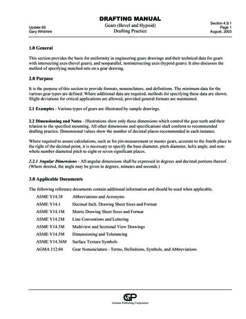
6. Find the NPD.7. Find the8. Find the RPC.9. Find the lead.10. Find the change gear.11. Find the NTCS.12. Make sure the cutter has the correct DP andcutter number.13. Find your corrected chordal addendum andchordal thickness.14. Find your corrected whole depth (WD).15. Determine what kind of material the samplegear is to be made of.Figure 14-12.—Bevel gear and pinion.Now you are ready to machine your gear.Use the following hints to manufacture a helicalgear:1. Make all necessary calculations that are neededto compute the dimensions of the gear.2. Set up the milling machine attachments formachining.3. Select and mount a gear cutter. Use the formula4. Swivel the milling machine table to the helixangle for a right-hand helix; face the machineand push the milling machine table with yourright hand. For a left-hand helix, push the tablewith your left hand.5. Set the milling machine for the proper feedsand speeds.A. With shafts less than 90 apartB. With shafts more than 90 apart6. Mount the change gears. Use the gear trainratio formula to determine your change gears.Figure 14-13.—Other forms of bevel gears.7. Mount the gear blank for machining.8. Set up the indexing head for the correct numberof divisions.9. Before cutting the teeth to the proper depth,double check the setup, the alignment, and allcalculations.10. Now you are ready to cut your gear.11. Remove and deburr the gear.BEVEL GEARSBevel gears have a conical shape (fig. 14-12) andare used to connect intersecting shafts. Figure 14-13,view A, shows an example of bevel gears with shaftsset at less than 90 . View B shows those set at more than90 . There are several kinds of bevel gear designs. Wewill discuss the straight-tooth design because it is themost commonly used type in the Navy. The teeth are14-14
straight but the sides are tapered. The center line of theteeth will intersect at a given point.Bevel gears are usually manufactured on gearcutting machines. However, you will occasionally haveto make one on a universal milling machine.This section of the chapter deals with the anglenomenclature of a bevel gear as well as the developmentof the triangles needed to manufacture one.When two bevel gears whose shaft angles equal 90 are in mesh (fig. 14-14, view A) they form a triangle. Itis called the mating gear triangle. The cones (fig. 14-14,view B) that form the basis of the bevel gears are calledthe pitch cones. These cones are not visible at all on thefinished gear, but they are important elements in bevelgear design.The angle that is formed at the lower left-handcorner of the triangle (fig. 14-14, view C) is called thepitch cone angle of the pinion. The altitude of thetriangle is called the pitch diameter of the pinion, andits base is called the pitch diameter of the gear.The hypotenuse of the triangle is twice the pitchcone radius.The pitch diameter (gear and pinion), the numberof teeth (gear and pinion), and the actual ratio betweenthe gear and the pinion are all in ratio. Therefore, wecan use any of these three sets to find the pitch coneangle (PCA).Example: A 10 diametral pitch (DP) gear with 60teeth has a pitch diameter (PD) of 6 and a 10 DP pinionwith 40 teeth has a PD of 4. Therefore, the ratio of thegear and the pinion is 3:2.We can determine the PCA by simply substitutingthe known values into the formula:orFigure 14-14.—Development of the mating gear triangle.NOTE: The pitch cone angle of the pinion (PCA p)is the compliment of the pitch cone angle of the gear(PCAg).14-15
FA - Face anglePCA - Pitch cone angleCA - Cutting angleADD - Addendum angleDED - Dedendum angleBCA - Back cone anglePD - Pitch diameterOD - Outside diameterANG ADD - Angular addendumFW - Face widthPCR - Pitch cone radiusPR - Pitch radiusADD - AddendumDED - DedendumFigure 14-15.—Parts of a bevel gear.BEVEL GEAR NOMENCLATURE2. Pitch cone angle (PCA orThe dimension nomenclature of the bevel gear isthe same as that of a spur gear, with the exception of theangular addendum. Refer to figure 14-15.a. This angle is formed by a line down oneaddendum on the tooth and the axis of thegear.1. Face angle (FA)b. This
10062, and various machinist’s handbooks contain information on trigonometric functions.) Now set the vertical scale of the gear tooth vernier caliper to 0.128 inch. Adjust the caliper so the jaws touch each side of the tooth as shown in figure 14-3. I