Transcription
International Journal of Engineering Research & Technology (IJERT)ISSN: 2278-0181Vol. 2 Issue 6, June - 2013Bending Fatigue Failure In Gear ToothArvind S. Kale.AISSMS COE, Shivajinagar, Pune-4110192. Review of LiteratureAbstractRobert F. Handschuh and Timothy L.Krantz, Bradley A. Lerch, Christopher S. Burkeconducted the test using the single-tooth bendingmethod to achieve crack initiation and propagation.Test loads were applied at the highest point ofsingle tooth contact. Gear bending stresses for agiven testing load were calculated using a linearelastic finite element model [2]. P.J.L.Fernandesdiscussed the characteristics of tooth bendingfatigue failure and a number of actual case studieswere presented which shows the occurrence of thisfailure mode in the practice [3].IJERTMost materials will fracture when submitted toperiodic loads over a large number of cycles. Toothbending fatigue is one of the most common modesof fatigue failure in gears. It results in progressivedamage to gear teeth and ultimately leads tocomplete failure of the gear. The initial crack islocated at the point of the largest stresses in a geartooth root. The complete bending fatigue failure ofmechanical elements is mainly divided into twoparts namely „„crack initiation” and „„crackpropagation period‟‟. The complete service life ofmechanical elements N can then be determinedfrom the number of stress cycles Ni required forfatigue crack initiation and the number of stresscycles Np required for a crack to propagate fromthe initial to the critical crack length and failure as,N Ni Np. Various factors affecting the fatiguestrength and methods to improve the fatigue life arediscussed.T. Osman and Ph. Velex had developed themodel combining the analysis of crack initiationand propagation in relation to dynamic tooth loadshas been presented. The approach is limited to bidimensional problems. Dynamic tooth loads arefound to be highly influential depending on thespeed range since they can induce fatigue damagesat certain points on the tooth profile which wouldnot occur at lower speeds [1].1. IntroductionA gear is a machine element designed totransmit force and motion from one mechanicalunit to another. The design and function of gearsare usually closely associated, since gears aredesigned for a specific function. Like allmechanical components, gears can and do fail inservice for a variety of reasons. In most cases,except for an increase in noise level and vibration,total gear failure is often the first and onlyindication of a problem. The general types offailure modes in gear teeth (in decreasing order offrequency) include fatigue, impact fracture, wearand stress rupture. Of these, one of the mostcommon causes of gear failure is tooth bendingfatigue. It results in progressive damage to gearteeth and ultimately leads to the complete failure ofthe gear.IJERTV2IS60387D. Jelaska, S. Glodež, J. Kramberger, S.Podrug presented the computational model fordetermination of service life of gears in regard tobending fatigue in a gear tooth root. The fatigueprocess leading to tooth breakage in a tooth root isdivided into crack initiation (Ni) and crackpropagation (Np) period, which enables thedetermination of total service life as N Ni Np[4]. Osman done the failure analysis of a helicalgear used in gearbox of a bus. An evaluation of thefailed helical gear was undertaken to assess itsintegrity that included a visual examination, photodocumentation, chemical analysis, micro-hardnessmeasurement, and metallographic examination. Hefound that teeth of the helical gear failed by fatiguewith a fatigue crack initiation from destructivepitting and spalling region at one end of tooth in thevicinity of the pitch line because ofmisalignment[5].www.ijert.org802
International Journal of Engineering Research & Technology (IJERT)ISSN: 2278-0181Vol. 2 Issue 6, June - 2013train, resulting in force called the dynamic load.The following items cause this load.3. Causes of Breakage FailureFatigue is the most common failure ingearing. Tooth bending fatigue and surface contactfatigue are two of the most common modes offatigue failure in gears. Several causes of fatiguefailure have been identified. These include poordesign of the gear set, incorrect assembly ormisalignment of the gears, overloads, inadvertentstress raisers or subsurface defects in critical areas,and the use of incorrect materials and heattreatments [6].3.1. Incorrect Assessment of LoadThe load imposed during the operation hasnot been ascertained properly due to limitations ofdata available.3.2. Impact LoadsThe impact loads faced by the teeth due toshocks have not been taken into account for loadcalculations .The impact loads due to shocks maybe as a result of characteristics of the drive.3. Gear inertia, which is dependent on gearmass and pitch-line velocity.3.6. Stress RisersMost failures result from excessive toothload, which result in root stress higher than theendurance limit of the material. Then gears areloaded in this manner and subjected to enoughrepeated cycles, the gear teeth will fail. Sometimesstress risers, help to aggravate this condition andsubject the gear teeth to higher root stress levelsthan would normally be predicted. Such risersincludes notches in root fillets, hob tears,inclusions, small heat-treat cracks, grinding burnsand residual stresses.4. Tooth Bending FatigueIncorrect choice of material may occur insome cases due to mix-up of material at productionstage wherein gears may be produced of wrongmaterial without the mistake being detected. Itcould as well be the result of wrong choice ofmaterial at design stage by understanding the load.There is disagreement among the gear designerswhether the Izod test value can indicate thesensitivity of tooth breakage to impact load.However, tough steel is definitely better than abrittle one. Failure of gear tooth solely due to theuse of steel having low Izod value is almostunknown.3.4. Increased Load due to Mal-distributionof LoadIncreased load is faced by gear due to errorsin mountings (misalignment of axes), errors inhelix angles and errors in manufacture due todistortion, such as heat treatment distortion. Due tothis, gear does not have the full length contact asassumed in gear design, but has reduced contact,which increases the load on gear tooth.Maldistribution of load also arises from lack ofrigidity in structure supporting the gears.3.5 Errors in Gear TeethErrors in gear teeth change the relativevelocity of the mating gear. This causes themomentary acceleration and deceleration of gearIJERTV2IS603872. Tooth stiffness variation due to toothgeometry and variation in elasticity of material.IJERT3.3. Incorrect Choice of Material1. Tooth errors, such as spacing error, profileerror, lead error, and pith line run out.Surface contact fatigue of gear teeth is oneof the most common causes of gear operationalfailure due to excessive local Hertzian contactfatigue stresses. Generally, there are two types ofsurface contact fatigue, namely, pitting andspalling. The pitting of gear is characterised byoccurrence of small pits on the contact surface.Pitting originates from small, surface or subsurfaceinitial cracks, which grow under repeated contactloading. Pitting is a three-dimensional phenomenonand strongly depends on contact surface finish,material microstructure and operating conditions,such as type of contact, loading, misalignment,lubrication problems, temperature, etc. Spalling, ingeneral, is not considered an initial mode of failurebut rather a continuation or propagation of pittingand rolling contact fatigue. Although pittingappears as shallow craters at contact surfaces,spalling appears as deeper cavities at contactsurfaces [5].Gearboxes are generally robust and reliabledevices. However, problems do occur particularlydue to application error. Application errors can becaused by a number of problems, includingmounting and installation, vibration, cooling,lubrication, and maintenance. Misalignment isprobably the most common, single cause of failure,Due to misalignment; the pinion does not meshproperly with the gear during operation, and thislead to a high stress concentration at the surface ofwww.ijert.org803
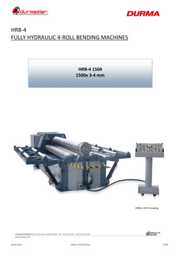
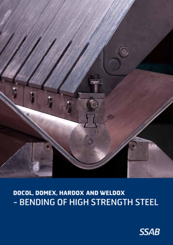
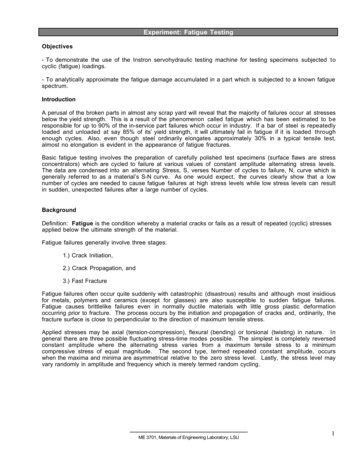
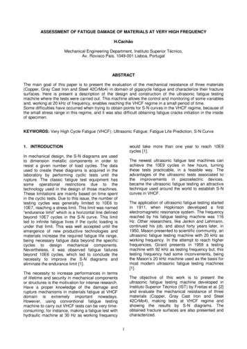
International Journal of Engineering Research & Technology (IJERT)ISSN: 2278-0181Vol. 2 Issue 6, June - 2013gears. The misalignment also leads to severe wearand excessive heat generation at the mating surface.In gears, it is exhibited as premature pitting at oneend of the tooth. There are many causes ofmisalignment, both static (manufacturing orsetting-up errors) and dynamic, due to elasticdeflections of components under load, and also dueto thermal expansion. Also, damage to and failuresof gears in gearbox can and do occur as a direct orindirect result of lubrication problems [5].Several classical standardized procedures(DIN, AGMA, ISO, etc.) can be used for theapproximate determination of load capacity of geartooth root. They are commonly based on thecomparison of the maximum tooth-root stress withthe permissible bending stress [1]. Theirdetermination depends on a number of differentcoefficients that allow for proper consideration ofreal working conditions (additional internal andexternal dynamic forces, contact area of engaginggears, gear’s material, surface roughness, etc.). Theclassical procedures are exclusively based on theexperimental testing of the reference gears and theyconsider only the final stage of the fatigue processin the gear tooth root, i.e. the occurrence of finalfailure.IJERTThe stresses on a gear tooth can be analyzedby considering the tooth to be a short cantileverbeam with the load applied at the bearing surface.This is shown schematically in Figure 1. Themaximum tensile stresses occur at the root radiuson the active (i.e. loaded) flank of the gear tooth,while the maximum compressive stresses occur atthe root radius on the passive flank. A zero-stresspoint therefore exists below the root circle at ornear the tooth centre-line. Depending on thegeometry of the gear tooth and the characteristicsof loading, the stress concentration at the rootradius where maximum tensile stresses areexperienced may vary from 1.4 to 2.5. With thecyclic variation in loads characteristic of gearoperation, these regions become preferential sitesfor fatigue crack initiation [3].As the fatigue crack propagates, the crackedtooth is deflected, thus allowing the adjacent gearteeth to pick up the load. The higher loads on theseteeth, in turn, impose higher stresses at thecorresponding root radii and lead to further fatiguecrack initiation. As a result, tooth bending fatigueusually leads to failure of a number of adjacentgear teeth [3].Figure 1. A Gear Tooth as a Small Cantilever BeamOnce a fatigue crack initiates at the rootradius, it propagates towards the zero-stress point,which is initially below the root circle near thetooth centre-line .However, as crack propagationproceeds, the zero-stress point is displaced laterallyuntil it reaches a position under the opposite root.At this stage, the shortest untracked section liesbetween the crack tip and the opposite root, andfinal crack growth proceeds in this direction. Thisresults in the L-shaped crack paths often observedin practice [3].IJERTV2IS603875. Fatigue Failure ProcessHowever, the complete process of fatiguefailure of mechanical elements may be divided intothe following stages [4].(1) Micro crack nucleation;(2) Short crack growth;(3) Long crack growth; and(4) Occurrence of final failure.In engineering applications the first twostages are usually termed as “crack initiationperiod”, while Long crack growth is termed as“crack propagation period”. An exact definition ofthe transition from initiation to propagation periodis usually not possible. However, the crackinitiation period generally account for most of theservice life, especially in high cycle fatigue, seeFigure 2. The total number of stress cycles N canthen be determined from the number of stresscycles Ni required for the fatigue crack initiationand the number of stress cycles Np required for acrack to propagate from the initial to the criticalcrack length, when the final failure can be expectedto occur.www.ijert.orgN Ni N p(1)804
International Journal of Engineering Research & Technology (IJERT)ISSN: 2278-0181Vol. 2 Issue 6, June - 2013Where Δσ is the applied stress range and ki and Ciare the material constants. It is easy to obtain thecrack initiation life Ni using this relation, if weassume that the crack initiation curve passes thesame point (NFL; ΔσFL) as the Wohler curve, itmeans at the fatigue limit level the whole fatiguelife consists of the crack initiation period [4].Figure-2.The service life of mechanical elements6. Fatigue Crack InitiationWhere σU is the ultimate strength, seeFigure 2. This relation was found to be in a goodcorrelation with available experimental results. Themost important parameter when determining thecrack initiation life Ni according to equation (4) isthe fatigue limit ΔσFL, which is a typical materialparameter and is determined using appropriate testspecimen. When determining the fatigue limit forgears, the reference test gears are usually used asthe test specimens. According to ISO standard, theyare spur gears with normal module mn 3 to 5 mm,tooth width B 10 to 50 mm, surface roughnessRz 10 μm, etc, which are loaded with repeatedpulsating tooth loading. If geometry, surfaceroughness, gear size and loading conditions of realgears in the praxis deviate from the referencetesting, the previously determined fatigue limitΔσFL must be modified through the appropriatecorrelation factors.IJERTThe initiation of fatigue cracks representsone of the most important stages in the pittingprocess. The position and mode of fatigue crackinitiation depends on the microstructure of thematerial, the type of stress and the micro- andmacro-geometry of the specimen [1].The material is often considered ashomogenous with no defects such as inclus
Osman done the failure analysis of a helical gear used in gearbox of a bus. An evaluation of the failed helical gear was undertaken to assess its integrity that included a visual examination, photo documentation, chemical analysis, micro-hardness measurement, and metallographic examination. He found that teeth of the helical gear failed by fatigue with a fatigue crack initiation from .