Transcription
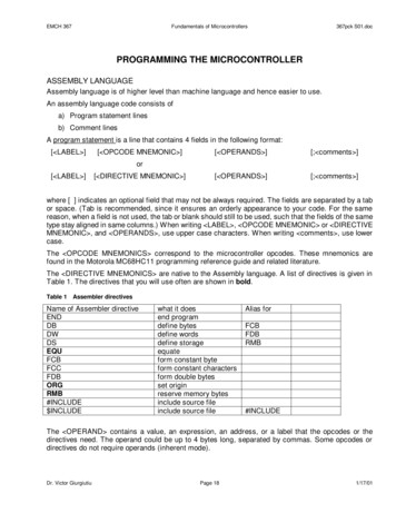
EMCH 367Fundamentals of Microcontrollers367pck S01.docPROGRAMMING THE MICROCONTROLLERASSEMBLY LANGUAGEAssembly language is of higher level than machine language and hence easier to use.An assembly language code consists ofa) Program statement linesb) Comment linesA program statement is a line that contains 4 fields in the following format:[ LABEL ][ OPCODE MNEMONIC ][ OPERANDS ][; comments ][ OPERANDS ][; comments ]or[ LABEL ][ DIRECTIVE MNEMONIC ]where [ ] indicates an optional field that may not be always required. The fields are separated by a tabor space. (Tab is recommended, since it ensures an orderly appearance to your code. For the samereason, when a field is not used, the tab or blank should still to be used, such that the fields of the sametype stay aligned in same columns.) When writing LABEL , OPCODE MNEMONIC or DIRECTIVEMNEMONIC , and OPERANDS , use upper case characters. When writing comments , use lowercase.The OPCODE MNEMONICS correspond to the microcontroller opcodes. These mnemonics arefound in the Motorola MC68HC11 programming reference guide and related literature.The DIRECTIVE MNEMONICS are native to the Assembly language. A list of directives is given inTable 1. The directives that you will use often are shown in bold.Table 1Assembler directivesName of Assembler directiveENDDBDWDSEQUFCBFCCFDBORGRMB#INCLUDE INCLUDEwhat it doesend programdefine bytesdefine wordsdefine storageequateform constant byteform constant charactersform double bytesset originreserve memory bytesinclude source fileinclude source fileAlias forFCBFDBRMB#INCLUDEThe OPERAND contains a value, an expression, an address, or a label that the opcodes or thedirectives need. The operand could be up to 4 bytes long, separated by commas. Some opcodes ordirectives do not require operands (inherent mode).Dr. Victor GiurgiutiuPage 181/17/01
EMCH 367Fundamentals of Microcontrollers367pck S01.docThe constants used in the OPERAND can be hex, decimal, binary, or octal numbers. Table 2 givesthe assembler symbols used to this purpose.Table 2Assembler symbols for constantsSymbolMeaningExample number hex number A1 number decimal number20% number binary number%11001010@ number octal number@73‘ string ’, ‘ string ASCII string‘A’or ‘A (the latter does not work with #INCLUDE)The expressions used in the OPERAND can use any of the operators listed in Table 3Table 3 Assembler symbols for expressionsSymbolMeaningExample-unary minus-4&binary AND%11111111&%10000000!binary OR%11111111!%10000000 multiplication3 2A/division 7E/3 addition1 2-subtraction3-1parentheses used for grouping3 (1 2)( )Important conventions used in the OPERAND are given in Table 4:Table 4 Other important conventionsSymbolMeaningExample#immediate mode (IMM)# A3;start of comment line and of comment insideLDAAa program statement*alternate sign for start of comment line only* This is a comment,Xindex X mode (IND,X)LDAA TFLG1,X,Yindex X mode (IND,Y)LDAA TFLG2,YDr. Victor GiurgiutiuPage 19# FF; Load accA1/17/01
EMCH 367Fundamentals of Microcontrollers367pck S01.docThe LABEL is a very powerful concept that can greatly simplify the programmer’s task. The LABEL consists of a string of alphanumeric characters that make up a name somehow meaningful tothe programmer. The placement of the LABEL can be in one of the following positions:a) In the first column and terminates with a tab or blank characterb) In any column and terminates with a colon (:)There are 3 different usages of the LABEL :1) To assign the name inserted in the LABEL to a location in a program. The LABEL will be assigned the address of that location2) To assign the value of an expression or constant to the name inserted in the LABEL using the EQU (equate) or SET directives.3) To define the name of a subroutine (macro). Essentially, this is the same as 1), since anaddress (the subroutine starting address) is assigned to the label.When labels are assigned to certain addresses, one can tell the program to go to that address byreferring to the label (case 1 above). Alternatively, one can use the contents of a certain address byreferring to its label, just like when using variables (case 2 above).A comment is prefixed by semicolon (;).When the assembler detects an semicolon, it knows that therest of the line is a comment and does not expect any executable instructions from it. A comment canbe a separate line (comment line) or can be inserted in a program statement. A comment line can bealso prefixed by an asterisk ( ). The comments, either in the comment field or as a separate commentline, are of great benefit to the programmer in debugging, maintaining, or upgrading a program. Acomment should be brief and specific, and not just reiterate its operation. A comment that does notconvey any new information needs not be inserted. When writing a comment, use lower casecharacters.A program written in Assembly language is called source file. Its extension is .ASM. When the sourcefile is assembled, two files are generated:a)Object file that can be run in the microcontroller. The Motorola object file is in ASCII-HEXformat. Its generic name is “S19 file’. Its extension is .S19b)List file, extension .LST, that contains the original code in Assembly language and thecorresponding hex codes resulting from the Assembly process. The list file is used by theprogrammer to verify and debug his/her coding of the program.The .ASM files can be opened, viewed, edited and saved in the THRSIM11 application. Alternatively, allthree file types (.ASM, .LST, .S19) can be also processed in a text editor, e.g., the Notepad application.Examples of .ASM and .LST files follow.Addressing ModesInherent Mode is implied and requires no programming action.Immediate Mode means that the number contained in the operand will be immediately used.Direct and Extended Modes use the number contained in the operand to signify an address where therequired information should be retrieved from or deposited to. The Extended mode is automaticallyused for addresses greater than FF.Index Mode is used by adding the operand to the value already existing in the Index X or Y, asselected. In this case, the operand acts as an offset.Relative Mode uses the operand as an offset relative to the present Program Counter value.Dr. Victor GiurgiutiuPage 201/17/01
EMCH 367Fundamentals of Microcontrollers367pck S01.docMICROCONTROLLER COMMANDS(Section 6 and Section A of M68HC11 Reference Manual)The 6811 microcontroller has 145 different commands. These commands can be grouped into severalcategories. The categories and the commands in those categories are listed below:1) Arithmetic operations:a) Addition:ABA, ABX, ABY, ADCA, ADCB, ADDA, ADDB, ADDD, INC, INCA, INCB, INS, INX, INYb) Subtraction:SBA, SBCA, SBCB, SUBA, SUBB, SUBD, DEC, DECA, DECB, DES, DEX, DEYc) Multiplication: MULd) Division: FDIV, IDIV2) Logical operations: (note: logical operations are carried out on a bit by bit basis)a) Standard logical operations: ANDA, ANDB, EORA, EORB, ORAA, ORAB, COM (Booleaninverse), COMA, COMBb) Operations that shift the location of the bits in the register:ASL, ASLA, ASLB, ASLD, ASR, ASRA, ASRB, LSL, LSLA, LSLB, LSLD, LSR, LSRA, LSRB,LSRD, ROL, ROLA, ROLB, ROR, RORA, RORBc) Operations that compare two numbers:BITA, BITB, CBA, CMPA, CMPB, CPD, CPX, CPY3) Branching commands: BCC, BCS, BEQ, BGE, BGT, BHI, BHS, BLE, BLO, BLS, BLT, BMI, BNE,BPL, BRA, BRCLR, BRN, BRSET, BSR, BVC, BVS, JMP, JSR, RTS, RTI, WAI4) Memory/Register Functions5)6)a) Move data into / out of memory: LDAA, LDAB, LDD, LDS, LDX, LDY, STAA, STAB, STD, STS,STX, STYb) Change the values in memory/registers: BCLR, BSET, CLC, CLI, CLR, CLRA, CLRB, CLV,COM, COMA, COMB, NEG, NEGA, NEGB, SEC, SEI, SEVc) Transfer data from one register to another: TAB, TAP, TBA, TPA, TSX, TSY, TXS, TYS,XGDX, XGDYStack Pointer Functions: PSHA, PSHB, PSHX, PSHY, PULA, PULB, PULX, PULYMisc.: NOP, SWINote: Boolean inversion commands: COM, COMA, COMBDr. Victor GiurgiutiuPage 211/17/01
EMCH 367Fundamentals of Microcontrollers367pck S01.docSAMPLE PROGRAM IN ASSEMBLY LANGUAGE WITH MCU COMMANDSPROBLEM STATEMENTThis simple program is an example of addition. It performs the operation:VAR0 VAR1 à SUMIn addition, the program checks if an overflow happened during the addition process, and sets the flagOVERFL accordingly.PROGRAM DESCRIPTION The variables are defined in lower memory starting with 0000, in the order VAR0, VAR1, SUM,OVERFL. LDAB with zero is used to reset the initial value of the overflow flag (optimistic!). LDAA is used to load VAR0 into AccA ADDA is used to add accA with VAR1. Result of addition stays in accA BVC is used to branch over the next instruction, i.e. to LABEL1, if no overflow occurred If an overflow occurred during the addition process, this instruction is reached and COMB isused to invert accB from 00 to FF. Label1: STAA is used to store the result of addition from accA into SUM STAB is used to store accB ( 00 or FF, depending on the logic just discussed) into theoverflow flag OVERFLFLOWCHARTFLOWCHARTInitialize variables:àVAR0àVAR1àSUMàOVERFL 0000 0001 0002 0003Load 00 into accB as the initial (optimistic)guess for the overflow statusLoad first variable into accAAdd second variable to accA(result stay in ac cA)Brach if overflow bitis clearYNSince overflow bit was not clear, Invert accBLABEL1Store result of addition from accA into SUMStore current value of overflow flag fromaccB into OVERFLSWIDr. Victor GiurgiutiuPage 221/17/01
EMCH 367Fundamentals of Microcontrollers367pck S01.docASSEMBLY (.ASM) CODE*********DEMO.ASMThis simple program adds the contents ofaddress 0000 (labeled VAR0) to the contents ofaddress 0001 (labeled VAR1) and stores the resultingsum at address 0002 (labeled SUM), providedthe addition process happens without overf low.If an overflow occurs during the addition process,the overflow flag OVERFL (stored at address 0003)is set to FF; else, it stays 00.* Include definition of variables for MC68HC11#INCLUDE'A:\VAR DEF.ASM'* Define program MRMB1;reserveOVERFL RMB1;reserve* Start main programORGPROGRAMLDAB#00LDAAVAR0ADDAVAR1BVCLABEL1* We have overflow!COMBLABEL1 orVAR0VAR1sumoverflow flag;assume no overflow (optimistic!);load VAR0 in accumulator A;add VAR1 to accumulator A;jump if no overflow;Invert accumulator B ( 00 to FF);store result of addition;store accB into overflow flag;stop the microcontrollerLIST (.LST) OUTPUT RESULTING AFTER erandcommentsDEMO.lst - generated by MiniIDE's ASM12 V1.07b Build 52 [12/29/1999, 16:30:49]1:2:3:4:5:6:7:8:9:10:11:12:13:Dr. Victor Giurgiutiu*12456789012345678901245678901234567 890124567890123456789******DEMO.ASMThis simple program adds the contents ofaddress 0000 (labeled VAR0) to the contents ofaddress 0001 (labeled VAR1) and stores the resultingsum at address 0002 (labeled SU M), providedthe addition process happens without overflow.* If an overflow occurs during the addition process,* the overflow flag OVERFL (stored at address 0003)* is set to FF; else, it stays 00.Page 231/17/01
EMCH 52:53:54:55:56:Fundamentals of Microcontrollers367pck S01.doc* Include definition of variables for MC68HC11* Define variables used by MC68HC11 BASEQUEQUEQUEQU 0000 C000 FFFE EQUEQUEQUEQUEQUEQUEQU 00 02 03 04 05 07 08 09 0A 0B 0C 0D 0E 10 12 14 16 18 1A 1C 1E 20 21 22 23 24 25 26 27 28 29 2A 2B 2C 2D 2E 2F 30 31 32 33 34 39 3A 3B 3C 3D 3E 3FDr. Victor Giurgiutiu;start of data;start of program;reset vector;register basePage 241/17/01
EMCH 28:29:30:31:32:33:34:Fundamentals of eoperand367pck S01.doccomments*1234567890123456789012 AR DEF.ASM'* Define program MRMB1;reserveOVERFL 09c00bc00d5397 02d7 033f* Start main programORGPROGRAMLDAB#00LDAAVAR0ADDAVAR1BVCLABEL1* We have overflow!COMBLABEL1 orVAR0VAR1sumoverflow flag;assume no overflow (optimistic!);load VAR1 in accumulator A;add VAR2 to accumulator A;jump if no overflow;Invert accumulator B ( 00 to FF);store result of addition;store accB into overflow flag;stop the microcontrollerSymbols:data*0000label1 *c009overfl *0003program*c000sum*0002var0*0000var1*0001Dr. Victor GiurgiutiuPage 251/17/01
EMCH 367Fundamentals of Microcontrollers367pck S01.docTHRSIM11You need to install this software on your PC.THRSIM11 OPTIONS SETUPBefore you run the simulator first time on a certain PC, set the Options as shown it the followingwindows:Immediately after opening the THRSim11 program, close the Commands window. You will not use inthis course, unless otherwise specified.Dr. Victor GiurgiutiuPage 261/17/01
EMCH 367Fundamentals of Microcontrollers367pck S01.docGETTING STARTED WITH PROGRAMMINGTake a formatted empty floppy disk write on the label:EMCH 367LASTNAME, FirstnameEmail addressContact telephone #This way, if you loose the disk, there is a good chance that you might have it recovered.Download the template.asm file and place it on the floppy disk. This template will always be a good tostart your programming.Download the file VAR DEF.ASM and place it in the root of the directory structure on your floppy disk.(This will allow the programs to find it when executing the instruction #INCLUDE ‘A:VAR DEF.ASM’.Download example files from the course website onto this disk. (For safety, make copies into yourfolder or PC.)USING THE TEMPLATE.ASM FILEAn .asm template file is available on the course website. This template has the required instructions tomake your program interface properly with the simulator. When generating a new program, open thetemplate.asm file, save it under the new name you want to create (remember to save on a secure area,preferably your floppy disk), and then start typing in your program in the indicated area.After you type and save your program (save as often as you can, use Ctrl S for productivity), assemblethe program and test run it.Dr. Victor GiurgiutiuPage 271/17/01
EMCH 367Fundamentals of Microcontrollers367pck S01.docSCREEN/WINDOW CAPTURETo capture the image of a window or of the complete screen: Press Alt PrintScreen to capture the image of the window that is currently active. Press PrintScreen to capture the image of the entire screen.The captured image can be viewed on the clip board.To paste the captured image into a document: In the document window, on the Edit menu, click Paste. Alternatively, use Ctrl V.Note: In most cases, you will need to capture just the active window, using Alt PrintScreen.DEFAULT WINDOWSDefault windows are either (*.LST, *.asm, and CPU registers), or (*.LST, *.asm, Memory list, and CPUregisters), as shown below. In the memory list, standard labels are shown. However, they can beremoved if you use the pull down menu command Label/Remove all.Dr. Victor GiurgiutiuPage 281/17/01
EMCH 367Dr. Victor GiurgiutiuFundamentals of MicrocontrollersPage 29367pck S01.doc1/17/01
EMCH 367Fundamentals of Microcontrollers367pck S01.docMINIIDE EMULATORMiniIDE is an integrated development environment running under Windows 95/98/Me/NT/2000. It wasdeveloped by MGTEK in Germany. It is a tool for developers of embedded software who write softwarein assembler for Motorola's 68HC11 and 68HC12 microcontroller. MiniIDE incorporates an editor and aserial communication terminal. A command-line cross assembler, which is seamlessly integrated in theIDE, is also included.Œ ŽWith MiniIDE, user can edit compile and download program to microcontroller, then debug programinteractively. As shown above, a user can edit ASM program in editor window 1; then compile theprogram, if there are syntax errors, warning messages will be shown in output window 2; at last,download the program and interact with the microcontroller in terminal window 3 to debug and run theprogram.In this course, MiniIDE is used to download codes into the MCU Evaluation Board (EVB). In thiscontext, it acts as a terminal program.You do not need to install this software on your PC.Dr. Victor GiurgiutiuPage 301/17/01
EMCH 367Fundamentals of Microcontrollers367pck S01.docPROGRAMMING FLOW CHARTThe programming flow chart is shown in the figure below. First, the source code is written in Assemblylanguage on the THRSim11 simulator. The simulator assembles the .asm code and generates a list file(*.LST). The simulator is then used to step through the program and debug it until it performs theintended functionality. All this can be done remotely, in the computer room, or on a personal computer.Once the program has been debugged, it can be taken on a floppy disk to the EMCH 367 lab (A 235).The MCU evaluation board (EVB) hardware is accessed through the MiniIDE emulator softwareinstalled on the lab computers. MiniIDE reads the .asm file from your floppy disk and transforms it intomachine language executable code (*.S19). This code is downloaded to the MCU. After downloadingthe code into the MCU, you can make the MCU run your code using the MiniIDE interface screens. TheMiniIDE also generates a list file (.LST) that can be used during debugging.Source codeASSEMBLY LANGUAGE*.asmTHRSim11SoftwareList file*.LSTMiniIDESoftwareList file*.LSTExecutable codeMACHINE LANGUAGE*.S19MCUEVBHardwareFigure 1 Flowchart of typical programming steps used in the EMCH 367 course.Dr. Victor GiurgiutiuPage 311/17/01
EMCH 367Fundamentals of Microcontrollers367pck S01.docFigure 2 Flowchart of typical programming steps in a generic programming environment.Dr. Victor GiurgiutiuPage 321/17/01
EMCH 367Fundamentals of Microcontrollers367pck S01.docBINARY AND HEX NUMBERSNote: To quickly grasp the use of binary and hex arithmetic, use your binary/hex pocket calculator andthe website ition.htmlThe binary number system is a base-2 numbering system. In binary representation, any value isrepresented using a combination of 1's and 0's. For example: 1410 11102 in binary. The subscript 10on the first number indicates that the number 14 is represented in the decimal (base 10) system. Thesubscript 2 on the second number indicates that 1110 is represented in the binary (base 2) system.The binary representation is also called "digital". "Digit" also means finger, and you can imagine anumbering representation in which you use your 8 digits to for number containing 1's and 0's. Theability to represent numbers in terms of 1's and 0's is important because it is the easiest mostunambiguous way to represent and communicate information. In a computer, a 1 is represented by a"high" voltage (5V) and a 0 by a "low" voltage ( 0V). The binary system is the backbone of all digitalcomputers and other high-tech applications.THE BINARY SYSTEMTo understand how the binary system works, let's first examine how the conventional base-10 systemworks. The base-10, or decimal, system constructs numbers using increasing powers of 10. Forexample, the number 13510 is constructed using 3 powers of 10: 100, 101, and 102. These numberscorrespond to 1,10, and 100. The number 13510 is constructed as:1 x 100 3 x 10 5 x 1or1 x 102 3 x 101 5 x 100The equivalent of number 13510 in base two is 100001112. This is constructed as:1 x 128 0 x 64 0 x 32 0 x 16 0 x 8 1 x 4 1 x 2 1 x 1or1 x 2 7 0 x 26 0 x 25 0 x 24 0 x 23 1 x 22 1 x 21 1 x 20It can be seen that the only significant difference between the two systems is the base number.Each one or zero in the binary representation is called a "bit". A collection of eight bits is called a "byte"and, in a somewhat humorous note, a collection of four bits is called a "nibble". The bit associated withthe highest power of two is called the Most Significant Bit (MSB); the bit associated with the lowestpower of two is the Least Significant Bit (LSB).1bit1 0 0 0 0 1 1 1byte1 0 0 1Hex number (nibble)1 0 0 1 0 0 0 12 nibbles 1 byteDr. Victor Giurgiutiu(1 byte 8 bits)Page 33(1 nibble 4 bits)1/17/01
EMCH 367Fundamentals of Microcontrollers367pck S01.docDECIMAL TO BINARY CONVERSION:Because most people are more comfortable using, and thinking in, the decimal system, it is important toknow how to convert from the decimal to the binary system. This is most easily achieved through aseries of divisions by two and by tracking the resulting remainders. Let's consider out example of13210:132 2 66Remainder066 2 33Remainder033 2 16Remainder116 2 8Remainder08 2 4Remainder04 2 2Remainder02 2 1Remainder01 2 0Remainder113210 10000100MSBLSBThe remainder 1 resulting from the last division is the MSB, while the first remainder is the LSB of theconversion. From this example we see that the decimal number 132 is equal to the binary number10000100.The conversion from binary to decimal is done in the same manner as the first example, by addingtogether power of two values of the non-zero bits.HEXADECIMAL (HEX) NUMBERSAs one might have already surmised, binary numbers quickly become long and hard to remember. Forthis reason, it is more convenient to convert the binary values into hexadecimal numbers (hex).Hexadecimal numbers are base 16 numbers. This requires six additional characters to represent thevalues 10, 11, 12, 13, 14, and 15. These values will be represented by the letters A, B, C, D, E, and F.The counting order in hex is: 0, 1, 2, 3, 4, 5, 6, 7, 8, 9, A, B, C, D, E, F. The reason hex notations areuse is that it allows for a one to one correspondence between the 16-bit binary nibble and a singlehexadecimal value. If the binary number is broken down into nibbles, and each nibble is replaced withthe corresponding hexadecimal number, the conversion is complete. Consider 13210. The binarynumber is 10000100. It can be broken down into two separate nibbles: 1000 and 0100. Convert eachnibble into the corresponding hex value (8 and 4, respectively), and the hex equivalent of 13210 is8416. This is much more convenient to remember. For example, the hex number A23E3 is easilyconverted to 10100010001111100011 in binary without using any difficult calculations.To convert decimal to hex numbers it is easiest to convert the decimal number to binary and thenconvert the binary to hex. In addition to these methods, there is a conversion chart in the back of theProgramming Reference Guide for the conversion from decimal to hex.Dr. Victor GiurgiutiuPage 341/17/01
EMCH 367Fundamentals of Microcontrollers367pck S01.docBINARY ARITHMETICThe rules for addition of binary numbers are straightforward:0 0 0, 0 1 1, and 1 1 0 with a carry of 1, i.e. 1 1 102.For example:1001010010 1010010100 NEGATIVE NUMBERS IN THE COMPUTER (2’S COMPLEMENT NUMBERS)Until now, we have discussed only positive numbers. These numbers were called "unsigned 8-bitintegers". In an 8-bit byte, we can represent a set of 256 positive numbers in the range 010-25510.However, in many operations it is necessary to also have negative numbers. For this purpose, weintroduce "signed 8-bit integers". Since we are limited to 8-bit representation, we remain also limited toa total of 256 numbers. However, half of them will be negative (-12810 through -110) and half will bepositive (010 through 12810).The representation of signed (positive and negative) numbers in the computer is done through the socalled 8-bit 2's complement representation. In this representation, the 8th bit indicates the sign of thenumber (0 , 1 -).The signed binary numbers must conform to the obvious laws of signed arithmetic. For example, insigned decimal arithmetic, -310 310 010. When performing signed binary arithmetic, the samecancellation law must be verified. This is assured when constructing the 2's complement negativebinary numbers through the following rule:To find the negative of a number in 8-bit 2's complement representation, simply subtract thenumber from zero, i.e. -X 0 - X using 8-bit binary arithmetic.Example 1:Use the above rule to represent in 8-bit 2's complement the number -310Solution:Subtract the 8-bit binary representation of 310 from the 8-bit binary representation of 010using 8-bit arithmetic (8-bit arithmetic implies that you can liberally take from, or carry into the 9th bit,since only the first 8 bits 01-310-Note that, in this operation, a 1 was liberally borrowed from the 9th bit and used in the subtraction!Dr. Victor GiurgiutiuPage 351/17/01
EMCH 367Verificationarithmetic.Fundamentals of Microcontrollers367pck S01.docWe have establish that -310 111111012. Verify that -310 310 010 using 010-Note that, in this operation, a carry of 1 was liberally lost in the 9th bit!Example 2:Given the binary number 00110101, find it's 2's complement.Solution: Subtract the number from 00000000, i.e.BINARYHEXDECIMAL00000000 -00 -010 -011101017510610100010118B-10610Verification: 01110101 10001011 (1)00000000. Since the 9th bit is irrelevant, the answer isactually 00000000, as expectedThe rule outlined above can be applied to both binary and hex numbers.Example 3:Given the hex number 6A, find its 8-bit 2's complement.Solution: Subtract the number from 0016 using 8-bit ation:expected6A16 9616 (1)00. Since the 9th binary bit is irrelevant, the answer is actually 0016, asExample 4:110010102 à CA16 à 20210.Dr. Victor GiurgiutiuPage 361/17/01
EMCH 367Fundamentals of Microcontrollers367pck S01.docNUMERICAL CONVERSION CHART FOR UNSIGNED 8-BIT BINARY INTEGERSDr. Victor GiurgiutiuDecimal(base 10)4-bit binary(base 10011110001001101010111100110111101111Page 37Hex(base16)0123456789ABCDEF1/17/01
EMCH 367Fundamentals of Microcontrollers367pck S01.docNUMERICAL CONVERSION CHART FOR 2'S COMPLEMENT SIGNED 8-BIT BINARY INTEGERSDecimal 127 16 15 14 13 12 11 10 9 8 7 6 5 4 3 2 10-1-2-3-4-5-6-7-8-9-10-11-12-13-14-15-16 -128Dr. Victor Giurgiutiu8-bit 2's complementsigned binary0111 1111 0001 00000000 11110000 11100000 11010000 11000000 10110000 10100000 10010000 10000000 01110000 01100000 01010000 01000000 00110000 00100000 00010000 00001111 11111111 11101111 11011111 11001111 10111111 10101111 10011111 10001111 01111111 01101111 01011111 01001111 00111111 00101111 00011111 0000 1000 0000Page 38Hex7F F7F6F5F4F3F2F1F0 801/17/01
EMCH 367Fundamentals of Microcontrollers367pck S01.docLOGIC GATES AND BOOLEAN ALGEBRALOGIC GATESCircuitIC #Buffer7407AXX A7404AXX AXX AgBXX A BXX AgBXX A BXX AgB AgB A BXX AgB AgBA e ORXORComparatorDr. Victor Giurgiutiu7486SymbolABABABABABABBoolean FunctionPage 391/17/01
EMCH 367Fundamentals of MicrocontrollersInverting gateAND gateOR gateXOR gateDr. Victor GiurgiutiuPage 40367pck S01.doc1/17/01
EMCH 367Fundamentals of Microcontrollers367pck S01.docBOOLEAN ALGEBRAIn formulating mathematical expressions for logic circuits, it is important to have knowledge of Booleanalgebra, which defines the rules for expressing and simplifying binary logic statements. The basicBoolean laws and identities are listed below. A bar over a symbol indicates the Boolean operationNOT, which corresponds to inversion of a signal.Fundamental LawsORANDA 0 AA 1 1A A AA A AA A 1A A 0NOTA 0 0A 1 A(1)A A (double inversion)Commutative LawsAssociative LawsA B B AA B B A(2)( A B ) C A ( B C )( A B ) C A ( B C )(3)Distributive LawsA ( B C ) ( A B ) ( A C )Other Useful IdentitiesA ( A B ) A(4)(5)A ( A B ) A(6)A A B A B(7)()( A B ) ( A B ) A( A B ) ( A C ) A ( B C )()A B A B A B( B C ) ( A B ) C( A B ) ( A C ) ( B C ) ( A B ) ( B C )( A B ) ( B C ) (8)(9)(10)(11)(12)DeMorgan’s Laws are also useful in rearranging of simplifying longer Boolean expressions or inconverting between AND and OR gates:A B C . A B C .A B C . A B C .(13)(14)If we invert both sides of these equations and apply the double NOT law fro Equation (1) we can writeDeMorgan’s Laws in the following form:Dr. Victor GiurgiutiuA B C . A B C .(15)A B C . A B C .(16)Page 411/17/01
EMCH 367Fundamentals of Microcontrollers367pck S01.docThis page is left intentionally blankDr. Victor GiurgiutiuPage 421/17/01
EMCH 367Fundamentals of Microcontrollers367pck S01.docCONDITION CODE REGISTER (CCR)SS XHINZVCStop bitAllows user to turn the microcontroller stop function on or off.X XIRQ maskUsed to disable interrupts from the XIRQ.H Half carry bitIndicates a carry from bit 3 during addition. Only updated by ABA, ADD, and ADC. It isused by the DAA in BCD operations (setting a hexadecimal number to decimal).I Interrupt maskGlobal in
PROGRAMMING THE MICROCONTROLLER ASSEMBLY LANGUAGE Assembly language is of higher level than machine language and hence easier to use. An assembly language code consists of a) Program statement lines b) Comment lines A program statement