Transcription
SHOPNOTESGPocket Guide and Reference Chartsfor CNC Machinists– Made in the U.S.A. –
WHAT’S INSIDE THIS BOOKLET?Decimal Equivalent Chart / Millimeter to Inch ChartHaas Mill G-Codes / Haas Mill M-CodesHaas Lathe G-Codes / Haas Lathe M-CodesAbbreviations and Measurement UnitsMill and Lathe FormulasTapping and Threading FormulasTap Drill CalculationDrill Point Depth & Countersink FormulasDegree FormulasProudly printed and manufactured by:Haas Automation, Inc.800-331-67462800 Sturgis Rd., Oxnard, CA 93030www.HaasCNC.com39-1501104
Table of ContentsDecimal Equivalent Chart.2Pipe Thread Sizes.5Millimeter to Inch Chart.6Metric Taps.8Metric Thread Pitch Conversion.9Haas Mill G-Codes.10Haas Mill 5-Axis G-Codes.13Haas Mill M-Codes.14Haas Lathe G-Codes.16Haas Lathe M-Codes.19Abbreviations & Measurement Units.22Mill and Lathe Formulas.23Tapping and Threading Formulas.24Tap Drill Calculation.25Centerdrill Dimensions.26Drill Point Depth & Countersink Formulas.27Degree Formulas.28MACHINIST’S CNC REFERENCE GUIDE1
Decimal Equivalent Chart .0059 – 0.6600.7110.7420.7870.794DecimalEquiv.DrillSize es#0-80#1-64 #1-72#2-56 #2-64#3-48#3-56#4-40#4-48Tap drill sizes above based on approximately 75% full threadTap # Sizes #0 .060 #1 .073 #2 .086 #3 .099 #4 .112Tap # x .013 .060 Thread # OD2MACHINIST’S CNC REFERENCE GUIDE
Decimal Equivalent Chart .0995 – .2969Decimal 24.6234.699TapSizes#5-40#5-44#6-32#6-40#8-32 #8-36#10-24#10-32#12-24#12-28Decimal /3221A15/64BCD1/ / -2041/ -2841/ -3245/ -18165/ -24165/ -3216Tap drill sizes above based on approximately 75% full threadTap # Sizes #5 .125 #6 .138 #8 .164 #10 .190 #12 .216Tap # x .013 .060 Thread # ODMACHINIST’S CNC REFERENCE GUIDE3
Decimal Equivalent Chart .3020 – 13.09713.49413.891TapSizes3/ -1683/ -2483/ -3287/ -14167/ -20167/ -28161/ -1321/ -2021/ -2829/ -12169/ -18169/ -24165/ -118Decimal 0924.60625.00325.400TapSizes5/ -1885/ -24811/ -121611/ -20 11/ -2416163/ -1043/ -1643/ -20413/ -121613/ -161613/ -20 7/ -91687/ -1487/ -20815/ -121615/ -16 1.0-81615/ -20161.0-121.0-20Tap drill sizes above based on approximately 75% full threadA decimal equivalent chart can be displayed on a Haas control by pressing the HELP/CALC button, and then selecting the Drill Table tab. Use the jog handle or cursor keysto scroll through the chart.4MACHINIST’S CNC REFERENCE GUIDE
Pipe Thread SizesTapApprox.Approx.Thread Sizeinside Dia.outside Dia.Tap Drill1/ – 2781/ – 1843/ – 1881/ – 1421/43/81/25/83/811/327/1637/6423/323/ – 1441 – 111/211/4 – 111/211/2 – 111/22 – 111/221/2 – 11/215/817/8147/6421/1623/827/3229/1627/825/8Pipe sizes are generally determined by the inside diameter of the pipe. Thechart above gives nominal and approximate actual dimensions of commonlyused sizes of standard threaded pipe.MACHINIST’S CNC REFERENCE GUIDE5
Millimeter to Inch Chart 0.01 – 12.5mm 2.212.312.412.5Setting 9 on a Haas allows you to change between inch and millimeterdimensioning.6MACHINIST’S CNC REFERENCE 4803.4843.4882.4921
Millimeter to Inch Chart 12.6 – 25.4mm 4.6024.6063.6102.6142.6181.6220MACHINIST’S CNC REFERENCE GUIDE7
Metric TapsTapSizesMMTap DrillDrill Dia.in InchesTapSizesMMTap DrillDrill Dia.in InchesM1 x 0.25M1.1 x 0.25M1.2 x 0.25M1.4 x 0.3M1.6 x 0.35M1.8 x 0.35M2 x 0.4M2.2 x 0.45M2.5 x 0.45M3 x 0.5M3.5 x 0.6M4 x 0.7M4.5 x 0.75M5 x 0.8M6 x 1M7 x 1M8 x 1.25M8 x 1M10 x 1.5M10 x 1.25M12 x 1.75M12 x 4252M14 x 2M14 x 1.5M16 x 2M16 x 1.5M18 x 2.5M18 x 1.5M20 x 2.5M20 x 1.5M22 x 2.5M22 x 1.5M24 x 3M24 x 2M27 x 3M27 x 2M30 x 3.5M30 x 2M33 x 3.5M33 x 2M36 x 4M36 x 3M39 x 4M39 x .22051.25981.29921.37801.4173Tap drill sizes based on 77% full metric threadMetric tap and drill sizes can be displayed on a Haas control by pressing the HELP/CALC button twice, and then selecting the Drill Table tab.8MACHINIST’S CNC REFERENCE GUIDE
Metric Thread Pitch ConversionMetricThd. PitchThd. Pitchin InchesThreadsPer In.BasicHeight. 25. 30. 35. 40. 00984. 01181. 01378. 01575101.600284.666872.571663.5001. 00639. 00767. 00895. 01023. 45. 50. 60. 70. 01772. 01969. 02362. 0275656.444650.800142.333436.2858. 01151. 01279. 01534. 01790. 75. 80. 901.00. 02953. 03150. 03543. 0393733.866731.750128.222825.4000.01918.02046. 02301.025571.251.501.752.00. 04921. 05906. 06890. 0787420.320016.933414.514312.7000. 03196. 03836. 04475. 051142.503.003.504.00. 09843. 11811. 13780. 1574810.16008.46677.25726.3500. 06393. 07671. 08950. 102294.505.006.00. 17717. 19685. 236225.64455.08004.2333. 11508. 12785. 15344MACHINIST’S CNC REFERENCE GUIDE9
Haas Mill G-Codes(may vary with software 4G47G49*G50*G51G52G53Rapid Motion PositioningLinear Interpolation MotionCircular Interpolation Motion CWCircular Interpolation Motion CCWDwellExact StopSet OffsetsCircular Pocket Milling CWCircular Pocket Milling CCWXY Plane SelectionXZ Plane SelectionYZ Plane SelectionSelect InchesSelect MetricReturn To Machine Zero PointReturn From Reference PointFeed Until SkipAutomatic Tool Diameter MeasurementAutomatic Work Offset MeasurementAutomatic Tool Offset MeasurementCutter Compensation Cancel2D Cutter Compensation Left2D Cutter Compensation RightTool Length Compensation (Add)Tool Length Compensation - (Subtract)Text EngravingG43/G44/G143 CancelCancel ScalingScalingSet Work Coordinate SystemNon-Modal Machine Coordinate Selection* default10MACHINIST’S CNC REFERENCE 07070708080008111100 or 1200
Haas Mill 5G86G87G88G89G90*G91Select Work Coordinate System #1Select Work Coordinate System #2Select Work Coordinate System #3Select Work Coordinate System #4Select Work Coordinate System #5Select Work Coordinate System #6Uni-Directional PositioningExact Stop ModeG61 CancelMacro Subroutine Call OptionRotationCancel G68 RotationBolt Hole CircleBolt Hole ArcBolt Holes Along an AngleHigh-Speed Peck Drilling Canned CycleReverse Tap Canned CycleFine Boring Canned CycleBack Bore Canned CycleCanned Cycle CancelDrill Canned CycleSpot Drill Canned CycleNormal Peck Drilling Canned CycleTapping Canned CycleBoring Canned CycleBore and Stop Canned CycleBore In and Manual Retract Canned CycleBore In, Dwell, Manual Retract Canned CycleBore In, Dwell, Bore Out Canned CycleAbsolute Position CommandIncremental Position 090909090909090909090303* defaultIn the Offset display on a Haas, you can zero all offsets at once by pressing ORIGIN,and following the simple on-screen commands. You can’t undo this.MACHINIST’S CNC REFERENCE GUIDE11
Haas Mill 162G163G164G165G166Set Work Coordinate Systems Shift ValueInverse Time Feed ModeFeed Per Minute ModeFeed per RevolutionCanned Cycle Initial Point ReturnCanned Cycle R Plane ReturnCancel Mirror ImageEnable Mirror ImageLimit Block BufferingCylindrical MappingCoordinate System #7 - #26Automatic Work Offset Center Measurement3D Cutter Compensation5-Axis Tool Length Compensation General Purpose Pocket Milling5-Axis High Speed Peck Drilling Canned CycleSelect Work Coordinates P1-P995-Axis Reverse Tap Canned Cycle5-Axis Drill Canned Cycle5-Axis Spot Drill Canned Cycle5-Axis Normal Peck Drilling Canned Cycle5-Axis Tapping Canned Cycle5-Axis Boring Canned Cycle5-Axis Bore and Stop Canned Cycle* default12(may vary with software version)MACHINIST’S CNC REFERENCE 09090909
Haas Mill G2555-Axis Bore and Dwell Canned CycleCCW Non-Vertical Rigid TapCW Non-Vertical Rigid TapSetting the Smoothness LevelGet Program From PSTTool Center Point Control (TCPC)Dynamic Work Offset (DWO)Cancel Dynamic Work Offset (DWO)Group0900000000082323To Zero the POS-OPER Display: This display is used for reference only. Each axiscan be zeroed out independently, to then show its position relative to whereyou selected to zero that axis. To zero out a specific axis, press HAND JOG,and then press POSIT. When you Handle Jog the X, Y, or Z axis and then pressORIGIN, the axis that is selected will be zeroed. Or, you can press an X, Y, or Zletter key and then ORIGIN to zero that axis display. You can also press the X, Y,or Z key and enter a number (X2.125), then press ORIGIN to enter the numberin that axis display.MACHINIST’S CNC REFERENCE GUIDE13
Haas Mill 1-M55(may vary with software version)Stop ProgramOptional Program StopProgram EndSpindle On FowardSpindle On ReverseSpindle StopTool ChangeShower Coolant OnCoolant OnCoolant OffEngage 4th Axis BrakeRelease 4th Axis BrakeEngage 5th Axis BrakeRelease 5th Axis BrakeTool ChangeClamp APC Pallet and Close DoorOrient SpindleOptional User M Function with M-FinSet Output Relay with M-FinProgram End and ResetChip Conveyor ForwardChip Conveyor StopCoolant IncrementCoolant DecrementPallet Part ReadyRotate Tool TurretLow Gear OverrideHigh Gear OverrideSet Status of PalletSet Optional User M-codesWhen Setting 32 on a Haas machine is set to IGNORE, then all commands forturning coolant on or off will be ignored. The coolant can still be turned on andoff manually with the COOLNT button.14MACHINIST’S CNC REFERENCE GUIDE
Haas Mill M86M88M89M95M96M97M98M99M109M130 / M131M138 / M139Set Output RelayClear Optional User M-codesClear Output RelayTool Air Blast (TAB) OnToo Air Blast (TAB) OffSet G35 or G136 Reference PointAlarm if Skip Signal FoundAlarm if Skip Signal Not FoundAuto Door OpenAuto Door CloseTool UnclampAuto Air Gun OnAuto Air Gun OffTool ClampThrough-Spindle Coolant OnThrough-Spindle Coolant OffSleep ModeJump If No InputLocal Sub-Program CallSub-Program CallSub-Program Return or LoopInteractive User InputDisplay Media / Cancel Display MediaM138/M139 Spindle Speed Variation On/OffJog Keys: You can select an axis for jogging on a Haas by entering the axis letteron the input line and then pressing the HANDLE JOG button.MACHINIST’S CNC REFERENCE GUIDE15
Haas Lathe G-Codes(may vary with software 3G54*G55G56G57G58Rapid Motion PositioningLinear Interpolation MotionCW Circular Interpolation MotionCCW Circular Interpolation MotionDwellExact StopSet OffsetsSecondary Spindle SwapSecondary Spindle CancelXY Plane SelectionXZ Plane SelectionYZ Plane SelectionSelect InchesSelect MetricReturn To Machine Zero PointReturn From Reference PointSkip FunctionThread CuttingTool Nose Compensation CancelTool Nose Compensation (TNC) LeftTool Nose Compensation (TNC) RightSpindle Speed ClampSet Global Coordinate Offset FANUCSet Local Coordinate System FANUCMachine Coordinate SelectionCoordinate System #1 FANUCCoordinate System #2 FANUCCoordinate System #3 FANUCCoordinate System #4 FANUCCoordinate System #5 FANUC* default16MACHINIST’S CNC REFERENCE 07000000001212121212
Haas Lathe G98G99*G100G101G103Coordinate System #6 FANUCExact Stop ModalExact Stop Cancel G61Macro Subroutine Call OptionFinishing CycleO.D./I.D. Stock Removal CycleEnd Face Stock Removal CycleIrregular Path Stock Removal CycleEnd Face Grooving CycleO.D./I.D. Grooving CycleThreading Cycle, Multiple PassCanned Cycle CancelDrill Canned CycleSpot Drill Canned CycleNormal Peck Drilling Canned CycleTapping Canned CycleBoring Canned CycleBore and Stop Canned CycleBore and Dwell Canned CycleO.D./I.D. Turning CycleThreading CycleEnd Facing CycleLive Tooling Rigid Tap (Face)Constant Surface Speed OnConstant Surface Speed OffFeed Per MinuteFeed Per RevolutionDisable Mirror ImageEnable Mirror ImageLimit Block 090101010913131010000000* defaultMACHINIST’S CNC REFERENCE GUIDE17
Haas Lathe G-Codes(may vary with software G242G243G245G246G249Servo Bar CommandCoordinate System #7Coordinate System #8XY to XC interpretationCancel G112Coordinate System #9 - #24Select Work Coordinates P1-99Reverse Tapping Canned Cycle For Left Hand ThreadsReverse Live Tool Rigid Tap (For Left Hand Threads)Accuracy ControlForward Live Tool Radial Tapping (Diameter)Reverse Live Tool Radial Tapping (Diameter)Disengage Synchronous Spindle ControlEngage Synchronous Spindle ControlIndex on the FlyManual Tool SettingAuto Tool SettingRadial Drill Canned CycleRadial Spot Drill Canned CycleRadial Normal Peck Drilling Canned CycleRadial Boring Canned CycleRadial Bore and Stop Canned CycleRadial Bore and Dwell Canned Cycle18MACHINIST’S CNC REFERENCE 09
Haas Lathe p ProgramStop ProgramProgram EndSpindle On FowardSpindle On ReverseSpindle StopCoolant OnCoolant OffChuck ClampChuck UnclampAuto Jet Air Blast On (Optional)Auto Jet Air Blast Off (Optional)Main Spindle Brake On (Optional C-Axis)Main Spindle Brake Off (Optional C-Axis)Turret Rotation FwdTurret Rotation RevOrient Spindle (Optional)Tailstock Advance (Optional)Tailstock Retract (Optional)Chamfer Out of Thread OnChamfer Out of Thread OffEnd of Program and ResetChip Auger Forward (Optional)Chip Auger Stop (Optional)Parts Catcher On (Optional)Parts Catcher Off (Optional)Spindle Speed Variation OnSpindle Speed Variation OffLow Gear (Optional)High Gear (Optional)MACHINIST’S CNC REFERENCE GUIDE19
Haas Lathe 20(may vary with software version)Turret Unlock (Service Use Only)Turret Lock (Service Use Only)User M Turn On (Optional)User M Turn On (Optional)User M Turn On (Optional)User M Turn On (Optional)User M Turn On (Optional)User M Turn On (Optional)User M Turn On (Optional)User M Turn On (Optional)Set Output RelayUser M Turn Off (Optional)User M Turn Off (Optional)User M Turn Off (Optional)User M Turn Off (Optional)User M Turn Off (Optional)User M Turn Off (Optional)User M Turn Off (Optional)User M Turn Off (Optional)Clear Output RelayAlarm if Skip Signal FoundAlarm if Skip Signal Not FoundAutomatic Door Open (Optional)Automatic Door Close (Optional)High-Pressure Coolant On (Optional)High-Pressure Coolant Off (Optional)Sleep ModeJump If No SignalLocal Subprogram CallSubprogram CallSubprogram Return Or LoopMACHINIST’S CNC REFERENCE GUIDE
Haas Lathe 1M122M123M124M125M126M127M128M130 / M131M133M134M135M138M139M143M144M145M154M155Probe Arm Extend (Optional)Probe Arm Retract (Optional)Interactive User InputSecondary Spindle Chuck Clamp (Optional)Secondary Spindle Chuck Unclamp (Optional)Secondary Spindle Air Blast On (Optional)Secondary Spindle Air Blast Off (Optional)Secondary Spindle Brake On (Optional)Secondary Spindle Brake Off (Optional)Secondary Spindle Orient (Optional)User M-codes (Optional)User M-codes (Optional)User M-codes (Optional)User M-codes (Optional)User M-codes (Optional)User M-codes (Optional)User M-codes (Optional)User M-codes (Optional)Display Media / Cancel Display MediaLive Tool Fwd (Optional)Live Tool Rev (Optional)Live Tool Stop (Optional)Spindle Speed Variation OnSpindle Speed Variation OffSecondary Spindle Forward (Optional)Secondary Spindle Reverse (Optional)Secondary Spindle Stop (Optional)C-Axis Engage (Optional)C-Axis Disengage (Optional)MACHINIST’S CNC REFERENCE GUIDE21
Abbreviations & Measurement UnitsºC Degrees CelsiusDIA Diameterd Depth of CutF Feed in Inches or mm Per Minute (F)ºF Degrees FahrenheitFPR Feed Per Revolution (F)FPT Feed Per ToothIPM Inches Per MinuteIPR Inches Per RevolutionL Length of CutMRR Metal Removal Rate (cubic in./min.)RPM Revolutions Per MinuteSFM Surface Feed Per MinuteSMPM Surface Meters Per MinuteMMPR Millimeters Per RevolutionT Number of Teeth in a CutterTCm Time Cutting in MinutesTCs Time Cutting in SecondsTPI Threads Per InchW Width of CutChip Conveyor - The chip conveyor on a Haas can be turned on or off when aprogram is running, either manually using the control keys or in the programusing M-codes. The M-code equivalent to CHIP FWD is M31, and CHIP STOP isM33. You can set the Conveyor Cycle time (in minutes) with Setting 114, and theConveyor On-Time (in minutes) with Setting 115.22MACHINIST’S CNC REFERENCE GUIDE
Mill and Lathe FormulasCutting Speed (surface feet/min.)SFM 0.262 x DIA x RPMConverting IPM to IPRIPR IPM RPMRevolutions Per MinuteRPM 3.82 x SFM DIAConverting SFM to SMPMSMPM SFM x .3048Feed Rate (in/min.)IPM FPT x T x RPMConverting IPR to MMPRMMPR IPR x 25.40Feed Per RevolutionFPR IPM RPMDistance over Time (in minutes)L IPM x TCmFeed Per Tooth (in)FPT IPM (RPM x T)Time Cutting over Distance (Mill)(minutes)TCm L IPMMetal Removal RateMRR W x d x FTime Cutting over Distance (Mill)(seconds)TCs L IPM x 60Converting IPR to IPMIPM IPR x RPMINCH METRIC CONVERSIONmm x 0.03937 in.in. x 25.4 mmm x 39.37 in.in. x 0.0254 mm x 3.2808 ftft x 0.3048 mm x 1.0936 ydyd x 0.9144 mkm x 0.621 mimi x 1.6093 kmCelsius to Fahrenheit( C x 1.8) 32 FFahrenheit to Celsius( F - 32) 1.8 CMACHINIST’S CNC REFERENCE GUIDE23
Tapping and Threading FormulasINCH TAPSTap Drill Size (inch) Thread Diameter –0.01299 x % of Full ThreadNumber of TPI% of Full Thread (inch) Number of TPI xMajor DIA of Thread – Drilled DIA0.01299IPM (Mill Tapping Feed Rate) RPM TPIIPR (Lathe Threading) 1 TPIForm Tap Drill Size Basic Tap DIA –Recommended 65% form thread:Form Tap Drill Size Basic Tap DIA –0.0068 x % of Full ThreadNumber of TPI0.442Number of TPIMETRIC TAPSTap Drill Size (metric) Thread Diameter (mm) –% of Full Thread (metric) % of Full Thread x MM Pitch147.06147.06x [Thread DIA (mm) – Drilled Hole DIA (mm)]MM PitchSMPM RPM x Metric PitchRecommended 65% form thread:Form Tap Drill Size (metric) Basic Tap DIA – (.75 x pitch (in metric) x .65)24MACHINIST’S CNC REFERENCE GUIDE
Tap Drill CalculationFIND TAP DRILL SIZESON ANY BASIC SIZE THREADfor an Approximate 75% ThreadNC/NF INCH & ISO METRICMajor dia. less thread pitch Tap drill sizeNote: thread pitch 1.0 inch divided by threads per inch (TPI)Inch Example:(1 16 .0625)3/8 – 16 .375 – .0625 .3125 tap drillMetric Example:M10 – 1.5 10 – 1.5 M8.5 tap drillMACHINIST’S CNC REFERENCE GUIDE25
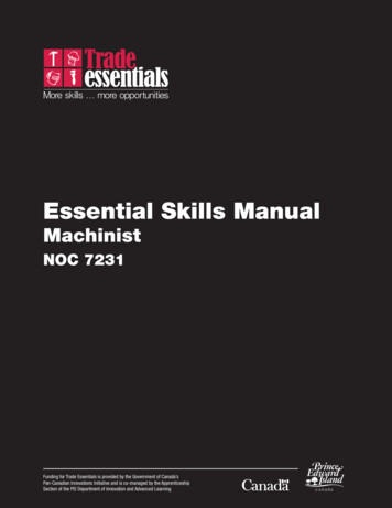
Centerdrill DimensionsSTANDARD 60 CENTERDRILL26SizeBody Dia(A)Drill Dia(D)Drill Length(C)OAL(L)001/80.0250.0301 1/801/81/320.0381 1/811/83/643/641 1/423/165/645/641 7/831/47/647/64245/161/81/82 1/857/163/163/162 3/461/27/327/32375/81/41/43 1/483/45/165/163 1/2MACHINIST’S CNC REFERENCE GUIDE
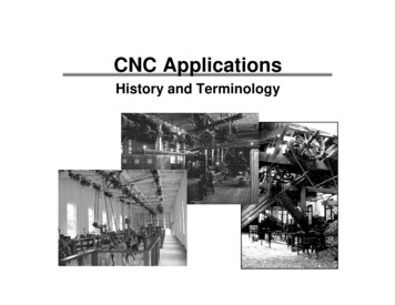
Drill Point Depth & CountersinkDiameter FormulasTo calculate drill tip depth for a chamfer diameter,or drill point depth for a required drilling depth:Drill PointAngle (DPA)Factor60 0.866 x Dia. Point Depth82 0.575 x Dia. Point Depth90 0.500 x Dia. Point Depth118 0.300 x Dia. Point Depth120 0.288 x Dia. Point Depth135 0.207 x Dia. Point DepthExample: To calculate for a 118-degree drill tip depth, multiply the dia. by 0.3i.e., 0.250 drill diameter x .3 0.075 drill tip depthMACHINIST’S CNC REFERENCE GUIDE27
Degree FormulasCONVERT MINUTES OF A DEGREE TO A DECIMAL:Divide minutes by 60degree minutes to convert:30 42'divide minutes by 60:42 60 0.7bring down degrees:30.7 CONVERT MINUTES AND SECONDS TO DECIMAL:Divide seconds, then minutes by 60degree minutes and seconds to convert:divide seconds by 60:divide decimal minutes by 60:bring down degrees:30 41' 15"15 60 0.2541.25 60 0.687530.6875 CONVERT A DECIMAL DEGREE TO MINUTES:Multiply decimal by 60decimal degree to convert:multiply decimal degree by 60:bring down degrees:30.7 0.7 x 60 42'30 42'CONVERT DECIMAL TO MINUTES AND SECONDS:Multiply decimal by 60decimal degree to convert:multiply the degree decimal by 60:multiply decimal minutes by 60:bring down degrees:30.6875 0.6875 x 60 41.25'0.25 x 60 15"30 41' 15"28MACHINIST’S CNC REFERENCE GUIDE
29MACHINIST’S CNC REFERENCE GUIDE
MACHINIST’S CNC REFERENCE GUIDE30
31MACHINIST’S CNC REFERENCE GUIDE
MACHINIST’S CNC REFERENCE GUIDE32
33MACHINIST’S CNC REFERENCE GUIDE
MACHINIST’S CNC REFERENCE GUIDE34
35MACHINIST’S CNC REFERENCE GUIDE
MACHINIST’S CNC REFERENCE GUIDE36
37MACHINIST’S CNC REFERENCE GUIDE
Haas Automation, Inc. USA2800 Sturgis Road, Oxnard, CA 93030P. 800-331-6746 I www.HaasCNC.comHaas Automation, EuropeMercuriusstraat 28, B-1930Zaventem, BelgiumP. 32-2-522 99 05 I www.HaasCNC.comHaas Automation, AsiaNo. 96 Yi Wei Road, Building 67Waigaoqiao F.T.Z., Shanghai, 200131, P.R.CP. 86-21-3861 6666 I www.HaasCNC.comThis book is copyrighted material. 2018 by Haas Automation, Inc., USA. All rights reserved.May not be reproduced without written permission from publisher.Extra copies available by contacting your local HFO.
This book is copyrighted material. 2018 by Haas Automation, Inc., USA. All rights reserved.May not be reproduced without written permission from publisher.Extra copies available by contacting your local HFO.Haas Automation, Inc. USA2800 Sturgis Road, Oxnard, CA 93030P. 800-331-6746 I www.HaasCNC.comHaas Automation, EuropeMercuriusstraat 28, B-1930Zaventem, BelgiumP. 32-2-522 99 05 I www.HaasCNC.comHaas Automation, AsiaNo. 96 Yi Wei Road, Building 67Waigaoqiao F.T.Z., Shanghai, 200131, P.R.CP. 86-21-3861 6666 I www.HaasCNC.com
MACHINIST S CNC REFERENCE GUIDE 3 DeCimal equivalenT CharT.0995 – .2969 Decimal DrillTap Equiv. Size mm Sizes.099539 2.5