Transcription
Router TableRead This Important Safety NoticeTo prevent accidents, keep safety in mind while you work. Use the safety guardsinstalled on power equipment; they are for your protection.When working on power equipment, keep fingers away from saw blades,wear safety goggles to prevent injuries from flying wood chips and sawdust, wearhearing protection and consider installing a dust vacuum to reduce the amount of airborne sawdust in your woodshop.Don’t wear loose clothing, such as neckties or shirts with loose sleeves, orjewelry, such as rings, necklaces or bracelets, when working on power equipment. Tieback long hair to prevent it from getting caught in your equipment.People who are sensitive to certain chemicals should check the chemical content of any product before using it.Due to the variability of local conditions, construction materials, skill levels,etc., neither the author nor Popular Woodworking Books assumes any responsibilityfor any accidents, injuries, damages or other losses incurred resulting from the material presented in this book.The authors and editors who compiled this book have tried to make the contents as accurate and correct as possible. Plans, illustrations, photographs and texthave been carefully checked. All instructions, plans and projects should be carefullyread, studied and understood before beginning construction.Prices listed for supplies and equipment were current at the time of publication and are subject to change.Metric Conversion Chartto converttomultiply byInches. . . . . . . . . . . . . . . . . Centimeters. . . . . . . . . . . . . . . . . . 2.54Centimeters. . . . . . . . . . . . . . Inches . . . . . . . . . . . . . . . . . . . . . 0.4Feet. . . . . . . . . . . . . . . . . . . Centimeters. . . . . . . . . . . . . . . . . . 30.5Centimeters. . . . . . . . . . . . . . . Feet. . . . . . . . . . . . . . . . . . . . . . 0.03Yards. . . . . . . . . . . . . . . . . . . . Meters . . . . . . . . . . . . . . . . . . . . . 0.9Meters. . . . . . . . . . . . . . . . . . . Yards. . . . . . . . . . . . . . . . . . . . . . 1.1
router tableThis router table design is adown and I'm ready to go. It has proven itscomposite of ideas I’ve seen and used over thedurability as I've used it for the past four years.years. What sets this router table apart fromI've added detailed plans and instructionsthe others is the router carriage lift mecha-showing how to make the router carriage/liftnism. It holds the router and controls the up-and the table.and-down adjustment without having to standA few weeks ago I looked up, in my ga-on your head or lift the whole top, carriagerage, and saw a bunch of 1 4 8' yellow pineand router to change bits. All I need to do isboards just collecting dust. (I recently movedopen the top (it's hinged on the back), grabinto this house and learned that this woodmy wrenches and go to it. I then flip the tophas been in the garage for about 12 years.) Itwas my favorite price (free) and it’s definitelydry. So, this new router table has a raisedpanel back and sides and matches my rollingtool chest (see Building the Perfect Tool Chest,project 6) that is made from old pallets. Thehardware for this router table is available atany home improvement center or hardwarestore. The top and insert are available from amanufacturer (I've named the supplier in theparts list), but I’ve included the materials you’dneed to make your own top.With a router table, I recommend usinga 3-hp router. It makes it easier to use largecutters, and the final cuts are smoother andcleaner than using a smaller-horsepower router.This router table features two dust-collection connections — one at the fence and onein the bottom of the table. This 4"-diameterbottom connection will pull air through thefront vent slots, helping to keep the router
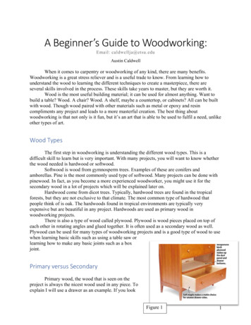
The finished router table looks handsome and isa friendly-looking woodshop tool. The castors arethe last things to be installed.cool and forcing the dust and chips into thedust collector. The collector at the fence picksup all the dust and chips thrown from thecutterhead. (This is how shapers are vented incabinet shops.) I've found it to be wonderfullyeffective on this router table.Things happen fast on a router table.The router is spinning about 20,000 rpm.None of us can think that fast, let alone reactthat quickly. Whenever I'm making a setupon the router table, I run through my mentalchecklist. Is the collet nut tight and the routerbit secure? Is the fence set correctly and tightened down? Are other attachments securely inplace? Then I run through it one more time— check twice before powering up.I've removed the two inner tops so you can see what the inside should look whenthe table is completed. The electric is easily routed along the top pullout spacerand behind the pullout. The inner tops will keep dust out of the pullout cavities.Let's get to building this router table!
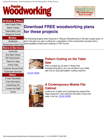
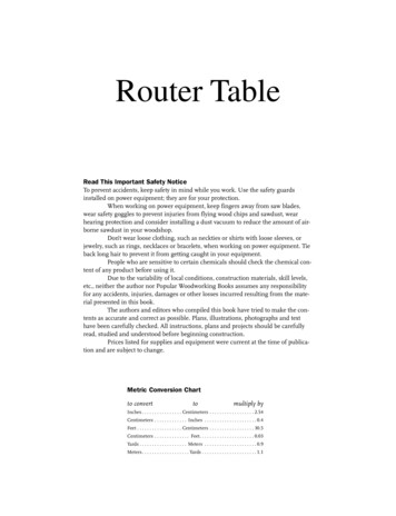
Lower center drawer configurationnot to scaleTop A18"24"1 8"9" x 14" insertHomemade woodenor storeboughtknobs (6)32"3 4"- wide by3 8"- deep groove36"2"PulloutSpacer G (4)Front/BackRail D (4)11 2"Side RailB (4)111 4"Inner topW (2)Shelf Q8"61 4"PulloutFront T (2)18"Back Panel E4"2"61 4"11 2"3 4"24"Side Panel C (2)DrawerFront U10"Dust collectorhose331 2"Shelf QLeg Part A (8)91 2"Foot Block F (4)3"24" 3"3"16"3"
ABCDEFGHJKLMNPQ842414422621122leg partsside railsside panelsfront and back railsback panelfoot blockspullout spacerspullout sidespullout backspullout shelvesdrawer sidesdrawer backdrawer bottominner-box sidesinner-box shelvespinepinepinepinepinepinescrap oodplywoodRSTUVWXY12211213inner-box backinner-box railspullout frontsdrawer frontvent panelinner topstopcleat blanksplywoodplywoodpinepinepineplywoodMDFpine3 43 41 23 41 21 2 421 43 43 43 43 43 43 43 43 43 43 43 43 43 43 411 23 19)(19)(19)(19)(19)(19)(19)(19)(19)(38)(19)33161 2 W3241 2 W21 421 )(229)(254)(521)(mm)1 33 218181 2 H26181 2 H91 2201 2171 2 H171 2 H171 4(851)(457)(470)(660)(470)(241)(521)18 D(445)41 4(445)41 4(438)91 4 H14 D (356)9H81 4 W (210)1014 D (356)201 224(610)10(254) 193 4 (502)10(254) 24(610)21 4(57) 10(254)61 4(159) 18(457)111 2 W (292) 10 H (254)111 2 W (292) 8 H(203)81 2(216) 201 2 (521)24(610) 36(914)3 4(19) ches (millimeters)partQuantityReferencem at e r i a l s l i s t45 miter one long edge, glue 2 parts to make 1 leg1" tenon both ends1" tenon both endsfit height to drawer opening w/part sitting on bottomfit width to drawer openingeach has one 4"-diameter hole for dust collector hosetrim to fittrim to fittrim to fit2 pieces of 3 4 MDF sandwiched togethercut cleats to length as neededHar dwar e2sets 18" (460mm) full-extension drawer slides43" swivel casters (two with locks)311 4" (32mm) wooden knobs111 2" (38mm) x 30" continous hinge2duplex electrical boxes1duplex socket1110V on/off switch1outlet cover plate1switch cover plate13 8"(10mm) x 9" (229mm) x 14" (356mm) MDF or plywood (for top insert)11 4"(6mm) x 12" (305mm) x 12" (305mm) tempered hardboard (for round plates in the top insert)Detail of Inner Box Shelves10"Back lineof drawer4"-dia. hole31 2" from centerof hole to back edgeof inner box shelvesInner boxshelf Q (2)193 4"
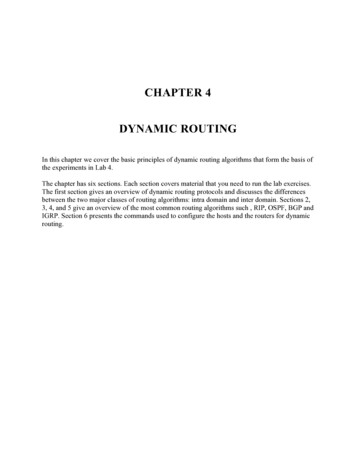
XBGJRSPQWHDVTCTUKFNLDA
the cabinet1Cut the lumber to rough lengths for the legs, rails and panels.Then take the lightest pass you can over your jointer to cleanup one face of each board. Then run each piece through yourplaner, again making a cut just deep enough to clean up theboards. The original thickness of the boards was 3 4" and the finalfinished out at 11 16"2Joint one edge of each of the panelboards, then cut the other edge onthe table saw. Joint this saw-cut edgeto clean it up for the glue joint.
34Glue up the panels first so the glue can be drying while you work on the legAlign the pieces and clamp them together. Be sure to have clamps on oppo-parts and rails.site sides of the panel for even clamping pressure.65Cut the rails to length. Be sure to allow for the 1" tenons. Notice the flipperWhen I rotate the part end-for-end, the flipper will drop down. I then butt theon my stop. I flip it up and slide the part under the flipper. This makes the cutpart against it and make the final-length cut.about 1 4" longer than the final length.For the longer-length leg parts, I7squared up one end .
8. then I slid this squared along the saw's fence(which has been set to the finished-length cut ofthe leg part) and made the final cut. This is a safecut because the sled supports the leg part as itrides along the fence.910Cut the mortises using a brad-point drill bit. I used a mortising jig that I madefor The Best Jigs & Fixtures for Your Woodshop, project No. 25, page 86.11Lay all the leg parts against a carpenter's square and clamp them together.By setting my drill press at its highest rotating setting (about 2,500 rpm), I'mMark the locations of the mortises.able to make a cleanly-cut mortise. Nice!
1312Yes, I'm using my original router table to cut the grooves for the raised panels. It's simply aThen cut the panel grooves in the rails. These run the entirematter of connecting the mortises. Lower the leg part so the router bit is in the mortise andlength of the parts.cut until you come to the other mortise. Remember, no grooves in the top and bottom frontrails and front leg parts.1415I used the same bit that I used to cut the grooves to cut the tenon faces . and edges.1617Now you can start working on the panels. Cut them to size and level the facesAfter cutting the panel bevels, cut the 45 bevels on the leg parts. Be sure tousing a hand plane and a random-orbital sander. To "raise" the panels, usemake 4 right-handed and 4 left-handed parts!your table saw. Set the blade angle so it finishes the bevel about 11 4" from theedge of the panel while leaving the edge about10thick.
18 a18 b18 cPair the leg parts and lay them out with the sharp edges of the bevels touching (18a). Run a piece of masking tape along the joint. Flip this assembly over andapply glue to the bevels (18b). Then fold the assembly. Make sure the leg parts form a square and let the glue dry (18c).Glue the foot blocks in place and assemble the19front and back sections. Lay out the parts on a flatsurface so the assembly will not have a twist. Sightalong the tops of the legs and make sure they areparallel with each other. That means the assemblyis flat.20After the glue is dry, glue the frontand back assemblies together. Thecabinet is now assembled!11
the pullouts and drawer12Cut out the pullout parts. Arrange your bits on the shelves. These are the larg-I drilled the rest of the shelves with two rows of holes spaced fairly evenly, justest cutter I have and they all fit on one shelf. I marked the hole locations andusing my eye to gauge the distance between holes. I drilled three shelves withdrilled them about halfway through the shelf.1 2"holes and the other three with 1 4" holes. I ended up with ninety holes total— more than enough for now and the future.361 4"17 3 8"Screw the pullout parts together. I made the right-handed pullout for my routerbits with 1 4" shanks the left-handed pullout for my 1 2" bits.1218"
Glue up the pullout spacers. Use whatever scraps you have4handy. Some of mine are made of plywood and some are madeof leftover pine. So far, I've spent no money for materials. All thiswood is leftover from other projects.56IAfter the glue has dried, machine the pullout spaces to their final dimensions and cut them to length. The spacers span the panels and are glued to the legs only.Locate them at the bottoms of the top rails and at the top of the bottom rails. Yeah, that's right. After the glue has dried, draw lines on the spacers perpendicularto the front rails. These are the center lines for the drawer sides. Remember to set the slides 3 4" back from the front face of the cabinet. Drill pilot holes and install the screws to attach the slides to the spacers.7Measure the distance between center lines on the spacers. Transfer thisdistance to the pullouts, draw centerlines on the pullout sides and attachthe drawer slides to the pullouts. Iallowed a 1 4" clearance between thetop rail and the top of the pulloutand the same at the bottom. Usingtwo slides on one side of a pulloutis a bit unusual, but it works great.However, if the pullout doesn't workperfectly the first time, you can tweakthe drawer slides a bit by removingall but the front screws on the spacerslides. Run the pullout into thecabinet about three-quarter. This willallow the spacer slides to align withthe slides on the pullout. Replacethe screws, drilling new pilot holes ifnecessary.13
89Center the box inside the cabinet. Attach it to the cabinet rails using screws.This installation will make the cabinet solid.Now cut out the parts for the inner box. Cut a 4"-diameter hole in the top shelf.This will accept the lower dust collector hose. (Yes, I still need to cut the hole.I forgot to do it before assembly!) I glued and screwed them together for positive holding strength. This box will look like a cabinet when it's done. The backruns the full length top to bottom and the front has top and bottom rails.1021 4"10"24"When locating the inner box inside the cabinet, the top of the bottom shelf ofthe inner box should be 1 16" proud of the top of bottom front rail of the cabinet. The drawer bottom will slide on this shelf without marring the front rail.10"191 4"21 4"111 2"14
1112Cut out the drawer parts. First, fit the drawer bottom into the drawer opening in the box. Trim asneeded so the bottom slides smoothly in and out.Now, put the bottom in the opening and fit the sides to thespace. Fit each side as there could be slight differences in thedrawer opening. Finally, assemble the drawer. Attach the sidesto the back, then center this assembly on the bottom. The sidesshould be about 1 8" in from the side edges of the bottom.13Apply some paste wax to the edges of the bottom and to the top edges of the sides. The drawershould slide smoothly in and out with minimal effort. Yes, you could use mechanical slides on thisdrawer if you like.93 4"91 4"10"14"111 2"15
1415Glue cleats to the pullout shelves, to the sides of the top space and to theCut out the drawer front, pullout fronts and the vent panel. Fit them to the frontsides of the drawer (I haven't glued these in place yet).of the router table, leaving about 3 32" space between all these parts. Then cutthe vents in the vent panel. Here, I am using my old router table to plunge-cutthe vent slots.16Glued the vent panel to the bottom ofthe top rail. Drill oversized holes in theside cleat and install one screw througheach of the cleats. The panel is free tomove with the seasons because thescrews will move in the oversized holes.16
17Use double-sided tape, applied to the front edgesof the drawer sides and bottom, to hold the drawerfront in place. Remove the drawer, glue the front tothe front edge of the drawer bottom install screwsthrough over-sized holes in the glue blacks.18Attach the pullout fronts using the same methodas you did for the drawer front. Glue the fronts tothe front edges of the sides. Install screws throughoversized hole in the cleats.Attach the knobs to the pullouts and the drawerfronts at locations that are convenient for yourreach. This completes the assembly of the routertable, inner box, pullouts and lower drawer.ro u t e r s17
the router carriageI'm not a mechanical genius by any means, but thisbest part is the fact that you only need to open the toprouter carriage is a very efficient method of holding theto change cutters. The router stays put in its collar androuter solidly and adjusting the height of the cutter. Theyou're ready to start routing in a about a minute.12Cut out three collars for the router collar assembly. In each collar, cut a holeIf your router has those little tabs on its body like mine does, you'll need to cutlarger (add 1 16" to the diameter) than the diameter of your router's body.out for those so the collar will slip on the router's body smoothly.34To hold the three collar pieces in alignment, I used my router as a form. UseCut the collar to shape using your table saw or band saw. Then stand the col-enough glue to hold the parts together but keep the glue away from the innerlar on edge and drill a 3 8"-diameter hole for the bolt.edges of the circle cutout if you can. If a little glue does stick to your router'sbody, simply pop off the dried glue with a chisel.18
router table carriageMDFMDFMDFMDFMDFMDFMDFMDF3 43 43 43 43 43 43 43 4(mm)(19)(19)(19)(19)(19)(19)(19)(19)5511 2731 2761 91 471171171 410commentsdovetail keepersdovetail keepersdovetailed guidesinner sidesbracescarriage deck platecollar blankstop ssQuantityinches (millimeters)Referencem at e r i a l s l i s t(254) 10 bevel one long edge(235) 10 bevel one long edge(178) 10 bevel two long edges(279)(178)(279)(184)(254)Har dwar eLockwasher (3)FlatwasherHexnut13 8"-16 x 12" (10mm x 300mm) threaded rod53 8"-16 (10mm) hex nuts33 8"-16 (10mm) flat washers33 8"-16 (10mm) lock washers23 8"-16 (10mm) T-nuts13 8"-16 x 4" (10mm x 100mm) hex-head boltTopbracket HAttach thishardware tohex-head bolt.T-nutDovetailkeeper B (2)Dovetailkeeper A (2)Hex-headboltCollarG (3)Carriage deckplate FOne T-nut is installedon underside ofcarriage deck plate.BracesE (2)Dovetailedguide C (2)Inner box sideInnerside D (2)Threadedrod19
56In the deck plate, center and cut a hole that is 1 2" larger in diameter than yourAttach the collar assembly to the carriage box, centering it over the oversizedrouter's body. Assemble the box. Then attach the dovetailed guides, centeringhole in the deck plate.them on the inner side parts. Make sure they are square to the inner sides.78Drill a hole that is large enough to accept the body of the T-nuts. This holeSlide the assembled router carriage into the top of the inner cabinet. Hold theruns through the collar and on through the deck plate. This photo shows thattabletop in place and center the hole in the tabletop insert with the hole in thethe holes need to be aligned perfectly. Then install the T-nuts; one in the bot-carriage. Mark the underside of the top to locate it on the router table.tom of the deck plate and one in the top of the collar assembly. The T-nuts willbe subjects to both clockwise and counter-clockwise twisting of the threadedrod, so I drilled three holes in the collars of the T-nuts and secured each nut inplace with three, No. 6 3 4" sheet metal screws.20
9Remove the top and install the longer dovetailkeepers, attaching them to the sides of the innerbox. Install one screw in the keepers, make surethe keepers align with the dovetailed guides andinstall a second screw.10Now install the shorter dovetail keepers. The topbracket will be installed on the top of these keepers, so they are 3 4" shorter than the other twokeepers. Push the keepers snugly against thedovetailed guides, then install two screws. Notethe spacers on the keeper on the left. The keepersneed to be firmly against the body of the carriage,so some adjustments may be necessary.11Remove the carriage and install a screw in the bottom of each keeper.21
1213Slide the carriage into the inner box. It should require a little effort to push itDrop a pencil (be sure it's long enough!) through the T-nuts and make a markinto place. When the carriage is adjusted up and down, the threaded rod willon the shelf of the inner box. Remove the carriage and drill a 1 2"-diameter holehave plenty of torque to move it. Again, you want the carriage to be solidly inat this center-marked location. The threaded rod will protrude through thisplace, so lots of friction isn't a bad thing in this case.hole about 1".1415Loosen the screws holding the collar in place. Start the threaded rod in theWhen the rod reaches the bottom T-nut, it's likely you'll need to finesse it intoT-nut.that bottom nut. The odds of the two nut's threads lining up perfectly are slim.Move the collar up slightly until the rod starts into the bottom nut.22c h a pte ro n e
16 aI chucked the rod into my drill. I hand-tightenedit. You don't want to mess up the threads at thetop of the rod. This will make the rod insertion goquickly. If you want to continue hand-screwing therod in place, that's fine.To determine how far to install the rod, removethe carriage (yes, once again!) and install yourrouter in the carriage. (I slid my router in until theplastic housing at the top of my router bottomedout against the bottom of the collar.) Then tightenthe collar with the hex bolt hardware. The routershould be rock solid in the carriage. Reinstall thecarriage.You'll need to experiment a little here. My "rule"was to raise the carriage until the top of the colletwas flush with the tabletop. You can determine thisby raising the carriage until the top of the collet is11 4" or 11 2" above the top edge of the inner box.Put a spacer under the carriage to hold it at thisheight.Now turn two nuts onto the rod about 2" down16 band add a flat washer. Screw the rod in until justbefore the nuts touch the T-nut.Tighten the screws that hold the collar in place.Try turning the rod. If it is hard to turn, run it up anddown and few times until it turns easier. If the rodwon't turn without undo force, loosen the collarscrews a little until the rod turns. You may need toadd thin spacers between the collar and the deckplate. Use some old playing cards. Be sure to addthem all around the bottom of the collar so therouter is square to the tabletop. You don't want therod to turn freely. It needs to have some resistanceto turning.Note that you may need to cut a notch in the topof the drawer to clear the threaded rod that is protruding through the inner box shelf.17Wow, now that that's done, hold the top bracket inplace. Mark where the threaded rod will come upthrough the bracket. Drill a 1 2"-diameter hole in thebracket and install the bracket. It should be flushwith the top edge of the sides of the inner box, orslightly below as shown in the photo.ro u t e r s23
Screw the bracket in place through the tops of thedovetail keepers. Then install screws through thesides of the inner box. This bracket is the anchorfor the height adjustment, so it needs to be solid.Remember those two nuts and flat washer onthe rod? Run them up until the flat washer justkisses the bottom of the bracket. If your top is 11 4"thick, you should have no more than 11 8" of rodshowing. If there is more, run the rod down until itreaches this measurement. Now, tighten the twonuts against each other to lock them in place.Install a flat washer on the rod and two morenuts. Tighten the nuts until they touch the flatwasher, then back them off about a half turn. Tighten them against each other. Here's the test — takea wrench, put it on the top nut and turn. The carriage should start moving up or down. Turn clockwise to raise, counter-clockwise to lower. Becausethe rod has 16 threads-per-inch, each full turn ofthe wrench will raise or lower the carriage a 1 16". Iuse a dedicated ratchet wrench for the height adjustment. I keep in the drawer of the router table.Back to the top. Cut the hinge to thelength of the router table (it shouldbe 30"!). I clamped a straightedgealong the mark I made earlier. Centerthe hinge and push it snug againstthe straightedge. Install all of thescrews.19Put the top on the table and installthe screws. A continuous hinge haslots of holding power, so the top will20stay in place for years to come.24c h a pte ro n e18
the electric1Trace around the electrical boxes. Drill starterholes for your jig saw.2Make the cutouts.The right top photo shows the electrical hardware you'll need. Remove theknockouts at both ends of the left box and one from the right box. Install theclamp connectors in the knockouts. Run one end of the electrical cord through3the far left clamp connector. Cut 10" of electrical cord and run it through theother two clamp connectors. Strip back about 4 or 5" of the outer cord insulation from the end of the long cord and the two ends of the short cord, separatethe wires, strip insulation from the ends of each wire.Attach the two black wires in the left box to the switch screw connectors.Wire-nut the two white wires together in the switch box. Attach the two greenwires to the green screw on the switch. Attach the black wire to the brassscrew connector and the white wire to the steel screw connector on the plug.Attach the green wire to the green screw on the plug. Your connections shouldlook like the lower right photo. Push the stuff into the boxes, screw the switchand outlet in place and attach the covers.Attach a three-prong plug to the other end of the long cord and you're goodto go.You'll need about 10' of No.12, braided 3-wire cord and a 3-prong, 110V plug. The black wire is hot, the white wire is neutral and the green wire is ground. Theswitch opens and closes the path of the current passing through the hot black wire, thus controlling the current flow to the outlet.ro u t e r s25
the fence12Glue two pieces of wood or, in my case, particle board, together to make theHey, this is the first job for your new router table! Setup a straightedge andfence. Then attach the fence cleat to the fence, making sure the assembly isrout two grooves in the fence.square.2"311/4"Knob11/4" x 11/4" x 2"3/4"Fence bracket17/8"Pivot block11/4" x 17/8"x 23/4"two flat washer and two T-nuts. To install the T-nuts in the knob,drill a stopped-hole large enough to fit the entire nut. Then drillstopped hole.26c h a pte ro n e3/8"flat washer31/2" x 3/8"- 16carriage bolthold-down clamps are no exception. All you need are two bolts,knob is turned, the T-nut pulls tightly against the bottom of the16 T-nutRouter table topBecause I'm cheap (or frugal), I make a lot of my fittings. Thea through-hole just large enough to clear the nut's body. As the3/8"-23/4"
45The dust hood for the fence is made from three pieces of MDF. Cut a hole in the hood to fit your dust collector or shop vacuum hose. The front piece is cut witha 45 bevel on both long edges. Cut a 45 angle to fit the end pieces to the front piece. You are now ready to start routing!Fence11/2" x 4" x 36"Dust hood endx 3" x 4" (2)3/4"Dust hoodx 5" x 6"3/4"1/4-20 x 21/2threaded knob (4)Adjustable fence (2)3/4" x 4" x 18"1/ 4 "x 14" slot (2)Fence cleatx 4" x 36"3/4"1/4-20T-nut (4)ro u t e r s27
P.10 F&W-Cuting-Edge Router Tips &Tricks (RPS 04- -5 ) 175L Now you can start working on the panels. Cut them to size and level the faces using a hand plane and a random-o