Transcription
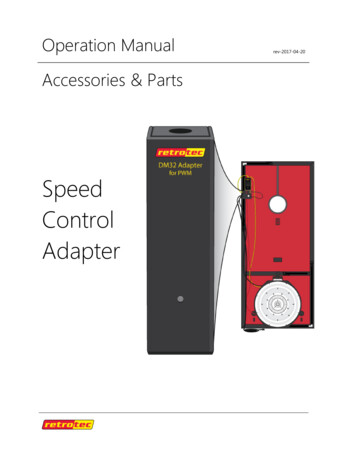
THE ENERGY CONSERVATORYSERIES BMINNEAPOLIS DUCT BLASTER OVERVIEW
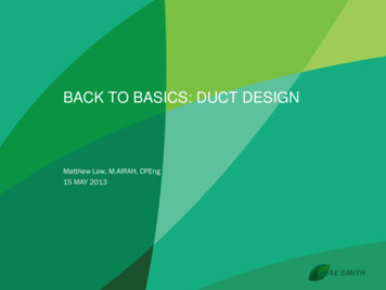
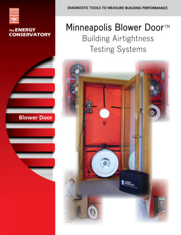
System ComponentsA standard Series B Minneapolis Duct Blaster KitInside the Duct Blaster accessory case is: Fan speed controller Foam flow conditioner Foam foot Sample roll of Premium DuctMask Register Sealing Tape Two trim pieces 30’ clear tubing Gauge board with clamp DG-1000 pressure and flowgauge kit Overview bookletSeries B calibrated fan includes: Ring 1 Ring 2 Ring 3 Flex duct Round and squaretransition pieces Nylon fan cover2
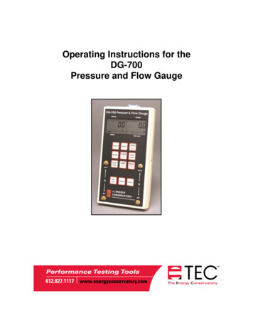
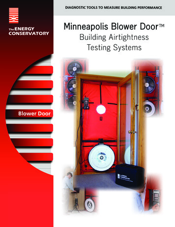
Duct Blaster FanThe Duct Blaster fan consists of a molded fan housingwith a variable speed motor. The Duct Blaster fan willmove up to 1,550 cubic feet of air per minute (CFM) at zeroback pressure (i.e. free air), and approximately 1,410 CFMagainst 50 Pascals (0.2 inches w.c.) of back pressure. Withthe flexible extension duct attached, the fan will move1,150 CFM (free air) and 1,025 CFM against 50 Pascals ofback pressure.Fan Flow RangesThe Duct Blaster fan can accurately measure flows between 2.4 and 1,500 CFM using aseries of four calibrated flow rings which are attached to the fan inlet.RingFlow Range in CFMMinimum Fan Pressure (Pa)Open (no flow ring)1,500 - 60025 PaRing 1800 - 22525 PaRing 2300 - 9025 PaRing 3125 - 103 PaRing 4 (optional)25 - 2.45 PaFan Speed ControllerEach system comes with one fan speed controller.Fan speed is adjusted using the adjustment knob onthe face of the fan speed controller or by connectingto the DG-1000 for Cruise Control.Flex DuctThe flexible extension duct consists of a12 foot long section of 10” round flexibleduct with one square and one roundblack plastic transition piece attached ateither end.3
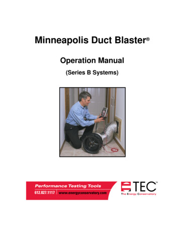
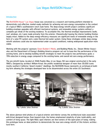
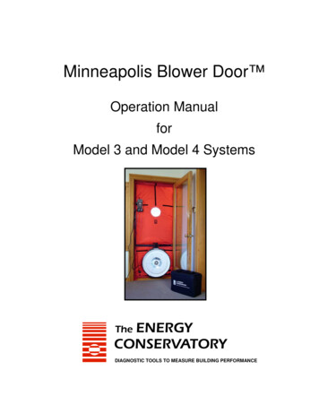
TEC Digital Pressure and Flow GaugeThe Minneapolis Duct Blaster System comes with a DG-1000 Pressure and Flow Gauge.This high accuracy differential pressure gauge measures the pressure differencebetween either of the input pressure taps and the corresponding reference pressuretap. Two separate measurement channels allow you to monitor the duct pressure andfan flow simultaneously during a test. The DG-1000 is packed with features to help youset up the gauge to perform a variety of tests related to duct testing and air handlermeasurements. In addition you are able to show leakage and flow values in a number ofmetrics.DG-1000 Pressure and Flow Gauge4
Series B Duct Blaster SpecificationsMaximum Flow1,550 CFM at free air (731 l/s, 2,633 m3/h)1,450 CFM at 25 Pa (684 l/s, 2,463 m3/h)1,410 CFM at 50 Pa (665 l/s, 2,395 m3/h)With flex duct attached1,150 CFM at free air (542 l/s, 1,954 m3/h)1,075 CFM at 25 Pa (507 l/s, 1,826 m3/h)1,025 CFM at 50 Pa (483 l/s, 1,741 m3/h)With flex duct, ring 1 and flow750 CFM at free air (354 l/s, 1,274 m3/h)conditioner (depressurization)725 CFM at 25 Pa (342 l/s, 1,231 m3/h)700 CFM at 50 Pa (330 l/s, 1,189 m3/h)Minimum Flow10 CFM with Ring 3 (5 l/s, 17 m3/h)2.4 CFM with Ring 4 (1.1 l/s, 4 m3/h)Fan Dimensions10 in. (25 cm) inlet diameter, 7 in (17.8 cm) lengthWeight7 lbs. (3.18 kg), 8.5 lbs. (3.86 kg) with 3 flow ringsFlow Accuracy /- 3% with DG-1000CalibrationMeets ASTM Standard E779, E1554, CGSB-149.10-M86,EN 3829, ATTMA Technical Standard 1, NFPA2001, ASHRAE 152, RESNET and USACEPower110V or 220VSpecifications subject to change without notice.Minneapolis Blower Door , TECTITE and DuctMask are trademarks of The Energy Conservatory. Duct Blaster , TrueFlow and FlowBlaster are registered trademarks of The Energy Conservatory. Stylized images of the Blower Door is also a Registered Trademark.5
ENERGY CONSERVATORY WARRANTYEXPRESS LIMITED WARRANTYSeller warrants that this product, under normal use and service as described in the operator’smanual, shall be free from defects in workmanship and material for a period of 24 months,or such shorter length of time as may be specified in the operator’s manual, from the date ofshipment to the Customer.LIMITATION OF WARRANTY AND LIABILITYThis limited warranty set forth above is subject to the following exclusions: With respect to any repair services rendered, Seller warrants that the parts repaired orreplaced will be free from defects in workmanship and material, under normal use, for aperiod of 90 days from the date of shipment to the Purchaser.Seller does not provide any warranty on finished goods manufactured by others. Only theoriginal manufacturer’s warranty applies.Unless specifically authorized in a separate writing, Seller makes no warrantywith respect to, and shall have no liability in connection with, any goods which areincorporated into other products or equipment by the Purchaser.All products returned under warranty shall be at the Purchaser’s risk of loss. ThePurchaser is responsible for all shipping charges to return the product to The EnergyConservatory. The Energy Conservatory will be responsible for return standard groundshipping charges. The Customer may request and pay for the added cost of expeditedreturn shipping.The foregoing warranty is in lieu of all other warranties and is subject to the conditionsand limitations stated herein. No other express or implied warranty IS PROVIDED, ANDTHE SELLER DISCLAIMS ANY IMPLIED WARRANTY OF FITNESS for particular purpose ormerchantability.The exclusive remedy of the purchaser FOR ANY BREACH OF WARRANTY shall be the returnof the product to the factory or designated location for repair or replacement, or, at the optionof The Energy Conservatory, refund of the purchase price.The Energy Conservatory’s maximum liability for any and all losses, injuries or damages(regardless of whether such claims are based on contract, negligence, strict liability or othertort) shall be the purchase price paid for the products. In no event shall the Seller be liablefor any special, incidental or consequential damages. The Energy Conservatory shall not beresponsible for installation, dismantling, reassembly or reinstallation costs or charges. Noaction, regardless of form, may be brought against the Seller more than one year after thecause of action has accrued.The Customer is deemed to have accepted the terms of this Limitation of Warranty andLiability, which contains the complete and exclusive limited warranty of the Seller. ThisLimitation of Warranty and Liability may not be amended or modified, nor may any of its termsbe waived except by a writing signed by an authorized representative of the Seller.TO ARRANGE A REPAIRPlease call The Energy Conservatory at 612-827-1117 before sending any product back forrepair or to inquire about warranty coverage. All products returned for repair should includean Equipment Service Form which is available at www.energyconservatory.com.6
Safety Information The Duct Blaster fan should only be connected to a properly installed and tested powersupply. In case of emergencies, disconnect the power cord from the AC power mains outlet.During installation, use the nearest readily accessible power outlet and keep all objects awayfrom interfering with access to the outlet.The Duct Blaster fan is a very powerful and potentially dangerous piece of equipment if notused and maintained properly. Carefully examine the fan before each use. If the fan housing, fanguards, blade, controller or cords become damaged, do not operate the fan until repairs havebeen made. Repairs should only be made by qualified TEC personnel.Disconnect the power plug from the Duct Blaster fan receptacle before making any adjustmentsto the fan motor, blades or electrical components.Keep people and pets away from the Duct Blaster fan when it is operating.Do not operate the Duct Blaster fan unattended. The operator should wear hearing protectionwhen in close proximity to the fan operating at high speed.Do not use ungrounded outlets or adapter plugs. Never remove or modify the grounding prong.Before connecting the speed controller to the fan, be sure the toggle switch of the controller isat zero and that the control knob is turned completely to the left (counterclockwise).Do not operate the Duct Blaster fan if the motor, controller or any of the electrical connectionsare wet.Recommended for indoor use only.The Duct Blaster fan motor is not a continuous duty motor and should not be run for extendedperiods of time (more than two hours at one time).If using a theatrical fogger with the Duct Blaster system, inject the fog stream toward theedge of the fan housing and not directly into the Duct Blaster fan motor. In addition, clean offany theatrical fog residue from the Duct Blaster fan motor and fan housing following the testprocedure. Use only non-corrosive fog.Be sure to remove all temporary register seals after completing the test procedure.When making repairs to the duct system with mastic or other curing sealants, allow the sealantto properly cure before conducting a duct leakage test to determine the effectiveness of yoursealing efforts. Refer to sealant installation instructions for proper curing times.Adjust all mechanical equipment (including the air handler fan) so that it does not turn on duringthe test.Be sure you have returned the mechanical equipment controls back to their original positionbefore leaving the building.Sealing leaks in a duct system should always be part of a larger total system diagnosticprocedure which includes examining total system air flow, system charge, airflow balancingand operation of vented combustion appliances. In addition, sealing air leaks (including ductleaks) in existing buildings can reduce the ventilation rate in those buildings. Existing ventilationrates and sources of indoor air pollutants should be considered by technicians beforelarge changes in ventilation rates are undertaken. Because of these complicated systemicinteractions between air sealing activities and occupant health and safety issues, it is highlyrecommended that technicians familiarize themselves with the Pressure Balancing/SystemPerformance and Combustion Safety test procedures before attempting to seal leaks in a ductsystem.Equipment safety measures may be compromised if the Duct Blaster fan is used in a mannerother than recommended in this document and the system operation manual.7
Software InformationThe Energy Conservatory (TEC) offers a variety of Windows-based programs. Theseprograms can be found and downloaded for free at software.energyconservatory.com.TEC also offers driver support for the DG-500, DG-700 and DG-1000. The driversare designed to work with Windows-based computers with the following operatingsystems: Windows 7 Windows 8 Windows 8.1 Windows 10The drivers are available as a Windows Update, and the DG-500 and DG-700 drivers canbe downloaded from TEC at software.energyconservatory.com.TEC also offers mobile apps for Apple and Android devices that can be found in the AppleApp Store or the Google Play Store.Instructional VideosThe Energy Conservatory (TEC) offers a variety of online instructional videos, including Minneapolis Blower Door Quick Guide Minneapolis Duct Blaster Quick Guide Field Calibration Checks for Gauges Pressure and Airflow Basics Exhaust Fan Flow Meter TECLOG TECTITE And many moreVisit energyconservatory.com/training to see more of TEC’s instructional videos.More Minneapolis Duct Blaster System GuidesAll Minneapolis Duct Blaster guides are available online atenergyconservatory.com/supportPlease refer to the guides listed below for further instructions. Minneapolis Duct Blaster Manual Duct Blaster Test Troubleshooting Using the DG-1000 with the Duct Blaster Test Results and Sample Forms2801 21st Avenue SouthSuite 160Minneapolis, Minnesota 55407 2021 The Energy ConservatoryUpdated October 2021Phone: (612) 827-1117Fax: (612) ory.com
The Minneapolis Duct Blaster System comes with a DG-1000 Pressure and Flow Gauge. This high accuracy differential pressure gauge measures the pressure difference between either of the inp