Transcription
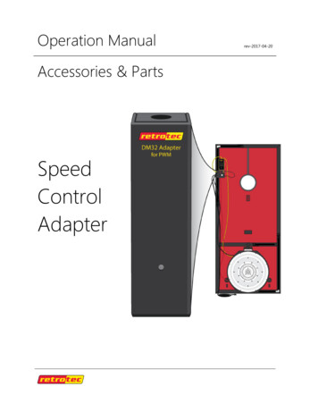
Operation ManualAccessories & PartsSpeedControlAdapterrev-2017-04-20
1. Overview . 32. What’s included . 43. Operation . 53.1Connect Adapter between gauge and TEC fan speed controller . 53.2Set the fan and range being used on the gauge . 53.3Connect Pressure Tubing for Minneapolis Model 3 . 63.4Connect Pressure Tubing for Minneapolis Model 4 . 63.5Connect Pressure Tubing for Minneapolis Duct Blaster . 84. Adapter Technical Details . 104.1Fan Compatibility. 104.2Gauge Compatibility . 104.3LED Power Status Indicator . 10Extra Features the DM32 gives your TEC DevicesPressurization testing no longer requires the use of an additional tube that is run to the other side of thecloth. DM32 takes care of this in software and always makes the correct decision.The True Flow Grid can be corrected in the gauge without using correction tables.Hole Flow enables you to measure the flow rate from any supply or into any exhaust device just using abox with a hole cut in it.Hold readings and convert to any units used worldwide without a calculator.Blower door can be used to measure air handler flow automatically. Since our Set Pressure can be anyvalue, simply measure the supply pressure. Set the pressure in the gauge to this pressure, and theblower door willl measure the air handler flow.Page 2 of 10 Retrotec 2017
1. OverviewNow you can use the newest and most modern gauge with features such as Touch Screen, two waycommunication with laptops locally or over the Internet, WiFi and advance FanTestic software.Fans manufactured by TEC (such as those used with the Minneapolis Duct Blaster or MinneapolisBlower Door Model 3 or 4) can be controlled by the Fan Speed control output on a Retrotec gaugeusing the Retrotec Model FN275 - Speed Control Adapter (for TEC fans). The fan speed control musthave the cruise input port which is indicated by the presence of an audio jack on the side.Figure 1: Control a TEC fan using the Retrotec gauge and fan control adapterPage 3 of 10 Retrotec 2017
2. What’s includedThe Adapter kit comes with both connectors needed – a short yellow Ethernet-style Speed ControlCable, and a short black cable with 3.5 mm audio connectors. The Speed Control Cable connects to theSpeed Control output on the top of the Retrotec gauge, and the black connector goes from the Adapterto the Minneapolis Fan Speed Control Cruise input port.The DM32 comes with a Tubing Accessory kit, so users will have the Retrotec color coded pressuretubes.Connecting the pressure ports to the TEC fan as described in this document will allow the Retrotecgauge to correctly calculate results, and allow the user to follow the testing procedures shown in theRetrotec QuickGuides.Page 4 of 10 Retrotec 2017
3. Operation3.1Connect Adapter between gauge and TEC fan speed controllerRetrotec-TEC Fan speed control Adapter is connected between the gauge and the TEC fan speedcontroller, in line with the Speed Control cable as shown in Figure 2: Attach Adapter inline betweengauge Speed Control Output and Minneapolis Fan Speed Control Cruise Input.Figure 2: Attach Adapter inline between gauge Speed Control Output and Minneapolis Fan Speed Control Cruise InputOnce connected, the Speed Control signal from the Retrotec gauge will control the fan. User can utilizethe Set Speed or Set Pressure functions, or any of the automated software solutions from Retrotec tocontrol the gauge, which will in turn drive the (non-Retrotec) fan.3.2Set the fan and range being used on the gaugeUser must be sure to select the fan on the gauge corresponding to the fan installed in the Blower Door.With the DM32, this is a matter of a few taps on the touchscreen, as shown in Figure 3.Figure 3: User must set the type of fan on the gauge to the TEC fan in usePage 5 of 10 Retrotec 2017
In order to use the color-coded pressure input ports, diagrams are provided indicating how to hook upeach of the TEC fans using the Retrotec color codes. Equivalent set up is shown for each model fan, andwhether the fan is being used for pressurizing or depressurizing.Once the pressure tubing is hooked up using the Retrotec color scheme, Retrotec QuickGuides andmanuals describing the various procedures encountered while using Blower Door equipment can befollowed without translation of the tubing color.When discussing Pressurize and Depressurize, the diagrams assume that the operator and the gauge areon the inside of the space being pressurized or depressurized. Another term for Depressurize is “Flowtowards Operator”, and for Pressurize is “Flow Away from Operator”.3.3Connect Pressure Tubing for Minneapolis Model 3 Figure 4: View of Retrotec gauge tubing when used with Model 3When pressurizing, the Retrotec gauge internally compensates for the back pressure on the non-selfreferenced fans such as the MN Model 3 using the induced pressure measured on Channel A betweenthe room and the outdoors, so only one tube needs to be run to the outdoors.Figure 5: Comparison of connections using a Retrotec gauge instead of the TEC gauge using Model 33.4Page 6 of 10 Retrotec 2017Connect Pressure Tubing for Minneapolis Model 4
Figure 6: View of Retrotec gauge tubing when used with Model 4In both Pressurize and Depressurize set ups with a Retrotec gauge, both yellow and green tubes go tothe brass taps on the Model 4 fan, for the later Model 4 fans with two pressure taps, which are selfreferencing. If the Model 4 fan you have has only one pressure tap, you must be passing the clear tubethrough the door panel as instructed by TEC. In that case, the yellow tube on the Retrotec gauge isreplacing the clear tube so the yellow tube will be wherever the clear tube was in your previous set up.It is important that both the yellow and green tube are used with the Retrotec gauge when the fan typeis chosen as Model 4, just as the TEC gauge requires both the red and clear tubes.There is no change in the tubing from gauge to fan when changing between pressurize and depressurize,the only difference is that the fan is taken out of the cloth, turned around and put back into the clothfacing the other way.Figure 7: Comparison of connections using a Retrotec gauge instead of the TEC gauge using Model 4Page 7 of 10 Retrotec 2017
3.5Connect Pressure Tubing for Minneapolis Duct Blaster Figure 8: View of Retrotec gauge tubing when used with Duct Blaster (no need for green in Pressurize)In both Pressurize and Depressurize set ups with a Retrotec gauge, the yellow tube goes to the brass tapon the Duct Blaster fan.When using the Retrotec gauge in a Depressurize setup, the Green tube goes to the plastic port on theFlow Conditioner which MUST be used when depressurizing and must include the piece of rigid foamwith holes that looks like a piece of packing material but is essential to allowing the Duct Blaster tomeasure in the depressurization direction accurately.Figure 9: Flow conditioner installed for Depressurize*Figure 10: Duct Blaster Flow conditioner plastic tap**Flow conditioner pictures courtesy of The Energy Conservatory, Inc.Page 8 of 10 Retrotec 2017
Figure 11: Comparison of connections using a Retrotec gauge instead of the TEC gauge using Duct BlasterNote that in Pressurize set up, the gauge green tube is not required as the Flow Conditioner will beremoved from the Duct Blaster.Page 9 of 10 Retrotec 2017
4. Adapter Technical Details4.1Fan CompatibilityThe Speed Control Adapter (for TEC fans) (Retrotec part number FN275) is designed to convert the fanspeed control output from Retrotec gauges to a Pulse Width Modulation (PWM) scheme required by thecruise input on TEC fan speed control unit.The Adapter thus works with any fans that use the TEC fan speed control unit, or a compatible PWMspeed control scheme.4.2Gauge CompatibilityThe Speed Control Adapter is designed to work with the fan speed control output from Retrotec gauges,including the DM32 and the DM-2. Given that DM-2 are reaching end of lifecycle, it would be prudentfor Speed Control Adapter users to use the DM32 to control their TEC fans.4.3LED Power Status IndicatorThe LED on the front indicates the status of power internal to the Adapter. The Adapter uses an AAbattery to supplement the power provided by the Speed Control Output. A green light when plugged inmeans that the Adapter battery has adequate charge.When the battery voltage falls to 5.4V, the red light will come on as a ‘low battery’ indication, meaningthe internal battery needs to be changed (9V battery).Battery life when used with the DM32 gauge is expected to be unlimited, since power from the batteryis only required when the fan is running at 90-100% speed.When used with a DM-2 gauge, the battery will need to be changed at regular intervals, since the DM-2speed control output needs more boosting.Page 10 of 10 Retrotec 2017
3.5 Connect Pressure Tubing for Minneapolis Duct Blaster Figure 8: View of Retrotec gauge tubing when used with Duct Blaster (no need for green in Pressurize) In both Pressurize and Depressurize