Transcription
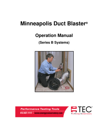
Minneapolis Duct Blaster Operation Manual(Series B Systems)
Minneapolis Duct Blaster Operation Manual(Series B Systems)The Energy Conservatory2801 21st Ave. S., Suite 160Minneapolis, MN 55407(612) 827-1117 (Ph)(612) 827-1051 (Fax)www.energyconservatory.comemail: info@energyconservatory.comMinneapolis Duct Blaster and TrueFlow Air Handler Flow Meter are registered trademarks of The EnergyConservatory, Inc. Minneapolis Blower Door, TECBLAST, Duct Mask and Automated Performance Testing(APT) System are trademarks of The Energy Conservatory, Inc.Windows and Microsoft Word are registered trademarks of Microsoft Corporation.
Manual Edition: July 2014 2014 by The Energy Conservatory. All rights reserved.ENERGY CONSERVATORY WARRANTYEXPRESS LIMITED WARRANTY:Seller warrants that this product, under normal use and service as described in the operator’s manual, shall be free from defects inworkmanship and material for a period of 24 months, or such shorter length of time as may be specified in the operator’s manual, from thedate of shipment to the Customer.LIMITATION OF WARRANTY AND LIABILITY:This limited warranty set forth above is subject to the following exclusions:a)b)c)d)With respect to any repair services rendered, Seller warrants that the parts repaired or replaced will be free from defects inworkmanship and material, under normal use, for a period of 90 days from the date of shipment to the Purchaser.Seller does not provide any warranty on finished goods manufactured by others. Only the original manufacturer’s warranty applies.Unless specifically authorized in a separate writing, Seller makes no warranty with respect to, and shall have no liability in connectionwith, any goods which are incorporated into other products or equipment by the Purchaser.All products returned under warranty shall be at the Purchaser’s risk of loss. The Purchaser is responsible for all shipping charges toreturn the product to The Energy Conservatory. The Energy Conservatory will be responsible for return standard ground shippingcharges. The Customer may request and pay for the added cost of expedited return shipping.The foregoing warranty is in lieu of all other warranties and is subject to the conditions and limitations stated herein. No other express orimplied warranty IS PROVIDED, AND THE SELLER DISCLAIMS ANY IMPLIED WARRANTY OF FITNESS for particular purpose ormerchantability.The exclusive remedy of the purchaser FOR ANY BREACH OF WARRANTY shall be the return of the product to the factory or designatedlocation for repair or replacement, or, at the option of The Energy Conservatory, refund of the purchase price.The Energy Conservatory’s maximum liability for any and all losses, injuries or damages (regardless of whether such claims are based oncontract, negligence, strict liability or other tort) shall be the purchase price paid for the products. In no event shall the Seller be liable for anyspecial, incidental or consequential damages. The Energy Conservatory shall not be responsible for installation, dismantling, reassembly orreinstallation costs or charges. No action, regardless of form, may be brought against the Seller more than one year after the cause of actionhas accrued.The Customer is deemed to have accepted the terms of this Limitation of Warranty and Liability, which contains the complete and exclusivelimited warranty of the Seller. This Limitation of Warranty and Liability may not be amended or modified, nor may any of its terms be waivedexcept by a writing signed by an authorized representative of the Seller.TO ARRANGE A REPAIR: Please call The Energy Conservatory at 612-827-1117 before sending any product back for repair or to inquireabout warranty coverage. All products returned for repair should include the reason for repair, a return shipping address, name and phonenumber of a contact person concerning this repair, and the purchase date of the equipment.
Table of ContentsSafety InformationEquipment Safety Instructions11Chapter 1Introduction to the Minneapolis Duct Blaster 2Chapter 2Duct Leakage Basics32.1 Why Is Duct Leakage Important?32.2 Where Does Duct Leakage Occur?32.3 How Much Can Energy Bills Be Reduced By Sealing Duct Leaks?42.4 Duct Leakage to the Outside42.5 Duct Leakage to the Inside5Chapter 3System Components3.1 Duct Blaster Fan3.1.a Determining Fan Flow and Using the Flow Rings:6673.2 Test Instrumentation (DG-700 Pressure and Fan Flow Gauge)83.3 Fan Speed Controller83.4 Flexible Extension Duct93.5 The Flow Conditioner93.6 Duct Blaster Carrying Case103.7 TECBLAST Duct Airtightness Test Software (Optional)103.7.a TECBLAST Features:10Chapter 4Prepare the Duct System and Building for Testing11Chapter 5Setting Up the Duct Blaster for Pressurization Testing125.1 Where to Install the Duct Blaster System?125.2 Connecting the Duct Blaster to the Duct System135.2.a Installing at a Central Return:5.2.b Installing at the Air Handler Cabinet:13145.3 The Gauge Mounting Board155.4 Gauge Tubing Connections for Pressurization Testing155.5 Selecting a Location to Measure Duct System Pressure165.5.a Insert the Pressure Probe:5.6 Tubing and Electrical Connections to the Fan5.6.a Connect Red Tubing to the Fan:5.6.b Electrical Connections:5.7 Fan Control Cable for Cruise ControlChapter 61617171717Conducting a Total Leakage Pressurization Test186.1 Final Preparations (Open a Door or Window to the Outside)196.2 Choosing the Test Pressure and Number of Test Readings196.2.a Test Pressure:6.2.b Number of Test Readings:1919
6.3 Total Leakage Test Procedures Using the DG-700206.4 Using the Can’t Reach Pressure Factors (One-Point Tests)236.4.a Potential Errors In One-Point CFM25 Estimate from Using the CRP Factors:236.5 Unable to Reach a Target Building Pressure During a Multi-Point Test?246.6 Before Leaving the Building24Chapter 7Conducting a Leakage to Outside Pressurization Test7.1 Final Preparations (Set Up Blower Door in Building)7.1.a Building Pressure Measurements:2526267.2 Choose the Test Pressure277.3 Leakage to Outside Test Procedures Using the DG-700277.4 What If You Can Not Pressurize the Building to the Test Pressure with the Blower Door Fan?297.5 What If You Can Not Pressurize the Duct System to the Same Pressure as the Building with theDuct Blaster Fan?307.6 Before Leaving the BuildingChapter 8Test Results8.1 Basic Duct Airtightness Test Results8.1.a Duct Leakage at 25 Pascals:8.1.b Normalizing Duct Leakage for the Size of the HVAC System and Building:8.1.c Leakage Areas:8.2 Additional Test Result Options (requires use of TECBLAST software)8.2.a Estimated System Efficiency Losses:8.2.b Duct Leakage Curve:Chapter 9Setting Up the Duct Blaster for Depressurization Testing313232323334343435369.1 Installing the Flow Conditioner and Flow Ring369.2 Where to Install the Duct Blaster System?379.3 Connecting the Duct Blaster to the Duct System379.4 Gauge Tubing Connections for Depressurization Testing379.5 Selecting a Location to Measure Duct System Pressure389.6 Tubing and Electrical Connections to the Fan389.6.a Connect Red Tubing to the Fan:9.6.b Connect Clear Tubing to the Round Transition Piece:9.6.c Electrical Connections:Chapter 10Conducting a Total Leakage Depressurization Test3838383910.1 Final Preparations (Open a Door or Window to the Outside)4010.2 Choosing the Test Pressure and Number of Test Readings4010.2.a Test Pressure:10.2.b Number of Test Readings:404010.3 Total Leakage Test Procedures Using the DG-7004110.4 Using the Can’t Reach Pressure Factors (One-Point Tests)4410.4.a Potential Errors In One-Point CFM25 Estimate from Using the CRP Factors:4510.5 Unable to Reach a Target Building Pressure During a Multi-Point Test?4510.6 Before Leaving the Building45
Chapter 11Conducting a Leakage to Outside Depressurization Test11.1 Final Preparations (Set Up Blower Door in Building)11.1.a Building Pressure Measurements:46474711.2 Choose the Test Pressure4811.3 Leakage to Outside Test Procedures Using the DG-7004811.4 If You Can Not Depressurize the Building to the Test Pressure with the Blower Door Fan?5011.5 If You Can Not Depressurize the Duct System to the Same Pressure as the Building with theDuct Blaster Fan?5111.6 Before Leaving the Building52Chapter 12Finding Duct Leaks5312.1 Using a Theatrical Fog Machine5312.2 Using a Handheld Smoke Puffer53Chapter 13Using the Duct Blaster as a Powered Capture Hood5413.1 Measuring Total System Air Flow (Pressure Matching Method)5413.2 Measuring Return Register and Exhaust Fan Flows5613.3 Measuring Supply Register Flows5713.4 The FlowBlaster Capture Hood Accessory58Chapter 14Pressure Balancing and System Performance Testing14.1 Testing for Pressure Imbalances Caused By Forced Air System Flows14.1.a14.1.b14.1.c14.1.dDominant Duct Leak Test:Master Suite Door Closure:All Interior Doors Closed:Room to Room Pressures:14.2 System Performance Testing14.2 a Total System Air Flow:14.2.b System Charge:14.2.c Airflow Balancing:Chapter 15Combustion Safety Testing595959606060616161616215.1 Overview6215.2 Test Procedures6315.2.a Measure Ambient CO Level in Building:15.2.b Survey of Combustion Appliances:15.2.c Survey of Exhaust Fans:15.2.d Measure Worst Case Fan Depressurization:15.2.e Spillage Test (natural draft and induced draft appliances):15.2.f Draft Test (natural draft appliances):15.2.g Carbon Monoxide Test:15.2.h Heat Exchanger Integrity Test (Forced Air Only):Chapter 16Appendix AUsing the Duct Blaster as a Blower DoorCalibration and Maintenance64646464666767676970A.1 Fan Calibration70A.2 Issues Affecting Fan Calibration71A.2.a Fan Flow Sensor and Motor Position:A.2.b Upstream Air Flow Conditions:7173
A.2.c Operating Under High Backpressure Conditions:A.3 Duct Blaster Fan Maintenance and SafetyA.3.a Maintenance Checks:A.3.b General Operational Notes and Tips:A.4 Calibration and Maintenance of Digital Pressure Gauges7374747474A.4.a Digital Gauge Calibration:A.4.b Digital Gauge Maintenance:7475A.5 Checking for Leaky Tubing76Appendix BFlow Conversion Table77Series B Duct Blaster (110V and 230V)77Appendix CSample Test Form79Appendix DTechnical Specifications81D.1 Specifications81Appendix EEstimating HVAC System Loss From Duct Airtightness Measurements82Appendix FUsing Optional Ring 482
Safety InformationSafety InformationEquipment Safety Instructions1.The Duct Blaster fan should only be connected to a properly installed and tested power supply. In case ofemergencies, disconnect the power cord from the AC power mains outlet. During installation, use thenearest readily accessible power outlet and keep all objects away from interfering with access to the outlet.2.The Duct Blaster fan is a very powerful and potentially dangerous piece of equipment if not used andmaintained properly. Carefully examine the fan before each use. If the fan housing, fan guards, blade,controller or cords become damaged, do not operate the fan until repairs have been made. Repairs shouldonly be made by qualified repair personnel.3.Disconnect the power plug from the Duct Blaster fan receptacle before making any adjustments to the fanmotor, blades or electrical components.4.Keep people and pets away from the Duct Blaster fan when it is operating.5.Do not operate the Duct Blaster fan unattended. The operator should wear hearing protection when in closeproximity to the fan operating at high speed.6.Do not use ungrounded outlets or adapter plugs. Never remove or modify the grounding prong.7.Before connecting the speed controller to the fan, be sure the toggle switch of the controller is at zero andthat the control knob is turned completely to the left (counterclockwise).8.Do not operate the Duct Blaster fan if the motor, controller or any of the electrical connections are wet.Recommended for indoor use only.9.The Duct Blaster fan motor is not a continuous duty motor and should not be run for extended periods oftime (more than 2 hours at one time).10. If using a theatrical fogger with the Duct Blaster system, inject the fog stream toward the edge of the fanhousing and not directly into the Duct Blaster fan motor. In addition, clean off any theatrical fog residuefrom the Duct Blaster fan motor and fan housing following the test procedure. Use only non-corrosive fog.11. Be sure to remove all temporary register seals after completing the test procedure.12. When making repairs to the duct system with mastic or other curing sealants, allow the sealant to properlycure before conducting a duct leakage test to determine the effectiveness of your sealing efforts. Refer tosealant installation instructions for proper curing times.13. Adjust all mechanical equipment (including the air handler fan) so that it does not turn on during the test.14. Be sure you have returned the mechanical equipment controls back to their original position before leavingthe building.15. Sealing leaks in a duct system should always be part of a larger total system diagnostic procedure whichincludes examining total system air flow, system charge, airflow balancing and operation of ventedcombustion appliances. In addition, sealing air leaks (including duct leaks) in existing buildings can reducethe ventilation rate in those buildings. Existing ventilation rates and sources of indoor air pollutants shouldbe considered by technicians before large changes in ventilation rates are undertaken. Because of thesecomplicated systemic interactions between air sealing activities and occupant health and safety issues, it ishighly recommended that technicians familiarize themselves with the Pressure Balancing/SystemPerformance and Combustion Safety test procedures listed in Chapters 14 and 15 before attempting to sealleaks in a duct system.16. Equipment safety measures may be compromised if the Duct Blaster fan is used in a manner other thanrecommended in this document and the system operation manual.1
Chapter 1Chapter 1Introduction to the Minneapolis Duct BlasterIntroduction to the Minneapolis Duct Blaster Air leakage in forced air duct systems is now recognized as a major source of energy waste in both new andexisting houses and commercial buildings. Research conducted by the Florida Solar Energy Center (FSEC),Advanced Energy Corporation (AEC), Proctor Engineering, Ecotope and other nationally recognized researchorganizations has shown that testing and sealing leaky distribution systems is one of the most cost-effectiveenergy improvements available in many houses and light commercial buildingsThe Minneapolis Duct Blaster is a calibrated air flow measurement system designed to test and document theairtightness of forced air duct systems. Airtightness measurements of duct systems are used for a variety ofpurposes including: Documenting and certifying compliance with building code or other construction standards requiringairtight duct systems.Troubleshooting comfort and performance complaints from building owners.Measuring and documenting the effectiveness of duct sealing activities.Estimating annual HVAC system losses from duct leakage.This manual describes how to measure duct airtightness using the Minneapolis Duct Blaster. Duct airtightness isdetermined by measuring the leakage rate of the duct system when it is subjected to a uniform test pressure bythe Duct Blaster fan. Duct airtightness test results are typically expressed in terms of cubic feet per minute (cfm)of leakage at a corresponding test pressure (e.g. 155 cfm at 25 Pascals). Duct airtightness test results can also beexpressed in terms of leakage areas (e.g. square inches of hole) or normalized leakage rates (e.g. measured ductleakage rate as a percent of total system air flow).A duct airtightness test is performed by first connecting the Duct Blaster system to the ductwork at either acentral return grille or at the air handler cabinet. After temporarily sealing off all intentional openings in the ductsystem (e.g. supply and return registers, and combustion or ventilation air inlets which are connected to the ductsystem), the Duct Blaster fan is used to pressurize or depressurize the entire duct system to a standard testpressure. For residential duct systems, 25 Pascals (0.10 inches w.c.) is the most commonly used test pressure.This test pressure has been adopted by most duct testing programs because research has shown that 25 Pascalsrepresents a typical operating pressure in many residential systems. The air flow needed from the Duct Blasterfan to generate the test pressure in the duct system is the measured leakage rate. Both the duct system pressureand the Duct Blaster fan air flow are measured by a calibrated digital pressure gauge.In addition to measuring duct airtightness, the Minneapolis Duct Blaster can be used as a powered flow hood toaccurately measure total air flow through the air handler, supply and return registers, exhaust fans and other airflow devices. The Duct Blaster can also be used as a small Blower Door to test the airtightness of small ortightly built houses.Note: The leakage rate of a duct system determined using the airtightness test procedures listed in this manualmay differ from the leakage rates occurring in the duct system under actual operating conditions. Whenconducting an airtightness test, all leaks in the ductwork are subjected to approximately the same pressure (i.e.the test pressure). Under actual operating conditions, pressures within the duct system vary considerably with thehighest pressure present near the air handler, and the lowest pressures present near the registers. Researchers areworking on developing additional test procedures which will provide duct leakage measurements under actualoperating conditions.2
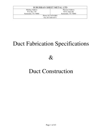
Chapter 2Chapter 2Duct Leakage BasicsDuct Leakage Basics2.1 Why Is Duct Leakage Important?Studies indicate that duct leakage can account for as much as 25% of total house energy loss, and in many caseshas a greater impact on energy use than air infiltration through the building shell. In many light commercialbuildings, duct leakage is often the single largest cause of performance and comfort problems.Here are just a few of the problems resulting from duct leakage: Leaks in the supply ductwork cause expensive conditioned air to be dumped directly outside or in the atticor crawlspace rather than delivered to the building.Leaks in the return ductwork pull unconditioned air directly into the HVAC system reducing both efficiencyand capacity. For example, if 10 percent of the return air for an air conditioning system is pulled from a hotattic, system efficiency and capacity are often reduced by as much as 30 percent.In humid climates, moist air being drawn into return leaks can overwhelm the dehumidification capacity ofair conditioning system causing buildings to feel clammy even when the system is operating.Duct leakage greatly increases the use of electric strip heaters in heat pumps during the heating season.Leaks in return ductwork draw air into the building from crawlspaces, garages and attics bringing with itdust, mold spores, insulation fibers and other contaminants.2.2 Where Does Duct Leakage Occur?Because the air leaking from ductwork is invisible, most duct leaks go unnoticed by homeowners and HVACcontractors. In addition, ducts are often installed in difficult to reach spots like attics and crawlspaces, or are"buried" inside building cavities making them even more difficult to find. And the hard to find leaks are usuallythe most important leaks to fix, because they are connected to a hot attic or humid crawlspace.Common Duct Leakage ProblemsReturn Leak Through Wall CavitySupply Leak at Take-Off Connection3
Chapter 2Duct Leakage BasicsDuct leaks can be caused by a variety of installation and equipment failures including: Poorly fitting joints and seams in the ductwork.Disconnected or partially disconnected boot connections.Holes in duct runs.Use of improperly sealed building cavities for supply or return ducts."Platform" return plenums which are connected to unsealed building cavities.Poor connections between room registers and register boots.Poorly fitting air handler doors, filter doors and air handler cabinets.Failed taped joints.The impact on a particular building will depend on the size of the duct leak, the location of the duct leak andwhether or not the leak is connected to the outside.2.3 How Much Can Energy Bills Be Reduced By Sealing Duct Leaks?Numerous studies conducted by nationally recognized research organizations has shown that testing and sealingleaky distribution systems is one of the most cost-effective energy improvements available in many houses. Asummary of 19 separate duct leakage studies indicates that the average annual energy savings potential in atypical home is around 17 percent.1A 1991 study in Florida found:2 Air conditioner use was decreased by an average of 17.2% in a sample of 46 houses where comprehensiveduct leakage diagnostics and sealing were performed.These houses saved an average of 110 per year on cooling bills at a cost of approximately 200 for repairs.Duct leaks also waste energy in heating climates. A study of 18 houses in Arkansas showed that a duct leakagerepair service saved 21.8% on heating bills by eliminating three-quarters of the duct leakage in the studyhouses.3 In addition to the energy savings, duct leakage repair improves homeowner comfort and reducescallbacks by allowing the HVAC system to work as designed.2.4 Duct Leakage to the OutsideDuct leakage to the outside has the largest impact on HVAC system performance. Duct leakage to the outsidecommonly results from leaky ductwork running through unconditioned zones (attics, crawlspaces or garages).Most of the duct leakage research studies referenced in this manual have been performed on houses whichcontain significant portions of the duct system in unconditioned zones. However, significant leakage to theoutside can also occur when all ductwork is located within the building envelope. In these cases, leaky ducts1 Neme, Chris et. al. 1999, "Energy Savings Potential From Addressing Residential Air Conditioner and HeatPump Installation Problems".2 Cummings, James et. al. 1991, "Investigation of Air Distribution System Leakage and its Impacts in CentralFlorida Homes".3 Davis, Bruce 1991, "The Impact of Air Distribution System Leakage on Heating Energy Consumption inArkansas Homes".4
Chapter 2Duct Leakage Basicspassing through wall or floor cavities (or the cavities themselves may be used as supply or return ducts) create apressure differential between the cavity containing the ductwork and other building cavities indirectly connectedto the outside. Air can be forced through these leaks whenever the air handler fan is operating.2.5 Duct Leakage to the InsideMuch less is known about the energy and system efficiency impacts of duct leakage inside the house. A study ofnew houses in Minnesota has shown that the duct systems are very leaky, but that very little of that leakage wasconnected directly or indirectly to the outside.4 One of the primary causes of duct leakage in Minnesota houseswas found to be very leaky basement return systems which use panned under floor joists as return ductwork.Because most of the duct leakage was occurring within the conditioned space of the house, the energy efficiencypenalty from this leakage is thought to be much less significant. Note: In Minnesota, basements are typicallyconsidered heated space.However, the Minnesota study did find that leaky return systems can cause the basement (where the furnace andwater heater are typically located) to depressurize to the point where combustion products from the water heateror furnace would spill into the house. Negative pressures from return leaks can also contribute to increasedmoisture and radon entry into houses. In addition, summertime comfort problems were often experienced due tosupply duct leaks in the basement delivering cool air to the basement even though the basements have little or nocooling loads. These problems all suggest that controlling duct leakage to the inside may, in some cases, be justas important as leakage to the outside.4 Nelson, Gary et. al. 1993, "Measured Duct Leakage, Mechanical System Induced Pressures and Infiltration in EightRandomly Selected New Minnesota Houses".5
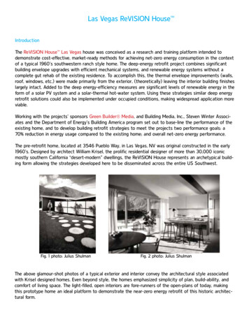
Chapter 3Chapter 3System ComponentsSystem ComponentsThe Series B Minneapolis Duct Blaster Systemconsists of the following components: Series B Duct Blaster FanTest Instrumentation (DG-700 Digital PressureGauge) and Fan Speed ControllerFlexible Extension DuctDuct Blaster Carrying Case3.1 Duct Blaster FanThe Series B Duct Blaster fan consists of a molded fan housing with a variable speed motor. The Duct Blasterfan will move up to 1,500 cubic feet of air per minute (CFM) at zero back pressure (i.e. free air), andapproximately 1,350 CFM against 50 Pascals (0.2 inches w.c.) of back pressure. With the flexible extensionduct attached, the fan will move 1,250 CFM (free air) and 1,000 CFM against 50 Pascals of back pressure. Fanflow is determined by measuring the slight vacuum created by the air flowing over the flow sensor attached tothe end of the motor. The Duct Blaster fan can accurately measure flows between 2.4 and 1,500 CFM using aseries of four calibrated Flow Rings which are attached to the fan inlet (see Appendix A for issues affecting fancalibration and accuracy). The Duct Blaster fan motor is not reversible, however the fan can be installed toeither pressurize or depressurize the duct system.Duct Blaster Fan with 3 Standard Flow RingsFlow Sensor on Duct Blaster FanThe Duct Blaster fan meets the flow calibration specifications of the following standards: CGSB 149.10-M86,ASTM E779, ASTM E1827, ASHRAE 152, EN 13829, ATTMA TS1, NFPA 2001, RESNET and USACE. TheMinneapolis Duct Blaster has a fan flow accuracy of /- 3 percent when using the DG-700 Digital PressureGauge. These calibration specifications include inaccuracies due to production tolerances of the fan andcalibration error of the gauge.6
Chapter 3System Components3.1.a Determining Fan Flow and Using the Flow Rings:Fan pressure readings from the flow sensor are easily converted to fan flow readings by reading flow directlyfrom the digital pressure gauge, using a Flow Conversion Table (see Appendix B), or through use of the TECsoftware programs and apps. The Duct Blaster fan has 5 different flow capacity ranges depending on theconfiguration of Flow Rings on the fan inlet. Table 1 below shows the approximate flow range of the DuctBlaster fan under each of the 5 Flow Ring configurations. The greatest accuracy in fan flow readings will alwaysbe achieved by installing the Flow Ring with the smallest opening area, while still providing the necessary fanflow to pressurize the duct system to the test pressure. Note: When taking Duct Blaster measurements, stand atleast 12 inches from the side of the fan inlet. Standing directly in front of the fan may affect the flow readingsand result in erroneous measurements. Also refer to Appendix A, Section A.2.c for information on the maximumallowable backpressures to ensure the flow calibration accuracy of the fan.Table 1: Fan Flow RangesFlow Ring ConfigurationOpen (no Flow Ring) *Ring 1Ring 2Ring 3Ring 4 (Optional)Flow Range (CFM)1,500 – 600800 – 225300 – 90125 – 1025 – 2.4Minimum Fan Pressure (Pa)25 Pa25 Pa25 Pa3 Pa5 Pa* The "Open" configuration can only be used when using the Duct Blaster fan to pressurize the duct system, notwhen depressurizing the duct system (see Chapters 9-11 for more information on depressurization testing).Flow Ring Installation:To install any of the Flow Rings, place the ring against the inlet of the fan sothat the outer edges of the ring roughly line up with the outer edge of the inletflange on the fan. Be sure the nozzle located in the middle of the ring ispointing inward toward the fan motor.Secure the outer edge of the Flow Ring and the fan flange together by pushingthe black connecting trim over both edges all the way around the fan flange.Note: You can also attach the Flow Rings using the four 2 inch longpieces of connecting trim found in the plastic parts bag stored in theaccessory case.7
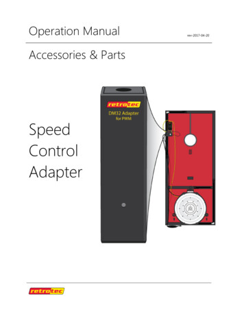
Chapter 3System ComponentsIn addition to the 3 Flow Rings, the Duct Blaster fan comes with a nylonfan cap to cover the inlet of fan, and a foam foot which can be used tostabilize the fan housing during fan operation.Note: Installation and use of optional Ring 4 is discussed in Appendix F.3.2 Test Instrumentation (DG-700 Pressure and Fan Flow Gauge)The DG-700 is a differential pressure gauge which measures the pressure difference between either of its Inputpressure taps and its corresponding bottom Reference pressure tap. The DG-700 gauge has two separatemeasurement channels which allows you to simultaneously monitor and display the duct system pressure and theflow through the Duct Blaster fan during the duct airtightness test. The digital gauge is shipped in a separatepadded case which is stored in the Duct Blaster accessory case. Also included is a black mounting board towhich the digital gauge can be attached using the Velcro strips found on the back of the gauge.DG-700 Pressure Gauge3.3 Fan Speed ControllerThe Duct Blaster fan is controlled by a variable fan speed controller. Fanspeed can be manually adjusted using the adjustment knob on the face ofthe speed controller. The speed controller is clipped onto the blackmounting board supplied with your Duct Blaster system. The Duct Blasterfan controller can be removed from the mounting board by sliding thecontroller clip off the board.Newer Duct Blaster fan speed controllers also contain a fan controlcommunication jack on the side of the device which can be used for cruisecontrol or computerized fan control.8
Chapter 3System Components3.4 Flexible Extension DuctThe flexible extension duct consists of a 12 foot long section of10" round flexible duct with one square and one round blackplastic transition piece attached at either end. The flexibleextension duc
Minneapolis Duct Blaster Operation Manual (Series B Systems) The Energy Conservatory 2801 21st Ave. S., Suite 160 Minneapolis, MN 55407 (612) 827-1117 (Ph) (612) 827-1051 (Fax) www.