Transcription
ASME Design Theory and Methodology Conference, 1996DESIGN FOR ASSEMBLY TECHNIQUES IN REVERSE ENGINEERING ANDREDESIGNDouglas D. LefeverPrince CorporationHolland, MIKristin L. Wood*Department of Mechanical EngineeringThe University of TexasETC 5.160Austin, TX 78712-1063ABSTRACTDesign for Assembly (DFA) is the process by which a product is designed to be easilyassembled. Such design simplifications are accomplished through reducing the number ofoperations required to assemble the product, improving the handling of each component, and/ormodifying the required operations (insertion, joining, etc.). There exist several techniques forassessing the assemblability of a design through an analysis of these three aspects. However,there also exists a clearly defined need for evolving such techniques to indicate how a productshould be redesigned with respect to customer needs and associated functionality. This paperpresents three such straightforward evolutions, aimed at reducing the number of components inan assembly during redesign. The first technique is a component elimination procedure, thesecond technique is a component combination analysis, and the third technique establishes alogical approach for revealing more abstract component elimination or combinationopportunities. These three DFA techniques are integrated within a reverse engineering andredesign methodology. They are then applied to a industrial design application, i.e., redesign ofan auxiliary automobile visor. Results demonstrate definitive part count reduction, whilemaintaining and improving design functionality.1 INTRODUCTION: REVERSE ENGINEERING, REDESIGN, AND DESIGN FORASSEMBLYReverse engineering is a redesign methodology. This means that it is a design process that isapplied to an existing product, or at least to a prototype or detailed concept. It is normally aprocess that uses a variety of techniques in the form of models, charts, diagrams, guidelines, andnormative theories to dissect and fully understand a product.Stated consisely, reverseengineering ".initiates the redesign process, wherein a product is observed, disassembled,analyzed, and documented in terms of its functionality, form, physical principles,1
ASME Design Theory and Methodology Conference, 1996manufacturability, and assemblability. The intent of this process step is to fully understand andrepresent the current instantiation of a product (Otto and Wood, 1996). "Although reverse engineering is most widely used for redesign purposes, it can be used forother reasons as well. There exists at least five possible motivations behind reverse engineeringa product: (1) benchmarking, (2) critical study and evaluation of a competitor's product, (3)quality improvements, (4) cost reduction, and (5) basic product/technology knowledge. Withinthis context, there can exist sub-design processes and methods that focus on a specific aspect ofthe design. Highly popular examples of these are Design for Manufacturing (DFM) and Designfor Assembly (DFA).Design for AssemblyDesign for Manufacturability and Design for Assembly can be considered sub-designprocesses.They are techniques that focus on specific issues (manufacturability andassemblability) within a design. In recent years, design for manufacturability (DFM) havedrawn a lot of attention. Companies have invested a great deal of effort and resources into newmanufacturing techniques like gas-assisted injection molding, powder metallurgy, and laserbeam machining (Kalpakijia, 1992). DFM software packages such as Computer-Aided ProcessPlanning (CAPP) (Kalpakijia, 1992) have provided engineers with tools during the design stages(Ullman, 1992; Dixon and Poli, 1995; Ulrich and Eppinger, 1994; Ettlie and Bridges, 1990).Assembly techniques have also received some focus. However, even though assemblytypically accounts for between 40 and 60% of the overall production time (Andreasen, 1983), ithas not received the same type of attention as manufacturing. Most of the progress in theassembly domain has come through studies of time and motion, division of work, and throughthe use of robotics and automation.Overall, only partial emphasis has been placed on assembly during the design phase. M.Andreasen, S. Kahler, and T. Lund blame this limited consideration for assembly during designon lack of time or deficient time planning, lack of realization as to the importance of assembly,lack of knowledge of design oriented assembly, the habit of saying "they usually work it out inproduction.", and/or organizational problems which restrict a fruitful co-operation betweenemployees from various functional areas (Andreasen, 1983).* Corresponding author.2
ASME Design Theory and Methodology Conference, 1996It is the presumption of this research that these problems are not the source, but rather theneed for further techniques in the area of DFA. This is not to say that DFA methods do not exist.Geoffrey Boothroyd and colleagues published their Product Design for Assembly manual in1982 (Boothroyd, Poli, and Murck, 1982; Boothroyd and Dewhurst, 1989, 1994; Ulrich andEppinger, 1994). This manual is regarded as the father or pioneer of DFA techniques. It iscomposed of a formalized step-by-step approach which they summarize as first, a selection ofthe assembly method - manual, high-speed automatic, or robot assembly, then an analysis of thedesign using a Design for Assembly Worksheet.The worksheet (or spreadsheet) takes intoaccount factors such as handling time, geometries, insertion time, and theoretical minimumnumber of parts to give an evaluation of the design which they label a product’s “designefficiency.” Besides Boothroyd and Dewhurst, many other DFA techniques have contributed tothe field and this research. They include (Poli, Graves, and Groppetti, 1986; Ishii, et al., 1995;Defazio and Whitney, 1987; Pine, et al., 1993; Lee and Yi, 1994; Kim and Bekey, 1993)Current DFA methods do a fine job of determining the assemblability of a product.However, it would be desirable to have a DFA method which would point directly at thesolutions needed to create a design that is more easily assembled. This situation is where thecurrent DFA techniques have some limitations. They expose the areas which negatively effecthow easily a product is assembled, but they do not provide an approach for solving these issues.It is extremely important to know why a particular design can be improved for ease of assembly,but linking this knowledge is a larger, more abstract problem.Niche: Piece Count Reduction in RedesignThis paper focuses on the aspect of DFA which considers piece count reduction. Piece countreduction means decreasing the number of parts that compose a product through either (1)elimination or (2) combination with other parts.Piece count reduction in many cases is the most effective means of improving assembly.Fewer parts means fewer operations, less handling, and quicker assembly (besides special casesidentified by Hinckley (1993)). Piece reduction also has broader implication. For example,Douglas Commercial Aircraft Co. ran simulations to determine what drives the cost of theirairline construction. They discovered that in addition to the costs of assembly, the costs offabrication, quality assurance, and even overhead-inventory levels, tracking, and purchasing alldepend on piece count (Ashley, 1995). Therefore, techniques that aid in redesigning a product3
ASME Design Theory and Methodology Conference, 1996for piece count reduction are needed. This paper presents techniques that help to accomplish thistask. The following is a list of the supporting objectives covered in the paper: (1) extend reverseengineering and DFA (piece count reduction) techniques; (2) develop a simple methodology tointegrate DFA (piece count reduction) techniques into an existing reverse engineeringmethodology; and (3) apply the methodology to industrial applications.A Reverse Engineering and Redesign MethodologyThe basis for our study for redesign is the reverse engineering and redesign methodology,shown graphically in Figure 1 (Otto and Wood, 1996; Ingle, 1994).This methodologyrepresents a ten-step process. It is a compilation of contemporary and extended engineeringdesign techniques, logically arranged in a systematic approachThe first six steps of the process aim at predicting and hypothesizing a product’s architecture,gathering and organizing customer needs, and subsequently developing a completeunderstanding of the product through disassembly, functional analysis, compatibility studies, andphysical modeling.The techniques used in these steps provide a means of not onlyunderstanding the physical product which is being analyzed, but also a mode for understandingthe design rationale that motivated the existing design. This rationale leads to a comprehensionof the "Whys" that motivated the "Hows" of a product. Steps 1-6 provide the supportingstructure for steps 7-10 which deal with the redesign of the product at a parametric, adaptive,and/or original level.2 TECHNIQUE EXTENSIONS: REDESIGN FOR PIECE COUNT REDUCTIONThe intent of this section is to present three techniques aimed at linking the evaluation of theassemblability of a product to the redesign of the product. There are many different types ofredesign that could lead to better assemblability. For instance, parametric redesign can be usedto adjust feature dimensions so parts can be handled or inserted more easily. The techniquespresented below, however, focus on redesign for piece count reduction at a higher level ofabstraction. This type of design is usually adaptive design and sometimes requires originaldesign. Parametric redesign is less likely to be used, as reduction of piece count usually requiresa combination of parts.However, if pieces can be simply eliminated from an assembly,parametric redesign may be required to compensate for variations caused through this4
ASME Design Theory and Methodology Conference, 1996elimination. An example of this is shown in the case study in a subsequent section. The threetechniques developed for aiding in redesign for piece count reduction are: Subtract and Operate ProcedureForce Flow DiagramsBoothroyd & Dewhurst ExtensionEach of these are explained through text and examples. For the Subtract and Operate Procedure,a simple mechanical example is used. For the Force Flow Diagrams and the Boothroyd &Dewhurst Extension, a current stapler product in the market is studied. Additional examplesmay be found in (Lefever, 1995). Also included is a discussion of how and where the techniquesare integrated into the reverse engineering and redesign methodology, captured in Figure 1.Subtract and Operate ProcedureOften, a product is over-designed. An over-designed product is one that uses multiplesolutions to solve subfunctions which could more efficiently be solved using fewer or a singlesolution.If this situation occurs, there is an opportunity for elimination of componentsproducing the redundancy. Identifying any redundant components can be a difficult undertaking.The Subtract and Operate Procedure (SOP) is a five step procedure aimed at exposing redundantcomponents in an assembly through the identification of the true functionality of eachcomponent:5
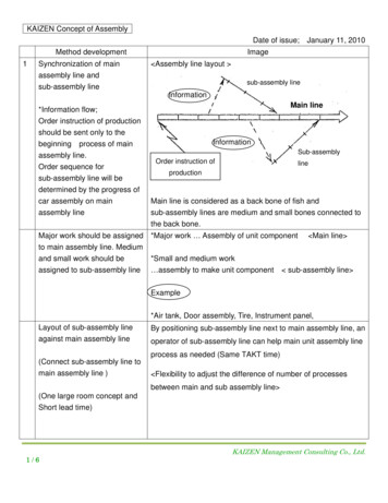
ASME Design Theory and Methodology Conference, 19961. Investigation, Prediction, and Hypothesis Develop black box modelUse/Experience productGather and organize customer needsPerform economic feasibility of redesignState process description or activity diagramHypothesize refined functional decompositionHypothesize product featuresList assumed working physical principles2-5. Concrete Experience: Function & Form Plan and execute product disassemblyCreate BOM, exploded view, and parameter listExecute and document Subtract/Operate ProcedureExperiment with product componentsDevelop Force Flow DiagramsCreate refined function structure of actual productCreate morphological matrixIdentify function sharing and compatibilityTransform to engineering specs. & metrics (QFD)6. Design Models Identify actual physical principles Create balance relationships Create engineering models and metric ranges— Example models: cost, heat transfer, stress,strength, life-cycle (DFE), assembly, etc. Alternatively or concurrently, build prototype model7. Design Analysis Calibrate Model Create engr. analysis, simulation, optimization,or spread sheet applications Create prototype model with design of experiments9. Adaptive Redesign8. ParametricRedesign Optimize designparameters Perform sensitivityanalysis/tolerance design Build and test prototype Recommend new subsystems Search new effects,principles, and TIPS trends Augment morph. matrix Analyze Force Flow forcomponent combinations Build and test prototype10. OriginalRedesign Develop new F.S.Choose alternativeBuild and test prototypeAlternatively, applyconcepts in new fieldFigure 1. A Reverse Engineering and Redesign Methodology.Step 1: Disassemble (subtract) one component of the assembly. Removal of componentsmay occur in any order. However, it may be necessary to remove one or several components inorder to remove the desired component. These prerequisite components should be reassembledif possible. If they cannot be reassembled, measures can be used to replicate the function(s) ofthe missing component(s). These measures are discussed later in this section.Step 2: Operate the system through its full range. This step should test the product throughthe range of customer and associated engineering requirements requirement (structural,ergonomic, kinematic, etc.). After removing a component, the product should be thoroughlytested to verify the effect of removal.Step 3:Analyze the effect.This step is most commonly completed through a visualanalysis. However, it may be necessary to use a testing device if the effect of removal is notobvious.6
ASME Design Theory and Methodology Conference, 1996Step 4: Deduce the subfunction(s) of the missing component. From step 3, the subfunctionof the missing component may be deduced. A change in any DOF during operation should be amajor focus. This issue is critical in determining component redundancies, as discussed in thissection.Step 5: Replace the component and repeat the procedure n times, where n is the number ofpieces in the assembly. Step 5 is the reassembly of the removed component. Repeating theprocess n times allows for the analysis of each component in the assembly. In certain cases, itmay be necessary to analyze a product according to subassemblies and components. This is alsotouched on later in this section.An example is given using a simple rotational constraint mechanism. This mechanism is asimple example used to clearly exhibit the SOP. The case study discussed later in this paper is amore complex, real world example. Following the example is a discussion of where the SOPshould be integrated into the redesign methodology.SOP ExampleFigure 2 shows an exploded view of a mechanism used to oscillate an arm through adesignated range. The arm is connected to a rotary shaft which oscillates. The shaft oscillates,but the range of rotation is constrained by the pins and the top plate slots.When applying the SOP five step procedure, it is useful to construct a matrix. Part number,part description, part function(s), and the observed effect(s) of operating the assembly withoutthe part are items that should be documented (in addition to the relationships with the customerneeds). For the mechanism shown in Figure 2, the worksheet is completed, as documented inTable 1. The SOP exposes five parts that are potential redundant components, denoted as "Noeffect" parts.Examining Figure 2, only one of the rotary pins is required to constrain the shaft's range ofrotation. For the arm pins, only one of the vertical pins (left or right) is required to constrain alldegrees of freedom of the arm. (This assumes that large loads are not applied to the arm and thatthe arm is square, rigid, and tightly toleranced with the shaft). Removing the horizontal pin hasno effect as the arm will not slip against the shaft because of the fixed vertical pins. A guidelinein using the SOP is, if a component has "No effect", leave it off and continue on to the nextcomponent. Hence, with the horizontal pin still removed, one of the vertical pins is removed.7
ASME Design Theory and Methodology Conference, 1996Top PlateWhen the system is operated, there is still "Noeffect" as the geometry of the arm and shaft alongFront RotaryPinwith the one fixed pin restrict any motion.For the purpose of this paper, classifyingRear Rotary PinRotary ShaftLeft VerticalArm PinRight VerticalArm Pincomponents as changing or not changing the DOFof a design when they are removed is the criticaldetermination.This leads to the followingproposition: Removed components causing noTable 1: SOP Example Device Worksheet.HorizontalEnd PinRotary ArmPartNo.Figure 2: SOP Example Device.Part descriptionEffect from Removal(Functions and Customer Needs)1Top Plate360 degree rotary freedom2Rotary ShaftNo torque transfer3Front Rotary PinNo effect4Rear Rotary PinNo effect5Rotary ArmNo torque transfer6Horizontal End PinNo effect7Right Vertical Arm PinNo effect8Left Vertical Arm PinNo effectchange in the DOF of the design are candidates for removal. Those components that cause nochange in the DOF as well as no other effects are termed Type 1 redundant components and canbe eliminated from the design. Those components that cause no change in the DOF, but haveother effects due to their removal, may be removed if another component can be parametricallyredesigned to compensate for these effects. These are Type 2 redundant components.Figure 2 is an example of Type 1 redundancies. An example of a Type 2 redundancy is adrawer with a handle. If the handle is removed, a ledge can be used to pull out the drawer, butthe effect is that there is an "Increase in pinch/grip effort." The drawer ledge geometry couldparametrically be redesigned to accommodate a hand and act as a handle. In a manner ofspeaking, the handle is a redundant component.8
ASME Design Theory and Methodology Conference, 1996The SOP can have limitations depending on the product being disassembled. Many times,the disassembly of a component requires the disassembly of other components. The simpleexample of a screw joining one block to a fixed block illustrates that to remove one block, thescrew will have to be removed as well. Components such as the screw in this case, can beconsidered functionally dependent components.This means that the screw's function isdependent on the removed block. Once the block is removed, the function of the screw becomesobsolete and the operation of the system will not be affected by its absence. In the case wherethe screw not only holds together one block, but also a second block to the fixed block, the screwwould be re-inserted before operation as it is functionally dependent on both blocks.There are situations in which operation of the product is difficult when a component isremoved. For these cases, it is useful to think of a product in a hierarchical manner: product,assemblies, subassemblies, etc. Decomposing the product into subassemblies and applying theSOP to each subassembly can eliminate the challenging or impossible task of operating the entiresystem. Components confined to the subassembly can be evaluated without regard to the rest ofthe assembly.Subassembly components interfacing with components outside of thesubassembly should be evaluated as they are integrated. In some cases, this evaluation may takesome creativity.External actuating or mounting tools can be used to resolve operatingchallenges.Integration: SOP and Reverse EngineeringFigure 1 shows how the SOP technique integrates into A Reverse Engineering DesignMethodology. Step 2 of the methodology is the disassembly of the product. At this stage, thepart number, part description, and function for each component is documented. The SOPworksheet could essentially be an extension of the Bill of Materials. The "Effect" column wouldneed to be added.In addition, the morphological analysis, in Step 4 of the methodology, can act as aredundancy check. Recall, in a morphological analysis (Otto and Wood, 1996; Pahl and Beitz,1989), the solution principle(s) (columns) are given for each subfunction (rows).Forsubfunctions solved by multiple solution principles, the different solution principles will appearin multiple columns. For a subfunction that is solved multiply by the same solution principle,the redundant solution principles will appear in as many columns as it is used in the design. Thisprocess is how redundancy discovered in the SOP will appear in the morphological matrix.9
ASME Design Theory and Methodology Conference, 1996For an over constrained design, in which "No effect" appears for a Type 1 component in theSOP worksheet, the subfunction embodied by the component will have redundant solutionprinciples. Furthermore, solution principles will not appear anywhere else in the morphologicalmatrix as function sharers, unless they are redundant for given subfunctions as well. If acomponent is deemed as a Type 2 redundant component, its solution principle will be a memberof a set of solution principles for a subfunction. Of the other solutions principles in the row, oneor more of their corresponding components can be parametrically altered to compensate for theelimination of the Type 2 redundant component. Therefore, the analysis of Type 2 redundanciesshould begin in step 6: Mathematically model product.The components involved in theparametric redesign should be modeled. In steps 7-8, the model should be solved, and theparametric redesign should be instituted.Force (Energy) Flow DiagramsWhile the SOP is a simple, common-sense method for exposing components for elimination,Force Flow Diagrams focus on the component combination. This concept is accomplishedthrough modeling of the design, then an analysis of the model.Force Flow Diagrams are diagrams which represent the transfer of force through a product'scomponents. The components are symbolized using circles (or squares), and the forces aredrawn as arrows connecting the components in which the force transfer takes place, whilemaintaining the general topological arrangement of the components. Consider the example ofthe three-piece paper clip shown in the Figure 3(a).In this case, the hand transfers the force to each of the lever arms. These arms in turntransfer the force to the clip, as represented with the Force Flow diagram in Figure 3(b).HandLeverArm 1PaperClipRHandClipLeverArm 2Hand(a)(b)Figure 3. Paper Clip Example.10R
ASME Design Theory and Methodology Conference, 1996The motivation behind constructing a Force Flow Diagram of a product is to map the forceflow through a product so that the diagram can be analyzed to help expose opportunities forcomponent/piece combination. The first step in analyzing a Force Flow Diagram is to place an"R" on the flows that have relative motion between two components.Once this step iscompleted, the diagram can be decomposed into groups separated by "R’s.” Having performedthis separation, the following proposition can be made: the components of the “R” groups can beeasily combined if not prohibited by material or assembly/disassembly issues. Combinationbetween a member of one group and a member outside of the group requires more complexredesign.To support this proposition, Force Flow Diagrams of a stapler are constructed and analyzed.A toy blender design is also analyzed in (Lefever, 1995). From these examples, hypotheticalpiece combinations are presented for some of the groups.Stapler ExampleAn exploded side view of the stapler under study is shown in Figure 4. It consists of twentyfour parts, and is indicative of many staplers currently on the market.The stapler has three sets of operations.Each set has a forward operation and acorresponding reverse operation. The three sets of operations for the stapler are: (1a) whenpushed on the top, the stapler extrudes a staple through the front side of a set of papers and bendsthe staple up into the back of the last page(s), (1b) when released, the stapler springs back into aready position; (2a) the impact plate can be pushed up and rotated 180o using the swivel button,(2b) and released back into the base so staples can be bent inward or outward into the page; (3a)to insert staples or remove failed staples, the top track can be disengaged with the bottom trackby lifting up on the top, and then (3b) re-engaged when completed.Force Flow diagrams of each of these operations can be individually constructed. For allthree, as should be expected when springs are loaded then unloaded, there will be a great deal ofredundancy in the diagrams. The flow direction simply reverses once the spring unloads.11
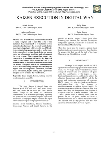
ASME Design Theory and Methodology Conference, 1996plastic coversteel topbracket springrivot 1top trackrivot 4connect bandrivot 5staple springslide footguide rodpivot rodbottom trackrivot 3pivot springimpact platerivot 2baseplate springswivel buttonrubber bottomFigure 4: Exploded Side View of Stapler.For this example, operation (1) is chosen. The hand provides the external force whichpushes down on the top. This force is transferred to the spring-bracket, to the top track, to thebottom track, through the pivot spring into the base, and out to an external surface. When thepivot spring is deflected enough, the upward reaction force overcomes the downward springbracket force. This force causes relative motion between the spring-bracket and the top andbottom tracks. This motion allows the spring-bracket to begin to push a staple out through thepages and onto the impact plate. In the meantime, the staple spring transfers force to the slidefoot and onto the staples. This keeps the front staple in place and moves the next staple up(horizontally) after the front staple has been displaced.Force flow occurs through all components except three (Figure 5). The connect band andrivets 4 and 5 are integral components for operation (3), but are not needed for operation (1).Placing "R’s” between relative moving components, and grouping them leads to Figure 5.Considering Group 1, it can be conceived that the plastic cover, the steel top, and the rivet couldall be combined as one component. This component would be a plastic top with a snap for thebracket-spring to connect.12
ASME Design Theory and Methodology Conference, 1996For Group 2, combination of the staple spring and slide foot could take place by using aspring that could push the staples itself. This modification would simply entail an additionalmanufacturing operation and parametric changes to the spring.platespringinitial springdeflection up 2staplespringinitial springdeflection pactplateRGroup rubberbottomexternalsurfaceGroup 5RpivotrodFigure 5. Stapler Force Flow Diagram.Moving to Group 3, the top track and bottom track could easily be combined. The top trackprovides the cover for the staples and a surface for the spring-bracket to force down. If thebottom track is enclosed, this combination would eliminate the need for the top track. However,an asterisk is placed between the top and bottom tracks in Figure 5 since these components haverelative motion on a Force Flow Diagram for one of the other operations. In this case, it isoperation (3): the input or removal of staples through the disengaging of the two tracks. Thismotion does not mean that it is impossible to combine the top and bottom track as there mightexist a design that would eliminate the need for disengaging the tracks.Examining Group 4, the entire group consisting of the plate spring, swivel button, rivet 3,and impact plate could be visualized as a single component, embodied in Figure 6. Again, theasterisk between the impact plate and base displays relative motion for a different operation.Disregarding operation (2) would lead to the conclusion that there is no relative motion betweenany of the parts and that they could all be integrated into the base.The final group is Group 5. It is feasible that rivet 2 and the base could be combined, and thepivot spring be press fitted onto a knob. The pivot spring and the base, however, require13
ASME Design Theory and Methodology Conference, 1996different materials as do the base and the rubber bottom. These components would be difficult tocombine.impact platebaseleaf springcombined pieceFigure 6. Impact plate redesign.The examples given for the combination of components in this design are redesigns thatcould be undertaken without affecting the functionality of other components. Attempting toconceptualize the combining of components outside of their groups means combining pieces thathave relative motion. Such combinations require a higher level of redesign that would likelyresult in the functional alteration of the other components. To visualize this situation, one canconceptualize the combination of the stapler’s components that are members of different groups.It is not trivial.Integration: Force Flow and Reverse Engr.Figure 1 shows where Force Flow Diagrams integrate into the methodology. Force FlowDiagrams should be constructed after disassembly. In many products, it would be difficult todetermine the force transfer between components before the product is disassembled. Step 3 ofA Reverse Engineering Methodology is to Learn and document the actual product function.This step is where the detailed function structure is generated, relating directly functionality offorce flows.The redesigns resulting from the Force Flow Diagram analysis are component combinationswhich are usually adaptive types of redesign. Hence, the analysis of the di
DESIGN FOR ASSEMBLY TECHNIQUES IN REVERSE ENGINEERING AND REDESIGN Douglas D. Lefever Prince Corporation Holland, MI Kristin L. Wood* Department of Mechanical Engineering The University of Texas ETC 5.160 Austin, TX 78712-1063 ABSTRACT Design for Assembly (DFA) is the process by which a