Transcription
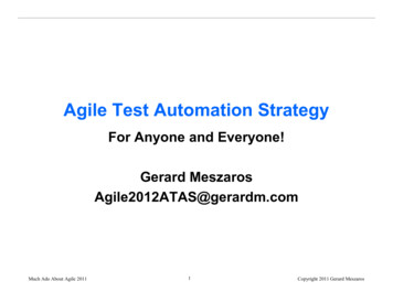
INTRODUCTION TO AUTOMATION SYSTEMUNIT 1 : INTRODUCTION TO AUTOMATION SYSTEMGeneral Objectives1. Understand and learn about automation control systems and types of automation controlsystems.2. Learn about the types of control system pneumatic control systems, hydraulic control systemsand electrical control system.Specific Objectives;At the end of this chapter, student should be able to:1.2.3.4.5.Define the Automation Control SystemStates the need of Automation Control System in the industryStates of the Fixed Automation / Hard-Wire Control SystemDifferentiate between Fixed Automation with Programmable Automation.State the basic concepts of pneumatic control systems, hydraulic control systems and electricalcontrol systems6. Classification of pneumatic control systems, hydraulic control systems and electrical controlsystems.7. Distinguish between the pneumatic control system, hydraulic control system and electricalcontrol systems1.0Introduction:In today’s fast-moving, highly competitive industrial world, a company must be flexible, costeffective and efficient if it wishes to survive. In the process and manufacturing industries, thishas resulted in a great demand for industrial control systems/ automation in order tostreamline operations in terms of speed, reliablity and product output. Automation plays anincreasingly important role in the world economy and in daily experience.Automation is the use of control systems and information technologies to reduce the need forhuman work in the production of goods and services. In the scope of industrialization,automation is a step beyond mechanization. Whereas mechanization provided humanoperators with machinery to assist them with the muscular requirements of work, automationgreatly decreases the need for human sensory and mental requirements as well.What is Automation Control System?Automation Control System - system that is able to control a process with minimal humanassistance or without manual and have the ability to initiate , adjust, action show or measuresthe variables in the process and stop the process in order to obtain the desired output.SARIATIPage 1
INTRODUCTION TO AUTOMATION SYSTEMThe main objective of Automation Control System used in the industry are:to increase productivityto improve quality of the productControl production cost1.2.3.1.1.1 Types Of Automation In The Industry1.1.1 Classification of automationa)Permanent/Fixed Automation-b)This control system is designed to perform a specific taskFunctions of control circuit is fixed and permanent.It will be complicated if we want to do other task apart from the existing taskProgrammable /Flexible Automation-1.1.2Programmable automation or felxible automation is a complex control system thatcan perform several tasksFunctions of control circuit programmed by the user and can be modified.When the task to be performed by machines changed, changes only need to be doneby making modifications to the machine control program.Comparison Between Fixed And Flexible Automation SystemPurposeEase of making changes / upgradeMaintenanceCapabilitySpeedEconomy SpecificVarietyDifficultEasyHardEasyDepends onmanufacturing anddesignVery highSlowFastSuitable for smallsystemSuitable forall types of systemsPage 2
Example :INTRODUCTION TO AUTOMATION SYSTEMFixed AutomationS1S2lampVsbBProgrammed 001OUT10000END (01)PLCINPUTOUTPUTLAMPS1S2COMCOMVsVsSARIATIPage 3
INTRODUCTION TO AUTOMATION SYSTEM1.1.3 There Are Three (3) Types Of The Control System Based On Supply :a) Pneumatic Control Systemsb) Hydraulic Control Systemc) Electrical Control Systema) Pneumatic Control System Pneumatic control system is a system that uses compressed air to produce power /energy to perform any task Pneumatic systems found in many industrial systems such as food industry,petrochemical and industrial involves robotics.Pneumatic systems requires:i. Compressed air supplyii. Control valveiii. Connecting tubeiv. Transducer Pneumatic control system can be controlled manually and automatically.Basic Block Diagram of Pneumatic Control System using manual/PLCSARIATIPage 4
INTRODUCTION TO AUTOMATION SYSTEMb) Hydraulic Control System Hydraulic control system is a system that uses fluid to generate power/energy. The hydraulic system used in the automobile industry such as power systems, braking systems,cranes, car jack, satellite and others. The fluid used is oil. The hydraulic system requires:a) Hydraulic fluid supplyb) Control Valvec) Cylinder Hydraulic control system can be controlled manually and automaticallyBasic block diagram of an automatic hydraulic control system by Manual /PLCc) Electrical Control System A control system that uses an electric current; either direct current (DC) or currentshuttle (AC) as a source of supply. Electrical Control Systems Generally requires:a) Electricity (DC) or (AC)b) Input elements (switches, sensors, transducer, valves, electronic components,etc.)c) Output elements (motor, lights, etc.)d) Extension cableSARIATIPage 5
INTRODUCTION TO AUTOMATION SYSTEMSwitchLampVsBasic block diagram of a manual electric control systemSwitchLampuPLCVsVsBasic block diagrams of electrical control system using PLCCOMPARISON BETWEEN PNEUMATIC CONTROL SYSTEMS ,HYDRAULICCONTROL SYSTEM AND ELECTRIC CONTROL SYSTEMSARIATIi.PNEUMATIC CONTROL SYSTEMa) Easy installationb) Simple designc) Use compressed air as a supply source to perform task.ii.HYDRAULIC CONTROL SYSTEMa) Complex to assembleb) Use fluid like oil as a supply source to perform task.c) Potential leakage will lead to pollution.iii.ELECTRIC CONTROL SYSTEMa) Simple systemb) Use electricity as a supply source to perform task.c) Widely use either for home user or in industrial.Page 6
INTRODUCTION TO AUTOMATION SYSTEM1.1.4 Advantages And Disadvantages Of Automation Control In IndustryThe main advantages of automation are: Replacing human operators in tasks that involve hard physical work.Replacing humans in tasks done in dangerous environments (i.e. fire, space, volcanoes,nuclear facilities, underwater, etc.)Performing tasks that are beyond human capabilities of size, weight, speed, endurance,etc.Economy improvement: Automation may improve in economy of enterprises, society ormost of humanity. For example, when an enterprise invests in automation, technologyrecovers its investment; or when a state or country increases its income due toautomation like Germany or Japan in the 20th Century.Reduces operation time and work handling time significantly.The main disadvantages of automation are: Unemployment rate increases due to machines replacing humans and putting thosehumans out of their jobs.Technical Limitation: Current technology is unable to automate all the desired tasks.Security Threats/Vulnerability: An automated system may have limited level ofintelligence, hence it is most likely susceptible to commit error.Unpredictable development costs: The research and development cost of automating aprocess may exceed the cost saved by the automation itself.High initial cost: The automation of a new product or plant requires a huge initialinvestment in comparison with the unit cost of the product, although the cost ofautomation is spread in many product batches of thingsTUTORIAL QUESTION: Give definition of Automation Control System? [3m] Make a comparison between Fixed Automation and Flexible Automation ControlSystem.[12m] State three (3) types of control system which based on supply source and states thedifferences between them.[12m] Sketch an automatic control system diagram for:a) Hydraulic Control Systemb) Electric Control Systemc) Pneumatic Control SystemSARIATIPage 7
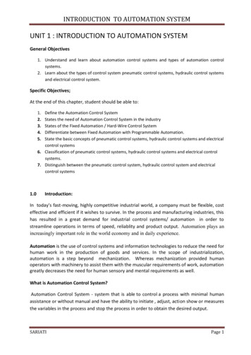
INTRODUCTION TO AUTOMATION SYSTEM1.2Explanation Of Relays And ContactorsThe representation of relays and contactors in the electrical circuit diagram is identical, astheir operating principle.i. Relays are used to switch relatively small output and current.ii. Contactor to switch relatively large output and currents.1.2.1 Relaysa) Definition RelayA relay is an electrically operated switch/electromagnetically actuated switch. Currentflowing through the coil of the relay creates a magnetic field which attracts a lever andchanges the switch contacts. The coil current can be ON or OFF so relays have two switchpositions and most have double throw (changeover) switch contacts .b) Types of RelaysRelays are usuallly SPDT (Single Pole Double Throw) or DPDT (Double Pole DoubleThrow) but they can have many more sets of switch contacts.Poles : the number of sets of contactsThrow : The number of positions or combinations (open or close) the contacts have.Several types of relays shown in the diagram below:Circuit symbol for a relaySARIATIPage 8
INTRODUCTION TO AUTOMATION SYSTEMThe relay's switch connections are usually labelled COM, NC and NO: COM Common, always connect to this, it is the moving part of the switch.NC Normally Closed, COM is connected to this when the relay coil is off.NO Normally Open, COM is connected to this when the relay coil is on.Connect to COM and NO if you want the switched circuit to be on when the relay coilis on.Connect to COM and NC if you want the switched circuit to be on when the relay coilis off.c) Relay Building DiagramRelaysThe actual relay building diagramA simple electromagnetic relay consists of a coil of wire wrapped around a soft ironcore , an iron yoke which provides a low reluctance path for magnetic flux, a movable ironarmature, and one or more sets of contacts. The armature is hinged to the yoke andmechanically linked to one or more sets of moving contacts. It is held in place by a spring sothat when the relay is de-energized there is an air gap in the magnetic circuit.When an electric current is passed through the coil it generates a magnetic field thatactivates the armature, and the consequent movement of the movable contact(s) eithermakes or breaks (depending upon construction) a connection with a fixed contact.If the set of contacts was closed when the relay was de-energized, then the movementopens the contacts and breaks the connection, and vice versa if the contacts were open.When the current to the coil is switched off, the armature is returned by a force,approximately half as strong as the magnetic force, to its relaxed position. Usually this force isprovided by a spring, but gravity is also used commonly in industrial motor starters. Mostrelays are manufactured to operate quickly. In a low-voltage application this reduces noise; ina high voltage or current application it reduces arcing.SARIATIPage 9
INTRODUCTION TO AUTOMATION SYSTEMRelay Building Diagram4132How Relays Work1. When switch is ON/press, the current will flow through it2. It will energize the electromagnet3. Then the coil (electromagnet) will attract the lever4. After the lever touch each other, the electricity will flow to the loadRelay can be used for various regulating, control and monitoring functions:i. As interfaces between control circuits and load circuitsii. For signal multiplicationiii. For separation of direct current and alternating current circuitsiv. For delaying, generating and converting signals andv. For linking information.SARIATIPage 10
INTRODUCTION TO AUTOMATION SYSTEMd) Example Of Relay Use In The Traffic Light System Operating Principle:This circuit can be used to control traffic in public places, or to demonstrate trafficrules in traffic-parks.IC2, which is heart of the circuit, is a decade counter. In this counter for every pulsefed to pin-14, potential keeps shifting from D1 to D9 in cyclic order.IC1 is used as a pulse generator and generates pulses in regular configurableintervals. These intervals can be changed by varying VR1.The circuit is designed in such a way that out of nine pulses, relay RL1 remainstriggered for 4 pulses, relay RL2 for 1 pulse and relay RL3 for remaining 4 pulses.Since D1-D4 provide current to T1, T1 is on whenever there is potential on any diodeD1 to D4, which keeps relay RL1 triggered. Similarly other diodes are responsible forRL2 and RL3 triggering.Red, Yellow and Green lamps can be connected to the relays RL1, RL2 and RL3respectively to complete your mini traffic light controller.SARIATIPage 11
INTRODUCTION TO AUTOMATION SYSTEM1.2.2 Contactorsd) Definition ContactorA relay that can handle the high power required (higher current rating) to directlycontrol an electric motor or other loads is called a contactor.A contactor is an electrically controlled switch used for switching a power circuit, similarto a relay except with higher current ratings.Contactors are used to control electric motors, lighting, heating, capacitor banks, andother electrical loads.b) Basic Component Of Contactor:A contactor has three components. The contacts are the current carrying part of thecontactor. This includes power contacts, auxiliary contacts, and contact springs. Theelectromagnet provides the driving force to close the contacts. The enclosure is a framehousing the contact and the electromagnet.ContactorContactor building diagramA basic contactor will have a coil input (which may be driven by either an AC or DCsupply depending on the contactor design). The coil may be energized at the same voltage asthe motor, or may be separately controlled with a lower coil voltage better suited to controlby programmable controllers and lower-voltage pilot devices.c)Operating PrincipleUnlike general-purpose relays, contactors are designed to be directly connected tohigh-current load devices. Relays tend to be of lower capacity and are usually designed forboth normally closed and normally open applications. Devices switching more than 15amperes or in circuits rated more than a few kilowatts are usually called contactors. Apartfrom optional auxiliary low current contacts, contactors are almost exclusively fitted withSARIATIPage 12
INTRODUCTION TO AUTOMATION SYSTEMnormally open contacts. Unlike relays, contactors are designed with features to control andsuppress the arc produced when interrupting heavy motor currents.When current passes through the electromagnet, a magnetic field is produced, whichattracts the moving core of the contactor. The electromagnet coil draws more current initially,until its inductance increases when the metal core enters the coil. The moving contact ispropelled by the moving core; the force developed by the electromagnet holds the movingand fixed contacts together. When the contactor coil is de-energized, gravity or a springreturns the electromagnet core to its initial position and opens the contacts.i.Main Contact.Main contact of the contactor are normaly open contact and usually use to connect powerload to the main supply.ii.Auxiliary ContactsAuxiliary contacts are secondary switching devices which work in conjunction with primaryswitching equipment such as circuit breakers, relays, and contactors. These contacts arephysically linked to the main switching mechanism and activate at the same time it does.Auxiliary contacts are commonly used as interlocks or retainers on the primary device'scontrol circuit and often used to give indication of its state of operation such as trip functionindication, electrical interlocks, and start circuit retainers. Many contactors and circuitbreakers feature sets of auxiliary contacts as integral parts or they may be modular snap onunits which can be added or removed as required. Auxiliary contacts are available with eithernormally open or normally closed contact points or a combination of both.d) Examples Application Of Contactor In Motor Control Sytem.1. DOL Motor Starter2. A STAR DELTA Motor StarterSARIATIPage 13
INTRODUCTION TO AUTOMATION SYSTEM1.2.3 Difference Between Relay And ContactorsThe Difference :1. Since a contactor is required for a higher load, a relay is always cheaper than acontactor.2. A relay is normally used in appliances below 5KW, while a contactor is preferredwhen the appliance is heavier.3. A relay is used only in control circuit while a contactor can be used in both controland power circuits.4. In general contactors are little slower than relays5. Contactor is so designed that it can be repaired while it is not normally done in thecase of relays.NOTES:It should be noted that when installing contactors or relays that you always check the coilratings. They often have not got a default rating of 230volts, and only go bang once if they areconnected to the wrong voltage!SARIATIPage 14
Differences between Pneumatic,Hydraulic and Electrical controlsystemPneumaticHydraulicElectric1Using Compress air assupply sourceUsing oil as supply sourceUsing electricity as asupply source2Easy installationComplicated InstallationSimple system3Simple designIf leak will cause dirtyWidespread use
Unit 1.2RELAY AND CONTACTOR
WHAT IS RELAY A relay is an electrically operated switch.Current flowing through the coil of the relaycreates a magnetic field which attracts a leverand changes the switch contacts. The coilcurrent can be on or off so relays have twoswitch positions and most have double throw(changeover) switch contacts as shown in thediagram.Symbol of relay
Several design of relay are in used today, 3pin,4-pin,5-pin,6-pin, single switch or dualswitches
Relay building diagram.1432
How relay works.1. When switch is ON/press, the current willflow through the coil.2. It will energize the electromagnet3. Then the coil (electromagnet) will attract thelever4. After the lever touch each other, theelectricity will flow to the load
Types of Relays Relays are usuallly SPDT (Single Pole DoubleThrow) or DPDT (Double Pole Double Throw)but they can have many more sets of switchcontacts. Poles : the number of sets of contacts Throw : The number of positions orcombinations (open or close) the contactshave.
Types of relay.This is a Single Pole DoubleSPDT-Single Pole Double Throw Throw relay. Current willflow between the movablecontact and one fixedcontact (NC) when the coilis de-energized.When the relay coil isenergized the current willflow between the movablecontact and the alternatefixed contact (NO).
DPDT – Double Pole Double ThrowThis relay is a DoublePole Double Throwrelay. It operates likethe SPDT relay buthas twice as manycontacts. There aretwo completelyisolated sets ofcontacts.
Types of Relays
Relay application Relay can be used for various regulating,control and monitoring functions: As interfaces between control circuits and load circuits For signal multiplication For separation of direct current and alternating currentcircuits For delaying, generating and converting signals and For linking information.
Example of Relay Application:1. Vehicle horn
2. Relay in Traffic Light System
Operating Principle: This circuit can be used to control traffic in public places, or todemonstrate traffic rules in traffic-parks. IC2, which is heart of the circuit, is a decade counter. In this counterfor every pulse fed to pin-14, potential keeps shifting from D1 to D9 incyclic order. IC1 is used as a pulse generator and generates pulses in regularconfigurable intervals. These intervals can be changed by varying VR1. The circuit is designed in such a way that out of nine pulses, relay RL1remains triggered for 4 pulses, relay RL2 for 1 pulse and relay RL3 forremaining 4 pulses. Since D1-D4 provide current to T1, T1 is onwhenever there is potential on any diode D1 to D4, which keeps relayRL1 triggered. Similarly other diodes are responsible for RL2 and RL3triggering. Red, Yellow and Green lamps can be connected to the relays RL1, RL2and RL3 respectively to complete your mini traffic light controller.
WHAT IS CONTACTORA contactor is an electricallycontrolled switch used forswitching a power circuit,similar to a relay except withhigher current ratings.A contactor is controlled by acircuit which has a much lowerpower level than the switchedcircuit.
How the contactor works When current passes through the electromagnet, a magneticfield is produced, which attracts the moving core of thecontactor. The electromagnet coil draws more current initially, until itsinductance increases when the metal core enters the coil. Themoving contact is propelled by the moving core; the forcedeveloped by the electromagnet holds the moving and fixedcontacts together. When the contactor coil is de-energized, gravity or a springreturns the electromagnet core to its initial position andopens the contacts.
Examples Application OfContactor1. STAR-DELTA Motor Starter
Examples Application OfContactor2. DOL Motor Starter
Relay vs ContactorRELAYCONTACTORUse for lower load, below 5KWLight duty switchUse for high loadHeavy duty switchcontrolled device that opens andcloses electrical contacts to effect theoperation of other devices in thesame or another circuit.for repeatedly establishing andinterrupting an electrical powercircuitrelay is used in control circuit onlycontactor is used in both controland power circuit.CheaperExpensiveNot economically to repairDesigned that it can be repaired
INTRODUCTION TO PLCCHAPTER 2: INTRODUCTION TO PLCObjectives:At the end of this lecture the students should be able to:1. Describe a PLC and its functions2. Explain the history of PLC development3. Identify the mains part of PLC and describe the functions.4. List the types and advantages of PLC2.0INTRODUCTIONIn this chapter , we will discussed about PLC in detail:2.1 Definition of PLC2.2 Define PLC Terminologies2.3 Background PLC2.3 The function of PLC and Types of Construction2.4 Advantages of PLCs2.1Definition of PLCDefinition according to NEMA standard ICS3-1978A digitally operating electronic apparatus which uses a programming memory for theinternal storage of instructions for implementing specific functions such as logic,sequencing, timing, counting and arithmetic to control through digital or analog modules,various types of machines or process.ORA device that is pre-programmed to accept relay ladder logic instructions and perform theseinstructions to control the equipment operation.SARIATIPage 1
2.2PLC Terminologiessensors:INTRODUCTION TO PLCswitches, flow, level, pressure, temp. transmitters, etc.output devices/actuators:SARIATImotors, valves, solenoids, lamps, or audible devicesPage 2
INTRODUCTION TO PLCCPU - Central Processing Unit.The CPU is a microprocessor that co-ordinates the activities of the PLC system. Its executesthe program, processes I/O signals & communicates with external devicesLadder Diagram Ladder diagrams are specialized schematics commonly used to document industrial controllogic systems. They are called "ladder" diagrams because they resemble a ladder, with twovertical rails (supply power) and as many "rungs" (horizontal lines) as there are controlcircuits to represent built from relays, is being simulated2.2Background of PLCAmong the factors that create the initial design and development of control systemsthat can be controlled are as follows:i. Requirements of a low costii. Intelligent systemiii. The Controller that is easy to controlThe first PLC was designed by a team of engineers at the company GeneralMotors (GM), the United States in 1968 when the company is looking for other methodsto replace the complex system of relays. They also set the specifications of the newcontrol system must meet the following requirements:i. Easily programmedii. There is no need for rewiring if there are changes on the programiii. Smaller, cheaper and higher reliability.iv. Simple building construction and the maintenance cost is cheap.v. Cost competitiveSARIATIPage 3
INTRODUCTION TO PLC2.3 FUNCTIONS AND TYPE OF CONSTRUCTION2.3.1Function of PLCPLC can perform various functions, such as follows :Type of controlFunctionSequence Control1. Successor Control Relay - conventional logic2. Timer/counter3. Substitute PCB Control card4. Machine and Process Controller for Automatic, Semiauto and manual1.Advanced Control2.3.4.5.6.Solve Mathematics of Operations( , , , x)Managing InformationAnalog control (temperature, pressure, etc.)Servo Motor ControlStepper motor controlcontrol P.I.D (Propotional - Integral - derivation)1. Process Display and Alarm2. Diagnosis and Display Fault3. Interface with Computer(RS 232C / RS 422)4. Interface Printer / ASCII5. Factory Automation Network6. Local Area Network (LAN)7. Widespread Area Network (WAN)8. Factory Automation (FA),Flexible ManufacturingSystem (FMS), Computer Integrated Manufacturing(CIM) etc.Supervision control2.3.2 Type of PLC ConstructionFigure 2.3.2 shows the types of PLC construction in the market today.Types of PLC construction.SARIATIPage 4
INTRODUCTION TO PLC2.4. Advantages of PLC are as follows: SARIATIThe implementation of a short control projects.Program can be change easily.Accurate calculation of the cost project.Requires a short training time.Flexible control system design using the software.A wide range of control applications.Easy maintenance.High reliabilityA standard Hardware controllerResistance to the problems of the environment (temperature,moisture, voltage instability and noise) is good.Page 5
PLC HARDWARE DESIGNCHAPTER 3 – PLC HARDWARE DESIGNObjectives:After completed this chapter, the student will know the major components of a PLC and thefunctions of these components.Introduction:The PLC, being a microprocessor based device, has a similar internal structure to manyembedded controllers and computers. A PLC consist of the following components:i.ii.iii.iv.v.CPU,MemoryInput modulesOutput modulesPower supply.These components are integral to the PLC controller. Additionally the PLC has a connectionfor the Programming and Monitoring Unit, Printer and Program Recorder.3.1Hardware Design of PLCDATA ataInputUnit/Module( CPU )OutputUnit/ModuleOutputUnitADDRESS BUSCONTROLLED BUSa) Design Of A Basic MicrocomputerSARIATIPage 1
PLC HARDWARE DESIGNb) PLC Hardware Block Diagram3.1.1 Explanation of the PLC Block DiagramThe programming terminal in the diagram (b) is not part of the PLC, but it is essential tohave a terminal for programming or monitoring a PLC. In the diagram , the arrows betweenblocks indicate the information and power flowing directions.a) Central Processing Unit - CPUThis unit is the most important unit in the building of a PLC , which is the “brain” of a PLC.In this unit lies a chip of microprocessor - intergrated circuit chips which controls the overalloperation of the PLC control system. Microprocessors contain arithmatic unit, control unitand a number of memory units, known as registrars.The main function of the microprocessor is to analyze data coming from field sensorsthrough input modules, make decisions based on the user’s defined control program andreturn signal back through output modules to the field output devices.In detail, the CPU of a PLC does the following operation: Updating inputs and outputs. This function allows a OLC to read the status of itsinput terminals and energize or deenergize its output terminals. Performing logic and arithmetic operations. A CPU conducts all the mathematic andlogic operations involved in a PLC. Communicating with memory. The PLC programs and data are stored in memory.When a PLC operating, its CPU may read or change the contents of memorylocations. Scanning application programs. An application program , which is called a ladderlogic program , is a set of instructions written by a PLC programmer. The scanningfunction allows the PLC to execute the application program as specified by theprogrammer.SARIATIPage 2
PLC HARDWARE DESIGNCommunicating with a programming terminal. The CPU transfers program and databetween itself and the programming terminal.b) Memory UnitMemory is the component that stores information, programs and data in a PLC. Theprocess of putting new information into a memory location is called writing. Theprocess of retrieving information from a memory location is called reading.Above figure shows the memory unit in the internal design of PLCs. This unit containstwo (2) types of memory:i.RAM (Random Access Memory)RAM is the memory type of read / write and easy to program and repaired.All users program are stored in this memory. Read indicates that the informationstored in the memory can be retrieved or read, while write indicates that theuser can program or write information into the memory. The data in the RAMwould normally be lost if the power source is removed. This problem is solved bybacking up the RAM with the batteryii.ROM (Read Only Memory)ROM is read-only memory types. Read Only indicates that the information storedin memory can be read only and cannot be changed. Information in ROM isplaced there by the manufacturer for the internal use and operation of the PLC.The system program is stored in this memory. This program will not be lost whenthe power is disconnected. Special equipment is used to delete the programfrom this memoryThe memory capacities of PLCs vary.c)Display and Indicators UnitDisplay and the indicator unit refers to the internal relay PLC status display. This can be seenin the Console programming if the user using the mnemonic code and programmingcomputer screen if the user using software programming methods.d)Input And Output Unit /ModuleSARIATIPage 3
PLC HARDWARE DESIGNReferring to above figure, the input and output units are the units available in the internaldesign of PLCs.The Input/Output units are the interfaces between the internal PLC systems and theexternal processes/ field devices to be monitored and controlled. Input Unit is the unitwhich input devices (switches, sensors) are connected to it. While the output unit is a unitwhich output devices (Lights, motors) are connected to it.The main purpose of the I/O interface is to condition the various signals received from orsen
Automation is the use of control systems and information technologies to reduce the need for human work in the production of goods and services. In the scope of industrialization, automation is a step beyond mechanization. Whereas mechanization provided