Transcription
SECTION 10TransformerInstallations
10-1TRANSFORMERS – GENERALOur general policy on transformer sizes and types are listed on page 10 – 3 and our generalpolicy on U/G vs. O/H and services voltage is discussed on page 1-1. We have now standardizedon a low loss transformer design as dictated by our high cost of generation (re losses) and inkeeping with international environmental and energy conservation standards.The low loss transformers are heavier because of the increase in the amount of core steel andwinding material required to reduce losses; however, to compensate for this we have reduced therecommended size for three phase banks and will encourage U/G wherever possible.CALCULATING TRANSFORMER LOADSThe KVA and/or Amperes load is calculated, for any voltage, using the following formulae:(a)(b)SINGLE PHASEKVA Amperes x Voltage1000Amperes KVA x 1000VoltageTHREE PHASEKVA 3 x Amperes x Voltage1000Amperes KVA x 1000 3 x VoltageTransformer – Full Load AmperesSingle hree 80V90135180271361601902120318042406
10-2THREE PHASE: OPEN WYE – OPEN DELTANO NEW INSTALATIONS MAINTENANCE ONLYMany of our services consist of a large single-phase load (120/240V) and a small three-phaseload (240V); these are normally serviced with a two transformer, three-phase bank (closed delta,open delta). Both transformers carry the three-phase load and one carries the single-phase load.When using a open wye, open delta, each transformer is required to carry 58% of the three phaseload. The transformers are normally referred to as the power transformer (carries three phaseload only- smaller transformer and the lighting transformer (carries single phase load in additionto the three phase load – larger transformer).For example, if a service is required to carry a single phase load of 28 KVA and a phase load of11 KVA, the required transformer sizes are:-Single PhaseThree Phase (0.58 x 11)Total LoadActual TFMR SIZELarge TFMR28 KVA6.4 KVA34.4 KVA37.5 KVASmall TFMR6.4 KVA6.4 KVA10.0 KVAAnother example – assuming a three-phase load requirement (customer) of 203 amperes, 37amperes and 203 amperes, the transformer sizes can be determined as follows:(a)The three phase load is 37 amperes;KVA 3 x amperes x voltage 3 x 37 x 240 15.410001000When using two transformers the requirement is 0.58 x 15.4 KVA 8.9 KVA foreach of the two transformers. Therefore a 10 KVA is adequate for the powertransformer.(b)The single-phase load is 203 amperes, less the three-phase load of 37 amperes (203 –37 166 amperes).KVA amperes x voltage 166 x 240 39.810001000(c)The lighting transformer size is now:- Single phase – 39.8 KVA, plus three phase –8.9 KVA 48.7 KVA.The power transformer (three phase) size is 10 KVA (load 8.9 KVA) and thelighting or load transformer size if 50 KVA (8.9 KVA 39.8 KVA 48.7 KVA).
10-3Since our smallest size transformer is 15 KVA (there may be some older 10KVA’s available) wewill have to use a 15KVA for the power transformer; a 50 KVA transformer is satisfactory forthe lighting load, however, if additional capacity is required for growth, a 75 KVA will have tobe used – now our bank size is a 15 KVA and a 74 KVA.When calculating the load (KVA) for an existing three-phase (two transformer) bank, use thelighting transformer leg with the higher ampere reading.
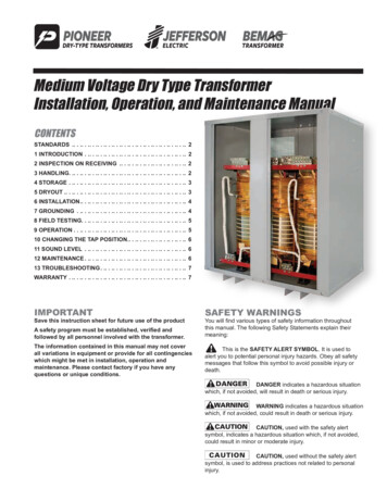
10-4LOCATING TRANSFORMERS ON THE POLEThe location of the transformer(s) on certain structures has an effect on the integrity of structure.Large single-phase transformers should never be placed on the side of a structure but rather onthe front of the structure; the location of small transformers is not so important.The overturning moment resulting from installing the transformer on the side of a pole issubstantial; the resulting moment from a 167KVA transformer Is equivalent to the pressure of a45MPH wind on a single phase structure with 2/0 conductor. Unlike wind the overturningmoment due to the transformer is continuous and in most cases will cause the pole to lean –which in turn will increase the overturning moment.In some cases where the transformer tank is long or the space on the pole is not as per standards,we may want to lower the transformer location; the overturning moment can be minimized byinstalling the transformer off line, enough to clear the neutral or the neutral and secondaryconductors. The clearance from the transformer tank to the neutral can be minimal as both are atground potential; however the clearance from the transformer tank to the secondary conductorsmust be a minimum of 6 inches. With guyed structures (type B) it is normally quite practical tolower the transformer location and maintain the required clearance to the secondary conductors.The bottom of the transformer shall not be less than 24’0” from the ground on any structure withcommunication attachments.It is a good practice to use only type “A”, “B” and “DE” structure types for transformerinstallations. The installation of transformers on structures type “DV” structures require workingaround working clearances, guys, cutouts, etc and not recommended.It is also a good practice to minimize the number of HV connections at a structure; limit thestructure to either a HV tap or transformer(s), preferably not both. Although we cannot determinethe location of a primary tap, we normally have alternatives for the transformer location,particularly single phase installations.
10-5TRANSFORMER TYPESOur specifications call for an internal arrester in all pole-mounted transformers. We do howeverhave number of older transformers with no internal arrester; these transformers will require anexternal lightning arrester. All pad-mounted transformers will be protected by a lightning arresterat the cable dip.The standardized size and type of single-phase transformers are:Single Phase TransformersSIZE (KVA) TYPE AND VOLTAGEPole Mounted 75100100100100*167167*250250*Existing but not recommended for future Three Phase banks.Three Phase Dead Front – Pad Mounted TransformersSIZE (KVA) TYPE AND VOLTAGE240/120 Volt ForMaintenance onlyLoop225300500120/208 Volt277/480 ORMER INSTALLATIONSOur overhead three phase transformer bank installations will generally be limited to 300KVA (3100 KVA’s); Open delta banks should be limited to 167 KVA for the lighting transformer.Pad mounted transformers will generally be used for all three phase loads of 300 KVA andlarger; 120/208 & 240/120 volt services are limited to 500 KVA. Our preferred voltage for threephase services, 300 KVA and larger 277/480 volt.
10-6Transformer Lead SizeTransformerRating (KVA)10 To 50PrimaryLead#2 SDBC75 & 100#2 SDBCSecondary LeadNeutralHot1-4/0 AAC1-4/0 AACInsulatedInsulated1-4/0 AAC2-4/0 AACInsulatedInsulatedTransformerGround#2 SDBC#2 SDBCFuse Link and Current Limiting FuseTransformer RatingKVA10152537.55075100167250333Fuse Size (7200/1,500 Volts)Fuse LinkCLF1.4 SF12 K2.1 SF12 K3.5 SF12 K5.2 SF12 K7.0 SF12 K10.4 SF25 K14.0 SF25 K21.0 SF40 K32.0 SF40 K46.0 SF40 KTransformer Weight & Height – Pole MountedRating KVA10152537.55075100167250Weight Range (lbs)Standard Loss Low Loss NewOlder TypesStd.Height Range (lbs)Older TypesLow Loss NewStd.
10- 7GUIDELINES FOR FUSING PROTECTION OFDISTRIBUTION TRANSFORMERSSINGLE-PHASE TRANSFORMERS(Polemounted or padmounted, in 1-phase or 3-phase applications)Tx. Size(kVA)152537.55075100167250333Fuse size(Amps)2.13.55.27.010.414.021.032.050.0Fuse astSloFastTA.B. ChanceCatalogue 23M14SFA23M21SFA23M32SFA23M50TA23CUC StockNumberLIN 374 000 11LIN 374 000 12LIN 374 000 15LIN 374 000 19LIN 374 000 20LIN 374 000 17LIN 374 000 18LIN 374 000 13LIN 372 000 02THREE-PHASE TRANSFORMERSTx. Size(kVA)150225300500750100015002000Fuse size(Amps)7.010.414.021.032.050.080.0100.0Fuse TypeSloFastSloFastSloFastSloFastSloFastTTTA.B. ChanceCatalogue 50TA23M80TA23M100TA23CUC StockNumberLIN 374 000 19LIN 374 000 20LIN 374 000 17LIN 374 000 18LIN 374 000 13LIN 372 000 02LIN 372 000 03LIN 372 000 04
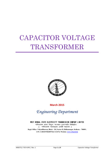
THREE PHASE TRANSFORMER - FULL LOAD AMPERES208KVAH.V.120 VV240 510.42108362554130013.89144383372250023.152406 1388120375034.723608 20821804100046.304811 27762406150069.457217 41643608200092.609623 IRUSH25ICLP-6ICLP-3ICLP-2IHLP-12IHLP-15IN 57.5833.41736.21111.22315.0277 V15620831346962510421563208431264169480 846.369.492.6138.9185.2HOT LOAD 1041.71111.21389.0COLD LOAD 8.9208.3277.8IN RUSH @ 12 TIMES RATED CURRENT @ 0.01 SECONDSIN RUSH @ 25 TIMES RATED CURRENT @ 0.01 SECONDSCOLD LOAD PICK UP @ 6 TIMES RATED CURRENT @ 1 SECONDCOLD LOAD PICK UP @ 3 TIMES RATED CURRENT @ 10 SECONDSCOLD LOAD PICK UP @ 2 TIMES RATED CURRENT @ 900 SECONDHOT LOAD PICKUP @ 12 TIMES RATED CURRENT @ 0.1 SECONDHOT LOAD PICKUP @ 15 TIMES RATED CURRENT @ 0.1 SECOND120208240277480THREE PHASE H.V.12020824027748012470
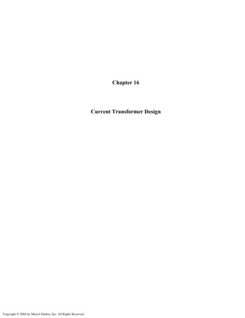
SINGLE PHASE TRANSFORMER - FULL LOAD AMPERES240KVAH.V.120 2104156208313417696IN CLP-68.312.520.831.341.762.583.3139.2COLD LOAD 0SINGLE PHASEH.V.ICLP-22.84.26.910.413.920.827.846.4HOT LOAD .183.3104.2125.0156.3166.7208.3278.3347.9IN RUSH @ 12 TIMES RATED CURRENT @ 0.01 SECONDSIN RUSH @ 25 TIMES RATED CURRENT @ 0.01 SECONDSCOLD LOAD PICK UP @ 6 TIMES RATED CURRENT @ 1 SECONDCOLD LOAD PICK UP @ 3 TIMES RATED CURRENT @ 10 SECONDSCOLD LOAD PICK UP @ 2 TIMES RATED CURRENT @ 900 SECONDHOT LOAD PICKUP @ 12 TIMES RATED CURRENT @ 0.1 SECONDHOT LOAD PICKUP @ 15 TIMES RATED CURRENT @ 0.1 SECOND1202404807200
transformer. (b) The single-phase load is 203 amperes, less the three-phase load of 37 amperes (203 – 37 166 amperes). KVA amperes x voltage 166 x 240 39.8 1000 1000 (c) The lighting transformer size is now:- Single phase – 39.8 KVA, plus three phase – 8.9 KVA 48.7 KVA. The power transformer