Transcription
IV. Three-Phase TransfomersThree-Phase TransfomersThe majority of the power generation/distribution systems in the world are 3phase systems. The transformers for such circuits can be constructed either as a3-phase bank of independent identical transformers (can be replacedindependently) or as a single transformer wound on a single 3-legged core(lighter, smaller, cheaper and slightly more efficient).1
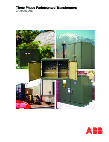
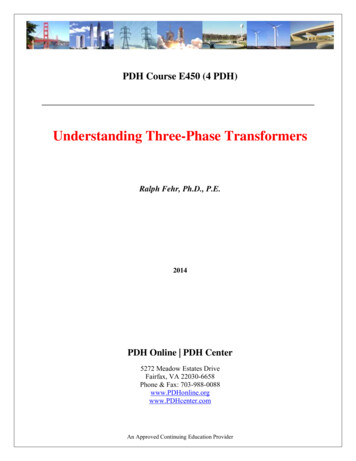
We assume that any single transformer in a 3-phase transformer (bank) behavesexactly as a single-phase transformer. The impedance, voltage regulation,efficiency, and other calculations for 3-phase transformers are done on a perphase basis, using the techniques studied previously for single-phasetransformers.Four possible connections for a 3-phase transformer bank are:1) Y-Y2) Y-Δ3) Δ-Δ4) Δ-YCommon three-phase transformer connections. The transformerwindings are indicated by the heavy lines.2
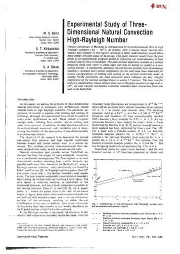
1) Y-Y connectionThe primary voltage on each phaseof the transformer is:V P VLP3The secondary phase voltage is:VLS 3V SThe overall voltage ratio is:3V PVLP aVLS3V SThe Y-Y connection is seldom used as it has two very serious problems:a) If loads on one of the transformer circuits are unbalanced, the voltages onthe phases of the transformer can become severely unbalanced.b) The third harmonic issue. The voltages in any phase of an Y-Y transformer are120 apart from the voltages in any other phase. However, the third-harmoniccomponents of each phase will be in phase with each other. Nonlinearities inthe transformer core always lead to generation of third harmonic! Thesecomponents will add up resulting in large (can be even larger than thefundamental component) third harmonic component.Both problems can be solved by one of two techniques:i) Solidly ground the neutral of the transformers (especially, the primaryside). The third harmonic will flow in the neutral and a return path will beestablished for the unbalanced loads.ii) Add a third Δ-connected winding. A circulating current at the thirdharmonic will flow through it suppressing the third harmonic in other windings.3
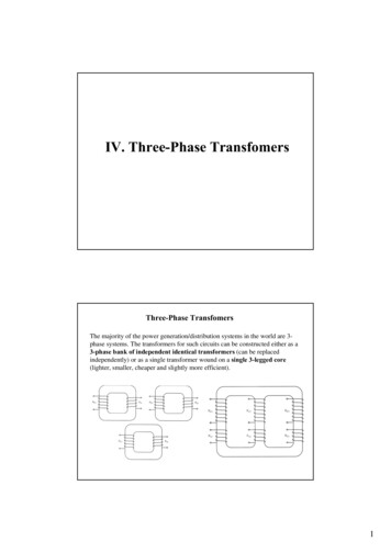
2) Y-Δ connectionThe primary voltage on each phaseof the transformer is:V P VLP3The secondary phase voltage is:VLS V SThe overall voltage ratio is:3V PVLP 3aVLSV SThe Y-Δ connection has no problem with third harmonic components, sincethey are consumed in a circulating current on the Δ side. It is also morestable to unbalanced loads since the Δ partially redistributes any imbalancethat occurs.One problem associated with this connection is that the secondary voltageis shifted by 30 with respect to the primary voltage. This can causeproblems when paralleling 3-phase transformers since transformerssecondary voltages must be in-phase to be paralleled. Therefore, we mustpay attention to these shifts.In the U.S., it is common (actually it is a standard now) to make thesecondary voltage to lag the primary voltage. The connection shown in theprevious slide will do it.The Y-Δ connection is generally used in stepping down from a highvoltage to a medium or low voltage. One reason is that a neutral is therebyprovided for grounding on the high-voltage side, a procedure which can beshown to be desirable in many cases.4
3) Δ-Y connectionThe primary voltage on each phaseof the transformer is:V P VLPThe secondary phase voltage is:VLS 3V SThe overall voltage ratio is:VVLPa P VLS3V S3The Δ-Y connection has the same advantages and the same phase shift as theY-Δ connection.The Δ-Y connection is commonly used for stepping up to a high voltage.5
4) Δ-Δ connectionThe primary voltage on each phaseof the transformer is:V P VLPThe secondary phase voltage is:VLS V SThe overall voltage ratio is:VLP V P aVLS V SThe Δ-Δ connection has no phase shift and no problems with unbalancedloads or harmonics.The Δ-Δ connection has the advantage that one transformer can beremoved for repair or maintenance while the remaining tow continue tofunction as a three-phase bank with the rating reduced to 58% of that of theoriginal bank; this is known as the open-delta, or V, connection.6
Analyzing Three-Phase Transformer Circuits1.2.3.4.5.6.7.For fixed line-to-line voltages and total fixed kVA rating of the 3-phasetransformer, the kVA rating of each transformer is 1/3rd of total kVA ratingof bank regardless of the connection type.Voltage and current values of individual transformers depend on connectiontype (Y or Δ)Circuit computations involving 3-phase transformer banks can be made bydealing with only one phase and recognizing that condition are same forother 3 phases except a 120 phase displacementComputations are carried out on a per-phase Y line-to-neutral basis, sincethe transformer impedances in a Y-connected can be added directly in serieswith transmission line impedanceThe impedances of transmission lines can be referred from one side to otherby the use of square of ideal line-to-line voltage ratio of the bank.In dealing with Y-Δ or Δ-Y banks, all quantities should be referred to Yconnected side for simplicityIn dealing with Δ-Δ banks in series with transmission lines, it is convenientto replace Δ-connected transformer impedance into Y-connected ones.Per-Unit System for Three-Phase TransfomersThe per-unit system applies to the 3-phase transformers as well as to singlephase transformers.If the total base VA value of the transformer bank is Sbase, the base VA value ofone of the transformers will beSS1 ,base base3Therefore, the base phase current and impedance of the transformer areI ,base Z baseS1 ,baseV ,base V ,base S1 ,base 2 Sbase3 V ,base3 V ,base 2Sbase7
The line quantities on 3-phase transformer banks can also be represented in perunit system.If the windings are in Δ: VL ,base V ,baseIf the windings are in Y: VL ,base 3V ,baseAnd the base line current in a 3-phase transformer bank is:I L ,base Sbase3VL ,baseThe application of the per-unit system to 3-phase transformer problems is similarto its application in single-phase situations.The voltage regulation of the transformer bank is the same.Ex 1. A 50 kVA, 13800/208V Δ-Y transformer has a resistance of 1% and areactance of 7% per unit.a) What is the transformer’s phase impedance referred to the high voltage side?b) What is the transformer’s voltage regulation at full load and 0.8 pf lagging,using the calculated high-side impedance?c) What is the transformer’s voltage regulation under the same conditions, usingthe per-unit system?a) The high-voltage side of the transformer has the base voltage 13 800 V and abase apparent power of 50 kVA. Since the primary side is Δ-connected, itsphase voltage and the line voltage are the same.The base impedance is:Z base 3 V ,base Sbase23 13 800 11 426 50 0002 8
The per-unit impedance of the transformer is:Z eq , pu 0.01 j 0.07 puTherefore, the high-side impedance in ohms is:Z eq Z eq , pu Z base 0.01 j 0.07 11 426 114 j800 b) The voltage regulation of a 3-phase transformer equals to a voltage regulationof a single transformer:VR V P aV SaV S 100%The rated phase current on the primary side can be found as:I 50 000S 1.208 A3V 3 13 800The rated phase voltage on the secondary of the transformer isV S 208 120 V3When referred to the primary (high-voltage) side, this voltage becomesV S ' aV S 13 800 VAssuming that the transformer secondary winding is working at the rated voltageand current, the resulting primary phase voltage isV P aV S ReqI jXeqI 13800 0 114.2 1.208 cos 1( 0.8) j 800 1.208 cos 1( 0.8) 14490 j690.3 14506 2.73 VThe voltage regulation, therefore, isVR V P aV SaV S 100% 14 506 13 800 100% 5.1%13 8009
c) In the per-unit system, the output voltage is 1 0 , and the current is1 cos-1(-0.8). Therefore, the input voltage isV P 1 0 0.01 1 cos 1 (0.8) j 0.07 1 cos 1 (0.8) 1.051 2.73 Thus, the voltage regulation in per-unit system will beVR 1.051 1.0 100% 5.1%1.0The voltage regulation in per-unit system is the same as computed in volts Ex 2. Three 2400:240V single-phase transformers connected in Δ-Δ and suppliedwith power through a 3-phase feeder (i.e. cable) connected at high-voltage sidewhose reactance is j0.8 /phase. The equivalent reactance of each transformerreferred to high-voltage side is j1.82 /phase. Other circuit resistances arenegligible. At its sending end (i.e. primary-side), the feeder is connected to thesecondary terminals of a Y-Δ connected 3-phase transformer whose rating is500kVA 24000:2400V. The equivalent reactance of sending end transformer isj2.76 /phase referred to 2400V side. The voltage applied to primary of thesending end transformer is 24kV. A 3-phase short-circuit occurs at 240V terminalsof the receiving end transformer (i.e. load side). Compute the steady-state shortcircuit current in the feeder wires, primary of receiving end and actual value of theshort circuit current.10
And the base line current in a 3-phase transformer bank is:, 3 , base Lbase Lbase S I V The application of the per-unit system to 3-phase transformer problems is similar to its application in single-phase situations. The voltage regulation of the transformer