Transcription
SpringerHandbookof Experimental SolidMechanicsSharpe (Ed.)With DVD-ROM, 874 Figures, 58 in four color and 50 Tables123
Editor:Professor William N. Sharpe, Jr.Department of Mechanical EngineeringRoom 126, Latrobe HallThe Johns Hopkins University3400 North Charles StreetBaltimore, MD 21218-2681, USAsharpe@jhu.eduLibrary of Congress Control Number:ISBN: 978-0-387-26883-52008920731e-ISBN: 978-0-387-30877-7c 2008,Springer Science Business Media, LLC New YorkAll rights reserved. This work may not be translated or copied in wholeor in part without the written permission of the publisher (Springer Science Business Media, LLC New York, 233 Spring Street, New York, NY10013, USA), except for brief excerpts in connection with reviews or scholarly analysis. Use in connection with any form of information storage andretrieval, electronic adaptation, computer software, or by similar or dissimilar methodology now known or hereafter developed is forbidden. The usein this publication of trade names, trademarks, service marks, and similarterms, even if they are not identified as such, is not to be taken as an expression of opinion as to whether or not they are subject to proprietary rights.The use of designations, trademarks, etc. in this publication does not imply,even in the absence of a specific statement, that such names are exempt fromthe relevant protective laws and regulations and therefore free for generaluse.Product liability: The publisher cannot guarantee the accuracy of anyinformation about dosage and application contained in this book. In everyindividual case the user must check such information by consulting therelevant literature.Production and typesetting: le-tex publishing services oHG, LeipzigSenior Manager Springer Handbook: Dr. W. Skolaut, HeidelbergTypography and layout: schreiberVIS, SeeheimIllustrations: Hippmann GbR, SchwarzenbruckCover design: eStudio Calamar Steinen, BarcelonaCover production: WMXDesign GmbH, HeidelbergPrinting and binding: Stürtz GmbH, WürzburgPrinted on acid free paperSPIN 115100799085/3820/YL543210
187Electrochemo8. Electrochemomechanicsof Ionic Polymer–Metal CompositesSia Nemat-NasserThe ionomeric polymer–metal composites (IPMCs)consist of polyelectrolyte membranes, with metalelectrodes plated on both faces and neutralized with an amount of counterions, balancing thecharge of anions covalently fixed to the membrane.IPMCs in the solvated state form soft actuators andsensors; they are sometimes referred to as artificialmuscles. Here, we examine the nanoscale chemoelectromechanical mechanisms that underpin themacroscale actuation and sensing of IPMCs, as wellas some of their electromechanical properties.8.2.2 Pressure in Clusters . 1928.2.3 Membrane Stiffness . 1928.2.4 IPMC Stiffness . 1928.3 Voltage-Induced Cation Distribution . 1938.3.1 Equilibrium Cation Distribution . 1948.4 Nanomechanics of Actuation .8.4.1 Cluster Pressure ChangeDue to Cation Migration .8.4.2 Cluster Solvent UptakeDue to Cation Migration .8.4.3 Voltage-Induced Actuation.1951951961978.5 Experimental Verification . 1978.5.1 Evaluationof Basic Physical Properties . 1978.5.2 Experimental Verification . 1988.2 Stiffness Versus Solvation . 1918.2.1 The Stress Fieldin the Backbone Polymer . 1918.6 Potential Applications . 199References . 199Polyelectrolytes are polymers that carry covalentlybound positive or negative charges. They occur naturally, such as deoxyribonucleic acid (DNA) andribonucleic acid (RNA), or they have been manuRfactured for various applications, such as Nafion R or Flemion , which consist of three-dimensionallystructured backbone perfluorinated copolymers of polytetrafluoroethylene, having regularly spaced long perfluorovinyl ether pendant side-chains that terminatein ionic sulfonate (Nafion) or carboxylate (Flemion)groups. The resulting Nafion or Flemion membranes arepermeable to water or other polar solvents and cations,while they are impermeable to anions.The ionomeric polymer–metal composites (IPMCs)consist of polyelectrolyte membranes, about 200 μmthick, with metal electrodes (5–10 μm thick) plated onboth faces [8.1] (Fig. 8.1). The polyelectrolyte matrixis neutralized with an amount of counterions, balancingthe charge of anions covalently fixed to the membrane.When an IPMC in the solvated (e.g., hydrated) state isstimulated with a suddenly applied small (1–3 V, depending on the solvent) step potential, both the fixedanions and mobile counterions are subjected to an electric field, with the counterions being able to diffusetoward one of the electrodes. As a result, the compositeundergoes an initial fast bending deformation, followedby a slow relaxation, either in the same or in the opposite direction, depending on the composition of thebackbone ionomer, and the nature of the counterion andthe solvent. The magnitude and speed of the initial fastdeflection also depend on the same factors, as well ason the structure of the electrodes, and other conditions(e.g., the time variation of the imposed voltage). IPMCsthat are made from Nafion and are neutralized with alkali metals or with alkyl-ammonium cations (except fortetrabutylammonium, TBA ), invariably first bend to-Microstructure and Actuation.8.1.1 Composition .8.1.2 Cluster Size .8.1.3 Actuation .Part A 81881881891918.1
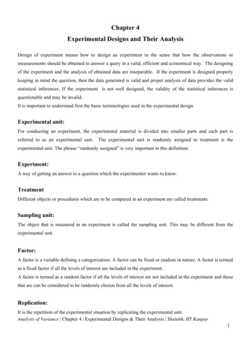
188Part ASolid Mechanics Topicsa)b)Au platingFig. 8.1a,b Cross section of (a) aPt/Au-plated Nafion-117 membraneat electrode region; the length ofthe bar is 408 nm; and (b) an Auplated Flemion at electrode region;the length of the bar is 1 μmAu platingPlatinumparticlesAu408 nmFlemionwards the anode under a step direct current (DC), andthen relax towards the cathode while the applied voltage is being maintained, often moving beyond theirstarting position. In this case, the motion towards theanode can be eliminated by slowly increasing the applied potential at a suitable rate. For Flemion-basedIPMCs, on the other hand, the initial fast bending andthe subsequent relaxation are both towards the anode,for all counterions that have been considered. WithTBA as the counterion, no noticeable relaxation towards the cathode has been recorded for either Nafionor Flemion-based IPMCs. Under an alternating electric1μmpotential, cantilevered strips of IPMCs perform bendingoscillations at the frequency of the applied voltage, usually no more than a few to a few tens of hertz, dependingon the solvent. When an IPMC membrane is suddenlybent, a small voltage of the order of millivolts is produced across its faces. Hence, IPMCs of this kind canserve as soft actuators and sensors. They are sometimesreferred to as artificial muscles [8.2, 3].In this chapter, we examine the nanoscale chemoelectromechanical factors that underpin the macroscaleactuation and sensing of IPMCs, as well as some of theirelectromechanical properties.8.1 Microstructure and Actuation8.1.1 CompositionThe Nafion-based IPMC, in the dry state, is about180 μm thick and the Flemion-based one is about160 μm thick (see [8.4–7] for further information onIPMC manufacturing). Samples consist of1. backbone perfluorinated copolymer of polytetrafluoroethylene with perfluorinated vinyl ether sulfonate pendants for Nafion-based and perfluorinatedb) Nanosizeda)interconnected clustersCracked metal overlayerMetalcoatingPart A 8.1Ionic polymer Naflonor Flamion0.2 mmCluster groupFig. 8.2 (a) A schematic representation of an IPMC and (b) a transmission electron microscopy (TEM) photo of the cluster structure(see Fig. 8.3 for more detail)propyl ether carboxylate pendants for Flemionbased IPMCs, forming interconnected nanoscaleclusters ([8.8]; primary physical data for fluorinatedionomers have been summarized in [8.9])2. electrodes, which in Nafion-based IPMCs consistof 3–10 nm-diameter platinum particles, distributedmainly within a 10–20 μm depth of both faces of themembrane, and usually covered with about 1 μmthick gold plating to improve surface conductivity,while in Flemion-based IPMCs, the electrodes aregold, with a dendritic structure, as shown in Fig. 8.13. neutralizing cations4. a solventFigure 8.2 shows a schematic representation of a typicalIPMC, including a photograph of the nanostructure ofthe ionomer (Nafion, in this case), and a sketch of ionicpolymer with metal coating. Figure 8.3 shows some additional details of a Nafion-based IPMC. The dark spotswithin the inset are the left-over platinum crystals.The ion exchange capacity (IEC) of an ionomerrepresents the amount of sulfonate (in Nafion) andcarboxylate (in Flemion) group in the material, mea-
Electrochemomechanics of Ionic Polymer–Metal Compositesa)Metal overlayer1μm8.1 Microstructure and Actuationb)189c)OOOOOOPlatinum diffusion zone (0 –25 μm)Fig. 8.4 (a) Chemical structure of 18-Crown-6 (each node is CH2 );(b) Na ion; and (c) K ion within a macrocyclic 18-Crown-6ligand8.1.2 Cluster SizeLeft-over platinumparticles20 nmFig. 8.3 Near-surface structure of an IPMC; the lower in-set indicates the size of a typical cluster in Nafion 2 3NkT 3 NEWionUela aI,ρ NA h 2 ρB wρsρ ,1 w(8.1)where N is the number of dipoles inside a typical cluster, k is Boltzmann’s constant, T is the temperature, h 2 is the mean end-to-end chain length, ρ is the effective density of the solvated membrane, and NA isAvogadro’s number (6.023 1023 ). The electrostatic en-Part A 8.1sured in moles per unit dry polymer mass. The drybare ionomer equivalent weight (EW) is defined as theweight in grams of dry ionomer per mole of its anion.The ion exchange capacity and the equivalent weightof Nafion are 0.91 meq/g and 1.100 g/mol, and thoseof Flemion are 1.44 meq/g and 694.4 g/mol, respectively.For neutralizing counterions, we have used Li ,Na , K , Rb , Cs , Mg2 , and Al3 , as well as alkylammonium cations TMA , TEA , TPA , and TBA .The properties of the bare ionomer, as well as thoseof the corresponding IPMC, change with the cationtype for the same membrane and solvent. In additionto water, ethylene glycol, glycerol, and crown ethershave been used as solvents. Ethylene glycol or 1,2ethanediol (C2 H6 O2 ) is an organic polar solvent thatcan be used over a wide range of temperatures. Glycerol, or 1,2,3-propanetriol (C3 H8 O3 ) is another polarsolvent with high viscosity (about 1000 times the viscosity of water). Crown ethers are cyclic oligomersof ethylene glycol that serve as macrocyclic ligandsto surround and transport cations (Fig. 8.4). The required crown ether depends on the size of the ion.The 12-Crown-4 (12CR4) matches Li , 15-Crown-5(15CR5) matches K , and 18-Crown-6 matched Na and K . For example, an 18-Crown-6 (18CR6) molecule has a cavity of 2.7 Å and is suitable for potassiumions of 2.66 Å diameter. A schematic configuration ofthis crown with sodium and potassium ions is shownin Fig. 8.4.X-ray scanning of the Nafion membranes [8.10] hasshown that, in the process of solvent absorption, hydrophilic regions consisting of clusters are formedwithin the membrane. Hydrophilicity and hydrophobicity are generally terms used for affinity or lack ofaffinity toward the polar molecule of water. In thepresent work we use these terms for interaction towardany polar solvent (e.g., ethylene–glycol). Cluster formation is promoted by the aggregation of hydrophilicionic sulfonate groups located at the terminuses of vinylether sulfonate pendants of the polytetrafluoroethylenechain. While these regions are hydrophilic, the membrane backbone is hydrophobic and it is believed thatthe motion of the solvent takes place among these clusters via the connecting channels. The characteristicsof these clusters and channels are important factors inIPMC behavior. The size of the solvated cluster radiusaI depends on the cation form, the type of solvent used,and the amount of solvation. The average cluster sizecan be calculated by minimizing the free energy of thecluster formation with respect to the cluster size. Thetotal energy for cluster formation consists of an elasticUela , an electrostatic Uele , and a surface Usur component. The elastic energy is given by [8.11]
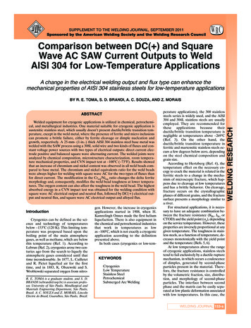
190Part ASolid Mechanics Topicsa13 (nm3)151050Modelx-ray00.511.522.53η 105Fig. 8.5 Cluster size in Nafion membranes with differentsolvent uptakesergy is given byUele gN 2 m2,4πκe aI3where n is the number of clusters present in the membrane. Minimizing this energy with respect to clustertot 0, gives the optimum cluster size atsize, U aIwhich the free energy of the ionomer is minimum. Inthis manner Li and Nemat-Nasser [8.11] have obtained γ h 2 EWion (w ΔV )aI 2RTρB 2 1/34πρB 1 3 ,3ρ (w ΔV )NA Vi ρd,(8.5)EWionwhere Vi is the volume of a single ion exchange site.Assuming that h 2 EWion β [8.12], it can be seen that,ΔV (8.2)aI3 2EW2ion (w ΔV )4πρB3η 1 .ρB3ρ (w ΔV )where g is a geometric factor, m is the dipole moment,and κe is the effective permittivity within the cluster.The surface energy can be expressed as(8.6)Usur 4πaI2 γ ,(8.3)where γ is the surface energy density of the cluster.Therefore, the total energy due to the presence of clusters in the ionomer is given byUtot n(Uele Uela Usur ) ,a)γβη,2RT(8.4)(c) t 4m 45sFigure 8.5 shows the variation of the cluster size(aI3 in nm3 ) for different solvent uptakes. Data fromNafion-based IPMC samples with different cations anddifferent solvent uptakes are considered. The model iscompared with the experimental results on the cluster size based on x-ray scanning, shown as circlesb)c)–(d) t 6 m 27s–R t 3mst 210mst 5mst 129ms 1cm(a) t 0(b) t 0.6 st 10mst 54mst 36mst 15mst 24msFig. 8.6 (a) A Nafion-based sample in the thallium (I) ion form is hydrated and a 1 V DC signal is suddenly appliedPart A 8.1and maintained during the first 5 min, after which the voltage is removed and the two electrodes are shorted. Initial fastbend toward the bottom ((a) to (b), anode) occurs during the first 0.6 s, followed by a long relaxation upward (towardsthe cathode (c)) over 4.75 min. Upon shorting, the sample displays a fast bend in the same upward direction (not shown),followed by a slow downward relaxation (to (d)) during the next 1.75 min. (b) A Nafion-based sample in the sodiumion form is solvated with glycerol, and a 2 V DC signal is suddenly applied and maintained. It deforms into a perfectcircle, but its qualitative response is the same. (c) A Flemion-based sample in tetrabutylammonium ion form is hydrated,and a 3 V DC signal is suddenly applied and maintained, resulting in continuous bending towards the anode (no backrelaxation)
Electrochemomechanics of Ionic Polymer–Metal Compositesin Fig. 8.5 for a Nafion ionomer in various cation formsand with water as the solvent [8.10]. We have setβ 1.547, γ 0.15, and Vi 68 10 24 cm3 to calculate the cluster size [8.12].8.1.3 ActuationA Nafion-based IPMC sample in the solvated stateperforms an oscillatory bending motion when an alternating voltage is imposed across its faces, and itproduces a voltage when suddenly bent. When thesame strip is subjected to a suddenly imposed andsustained constant voltage (DC) across its faces, aninitial fast displacement (towards the anode) is gen-8.2 Stiffness Versus Solvation191erally followed by a slow relaxation in the reversedirection (towards the cathode). If the two faces ofthe strip are then shorted during this slow relaxation towards the cathode, a sudden fast motion inthe same direction (towards the cathode) occurs, followed by a slow relaxation in the opposite direction(towards the anode). Figure 8.6 illustrates these processes for a hydrated Tl -form Nafion-based IPMC(left), Na -form with glycerol as solvent (middle), andhydrated Flemion-based in TBA -form (right), under1, 2, and 3 V DC, respectively. The magnitudes of thefast motion and the relaxation that follows the fastmotion change with the corresponding cation and thesolvent.8.2 Stiffness Versus SolvationTo model the actuation of the IPMC samples interms of the chemoelectromechanical characteristics ofthe backbone ionomer, the electrodes, the neutralizing cation, the solvent, and the level of solvation, itis first necessary to model the stiffness of the corresponding samples. This is discussed in the presentsection.A dry sample of a bare polymer or an IPMC placedin a solvent bath absorbs solvent until the resulting pressure within its clusters is balanced by the elastic stressesthat are consequently developed within its backbonepolymer membrane. From this observation the stiffnessof the membrane can be estimated as a function of thesolvent uptake for various cations. Consider first thebalance of the cluster pressure and the elastic stressesfor the bare polymer (no metal plating) and then usethe results to calculate the stiffness of the corresponding IPMC by including the effect of the added metalelectrodes. The procedure also provides a way of estimating many of the nanostructural parameters thatare needed for the modeling of the actuation of theIPMCs.8.2.1 The Stress Fieldin the Backbone Polymerσr (r0 ) p0 K [(r0 /a0 ) 3 (w/w0 1) 1] 4/3 ,σθ (r0 ) σϕ (r0 ) p0 K [(r0 /a0 ) 3 (w/w0 1) 1]2/3 ,(8.7)where r0 measures the initial radial length from thecenter of the cluster, and w0 is the initial (dry) volume fraction of the voids. Theeffective elastic resistanceof the (homogenized solvated) membrane balancesthe cluster’s pressure pc which is produced by thecombined osmotic and electrostatic forces within thecluster.Part A 8.2The stresses within the backbone polymer may beestimated by modeling the polymer matrix as an incompressible elastic material [8.13, 14]. Here, it will proveadequate to consider a neo-Hookean model for the matrix material. In this model, the principal stresses σI arerelated to the principal stretches λI by σI p0 K λ2I ,where p0 is an undetermined parameter (pressure) tobe calculated from the boundary data and K is an effective stiffness, approximately equal to a third of theoverall Young’s modulus. The aim is to calculate K andp0 as functions of the solvent uptake w for various ionform membranes. To this end, examine the deformationof a unit cell of the solvated polyelectrolyte (bare membrane) by considering a spherical cavity of initial (i. e.,dry state) radius a0 (representing a typical cluster), embedded at the center of a spherical matrix of initialradius R0 , and placed in a homogenized solvated membrane, referred to as the matrix. In micromechanics, thisis called the double-inclusion model [8.15]. Assume thatthe stiffness of both the spherical shell and the homogenized matrix is the same as that of the (as yet unknown)overall effective stiffness of the hydrated membrane.For an isotropic expansion of a typical cluster, the twohoop stretches (and stresses) are equal, and using theincompressibility condition and spherical coordinates,it follows that
192Part ASolid Mechanics Topics8.2.2 Pressure in ClustersFor the solvated bare membrane or an IPMC in theM -ion form, and in the absence of an applied electric field, the pressure within each cluster pc consistsof osmotic Π(M ) and electrostatic pDD components.The electrostatic component is produced by the ionicinteraction within the cluster. The cation–anion conjugate pairs can be represented as uniformly distributeddipoles on the surface of a spherical cluster, and theresulting dipole–dipole (DD) interaction forces pDDcalculated. The osmotic pressure is calculated by examining the difference between the chemical potentialof the free (bath) solvent and that of the solvent withina typical cluster of known ion concentration within themembrane. In this manner, one obtains [8.16]νQ 1 2 α2B K0φQ, pc w3κe B w2RTρB FK0 ,, Q B FEWionby the volume of solid), respectively. The membraneYoung’s modulus may now be set equal to YB 3K (w),assuming that both the elastomer and solvent are essentially incompressible under the involved conditions.8.2.4 IPMC StiffnessTo include the effect of the metal plating on the stiffness, note that for the Nafion-based IPMCs the goldplating is about a 1 μm layer on both faces of an IPMCstrip, while platinum particles are distributed throughthe first 10–20 μm surface regions, with diminishingdensity. Assume a uniaxial stress state and average theaxial strain and stress over the strip’s volume to obtaintheir average values, asε̄IPMC f MH ε̄B (1 f MH )ε̄M ,σ̄IPMC f MH σ̄B (1 f MH )σ̄M ,f MH fM,1 w(8.10)(8.8)where φ is the practical osmotic coefficient, α is the effective length of the dipole, F is the Faraday constant,ν is the cation–anion valence (ν 2 for monovalentcations), R 8.314 J/mol/K is the universal gas constant, T is the cluster temperature, ρB is the density ofthe bare ionomer, and κe is the effective permittivity.where the barred quantities are the average values ofthe axial strain and stress in the IPMC, bare (solvated) membrane, and metal electrodes, respectively(indicated by the corresponding subscripts ‘B’ and‘M’, respectively); and f M is the volume fraction ofthe metal plating in a dry sample. Setting σ̄B YB ε̄B ,σ̄M YM ε̄M , and σ̄IPMC ȲIPMC ε̄IPMC , it follows thatYM YB,BAB YM (1 BAB )YB(1 w̄)(1 f M )B , w w̄(1 f M ) ,1 w̄(1 f M )ȲIPMC 8.2.3 Membrane StiffnessThe radial stress σr must equal the pressure pc in thecluster at r0 a0 . In addition, the volume average ofthe stress tensor, taken over the entire membrane, mustvanish in the absence of any externally applied loads.This is a consistency condition that to a degree accountsfor the interaction among clusters. These conditions aresufficient to yield the undetermined pressure p0 andthe stiffness K in terms of solvation volume fractionw and the initial dry void volume fraction w0 for eachion-form bare membrane, leading to the following finalclosed-form results:1 w,w0 In (w0 /w)4/31 2An 01 2Aw , A 1 ,In 1/31/3w0n 0 (1 An 0 )(1 A)K pcPart A 8.2(8.9)where n 0 and w0 n 0 /(1 n 0 ) are the initial (dry)porosity and initial void ratio (volume of voids divided(8.11)where AB is the concentration factor, giving the average stress in the bare polymer in terms of the averagestress of the IPMC σ̄IPMC . Here YB 3K is evaluatedfrom (8.9) at solvation w̄ when the solvation of theIPMC is w. The latter can be measured directly at various solvation levels.Experimentally, the dry and solvated dimensions(thickness, width, and length) and masses of each bareor plated sample are measured. Knowing the composition of the ionomer, the neutralizing cation, and thecomposition of the electrodes, all physical quantitiesin equations (8.8) and (8.11) are then known for eachsample, except for the three parameters α, κe , and AB ,namely the effective distance between the neutralizing cation and its conjugate covalently fixed anion, theeffective electric permittivity of the cluster, and the concentration factor that defines the fraction of axial stress
Electrochemomechanics of Ionic Polymer–Metal Compositescarried by the bare elastomer in the IPMC. The parameters α and κe are functions of the solvation level.They play critical roles in controlling the electrostaticand chemical interaction forces within the clusters, aswill be shown later in this chapter in connection withthe IPMC’s actuation. Thus, they must be evaluatedwith care and with due regard for the physics of theprocess.Estimate of κe and αThe solvents are polar molecules, carrying an electrostatic dipole. Water, for example, has a dipole momentof about 1.87 D (Debyes) in the gaseous state and about2.42 D in bulk at room temperature, the difference beingdue to the electrostatic pull of other water molecules.Because of this, water forms a primary and a secondaryhydration shell around a charged ion. Its dielectric constant as a hydration shell of an ion (about 6) is thus muchsmaller than that in bulk (about 78). The second term inexpression (8.8) for the cluster pressure pc , can changeby a factor of 13 for water as the solvent, dependingon whether the water molecules are free or constrainedto a hydration shell. Similar comments apply to othersolvents. For example, for glycerol and ethylene glycol, the room-temperature dielectric constants are about9 and 8 as solvation shells, and 46 and 41 when inbulk.When the cluster contains both free and ion-boundsolvent molecules, its effective electric permittivitycan be estimated using a micromechanical model. Letκ1 ε1 κ0 and κ2 ε2 κ0 be the electric permittivity ofthe solvent in a solvation shell and in bulk, respectively,where κ0 8.85 10 12 F/m is the electric permittivity of free space. Then, using a double-inclusion8.3 Voltage-Induced Cation Distribution193model [8.15] it can be shown thatκ2 2κ1 f (κ2 κ1 )κ1 ,κe κ2 2κ1 f (κ2 κ1 )m w CNEWion wf , mw (8.12).mwMsolvent ρB νHere, CN is the static solvation shell (equal to the coordination number), m w is the number of moles of solventper mole of ion (cation and anion), and ν 2. When m wis less than CN, then all solvent molecules are part of thesolvation shell, for which κe ε1 κ0 . On the other hand,when there are more solvent molecules, equation (8.12)yields the corresponding value of κe . Thus, κe is calculated in a cluster in terms of the cluster’s volumefraction of solvent, w.Similarly, the dipole arm α in (8.8), which measuresthe average distance between a conjugate pair of anion–cation, is expected to depend on the effective dielectricconstant of the solvation medium. We now calculate theparameter α2 , as follows. As a first approximation, welet α2 vary linearly with w for m w CN, i. e., we set α 2 a1 w a2 ,form w CN ,(8.13)and estimate the coefficients a1 and a2 from the experimental data. For m w CN, furthermore, we assume thatthe distance between the two charges forming a pseudodipole is controlled by the effective electric permittivityof the their environment (e.g., water molecules), andhence is given byκe 2(a1 w a2 ) .(8.14)κ1Note that for m w CN, we have a1 w a2 0. An illustrative example is given in Sect. 8.5 where measuredresults are compared with model predictions.α2 10 208.3 Voltage-Induced Cation Distributionterized by [8.17–19],Ci Di μi(8.15) Ci υi ,RT xwhere Di is the diffusivity coefficient, μi is the chemical potential, Ci is the concentration, and υi is thevelocity of species i. The chemical potential is givenbyJi μi μ0 RT ln(γi Ci ) z i φF ,(8.16)where μ0 is the reference chemical potential, γi isthe affinity of species i, z i is the species charge, andPart A 8.3When an IPMC strip in a solvated state is subjectedto an electric field, the initially uniform distribution ofits neutralizing cations is disturbed, as cations on theanode side are driven out of the anode boundary clusters while the clusters in the cathode side are suppliedwith additional cations. This redistribution of cationsunder an applied potential can be modeled using thecoupled electrochemical equations that characterize thenet flux of the species, caused by the electrochemical potentials (chemical concentration and electric fieldgradients). The total flux consists of cation migrationand solvent transport. The flux Ji of species i is charac-
194Part ASolid Mechanics Topicsφ φ(x, t) is the electric potential. For an ideal solution where γi 1, and if there is only one type of cation,the subscript i may be dropped, as will be done in whatfollows.The variation in the electric potential field in themembrane is governed by the basic Poisson’s electrostatic equations [8.20, 21], (κ E) z(C C )F , xE φ, x(8.17)where E and κ are the electric field and the electric permittivity, respectively; C is the anion concentration inmoles per unit solvated volume; and C C(x, t) is thetotal ion (cation and anion) concentration. Since the solvent velocity is very small, the last term in (8.15) maybe neglected and, in view of (8.17) and continuity, itfollows that C(x, t) x F zC(x, t)E(x, t) ,RT C(x, t) J(x, t) , t x E(x, t)F z(C(x, t) C ) . xκ̄J(x, t) D(8.18) 0.(8.19)This equation provides a natural length scale anda natural time scale τ that characterize the ionredistribution,Part A 8.3 κ̄ RTC F21/2,τ 2,DTo calculate the ion redistribution caused by the application of a step voltage across the faces of a hydrated stripof IPMC, we first examine the time-independent equilibrium case with J 0. In the cation-depleted (anode)boundary layer the charge density is C F, whereas inthe remaining part of the membrane the charge densityis (C C )F. Let the thickness of the cation-depletedzone be denoted by and setQ(x, t) (8.20)where κ̄ is the overall electric permittivity of the IPMC.If Cap is the measured overall capacitance,then we set κ̄ 2HCap. Since is linear in κ̄ and κ̄ is proportional to the capacitance, it follows that is proportionalto the square root of the capacitance.C C ,C Q 0 (x) lim Q(x, t) .t (8.21)Then, it follows from (8.17) and boundary and continuity conditions that [8.16] the equilibrium distribution isgiven by 1 for x h Q 0 (x) Here κ̄ is the overall electric permittivity of the solvatedIPMC sample that can be estimated from its measuredeffective capacitance. The above system of equationscan be directly solved numerically, or they can be solvedanalytically using approximations. In the following sections, the analytic solution is considered.First, from (8.18) it follows that 2 (κ E) C F 2 (κ E) D(κ E) x tκ RT x 28.3.1 Equilibrium Cation DistributionRT [B0 exp(x/ ) B1 exp( x/ )] , for h x h ,F (8.22)2φ0 F 2 ,RT 2φ0 1 B2 K0 1 1 ,22 B0
188 Part A Solid Mechanics Topics Platinum particles Flemion Au 408nm 1μm Au plating Au plating a) b) Fig.8.1a,b Cross section of (a) a Pt/Au-plated Nafion-117 membrane at electrode region; the length of the bar is 408nm; and (b) an Au-plated Flemion at electrode region; the length