Transcription
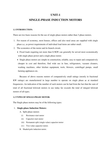
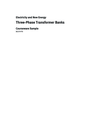
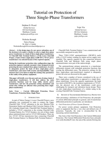
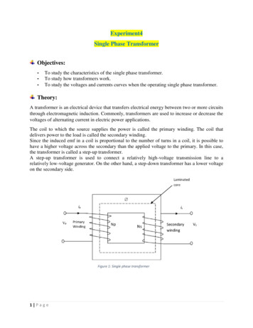
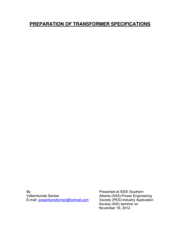
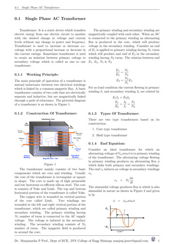
0.1. Single Phase AC Transformer0.1Single Phase AC TransformerTransformer: It is a static device which transferselectric energy from one electric circuit to anotherwith the desired change in voltage and currentlevels without any change in power and frequency.Transformer is used to increase or decrease a.c.voltage with a proportional increase or decrease inthe current ratings. Sometimes transformer is usedto create an isolation between primary voltage tosecondary voltage which is called as one to onetransformer.0.1.1The primary winding and secondary winding aremagnetically coupled with each other. When an ACis connected to the primary winding an alternatingflux is produced in the core, which will producevoltage in the secondary winding. Consider an emfof E1 is applied to primary winding having N1 turnswhich will produce and emf of E2 in the secondarywinding having N2 turns. The relation between emfE1 , E2 , N1 is N2E1N1 E2N2N2E2 E1N1Working Principle:The main principle of operation of a transformer ismutual inductance between two electrical windingswhich is linked by a common magnetic flux. A basic For no load condition the current flowing in primarytransformer consists of two coils that are electrically winding I1 and secondary winding I2 are related byseparate and inductive, but are magnetically linkedE1 I1 E2 I2through a path of reluctance. The pictorial diagramE1I2N1 of a transformer is as shown in Figure 1.E2I1N20.1.2Construction Of Transformer:0.1.3Types Of Transformer:There are two type transformers based on itsconstruction:1. Core type transformer2. Shell type transformer0.1.4Emf Equation:Consider an ideal transformer for which analternating voltage of Vm sinωt is to primary windingof the transformer. The alternating voltage flowingin primary winding produces an alternating flux φFigure 1which links both primary and secondary windings.The transformer mainly consists of two basic The emf e1 induces an voltage in secondary windingscomponents which are core and winding. Usually e2 .the core of the transformer is rectangular or squaredφe1 N1in shape. The core is made up of high permeabledtand low hysteresis co-efficient silicon steel. The coreThe sinusoidal voltage produces flux is which is alsois consists of Yoke and Limb. The top and bottomsinusoidal in nature as shown in Figure 2 and givenhorizontal portion of the transformer is called Yoke.is byThe copper wire is wounded on vertical portionof the core called Limb.Two windings areφ φm sinωtwounded at the left and right vertical portion of the mtransformer, which are called primary winding andTsecondary winding. The primary winding having2N1 number of turns is connected to the AC supplyTTvoltage. The voltage is induced in the secondary2winding. The secondary winding consists of N2 mnumber of turns. The magnetic field is producedCycle Tin around the core.Dr. Manjunatha P Prof., Dept of ECE, JNN College of Engg Shimoga manjup.jnnce@gmail.com1
0.1. Single Phase AC TransformerFigure 2dφdtdφm sinωt N1dt N1 φm cosωt ωe N1 2πf N1 φm cosωt 2πf N1 φm sin(ωt 90 ) 2πf N1 φmThe rms value of the induced emf isEm12πf N1 φm 22 4.4πf φm N1E1 Due to the induced emf there is a currentcalled the eddy current which is beingcirculated in the core. Due to the presence of some resistance in thecore the eddy current is converted into heatcalled the eddy current power loss. Eddy current loss is proportional to the squareof the supply frequency. Eddy current loss can be minimized by usingthe core made of thin sheets of silicon steelmaterial, and each lamination is coated withvarnish insulation to suppress the path of theeddy currents.Hysteresis loss (Wh ):Similarly induced emf in the secondary winding isE2E2E1Em12πf N2 φm 22 4.4πf φm N2 4.4πf φm N2N2 4.4πf φm N1N1 Eddy current loss occurs in the iron core, dueto the magnetic reversal of the flux in the core,which results in the form of heat in the core. This loss is directly proportional to the supplyfrequency. Hysteresis loss can be minimized by using thecore material having high permeability.OrE1N10.1.5 E2N2Losses in a transformer:There are two types of power losses occurs in atransformer1. Iron losses2. Copper losses0.1.6Iron loss Pi :0.1.7Copper loss Pcu ): This is the power loss that occurs inthe primary and secondary coils when thetransformer is on load. This power is wasted in the form of heat dueto the resistance of the coils. This loss is proportional to the sequence of theload hence it is called the Variable loss whereas the Iron loss is called as the Constant loss asthe supply voltage and frequency are constantsIron loss is the power loss that occurs in the iron part Total losses of the transformer arethe transformer. Iron loss is depends on alternatingfrequency of the emf. The Iron losses are called as Pi Pcuthe constant losses. There are two types Iron lossthose are.Efficiency: Eddy current lossEfficiency is the ratio of the output power to theinput power of a transformer. It is defined as: Hysteresis lossEddy current loss (We ):η output powerinput power This is power loss which is due to the Input poweralternating flux linking the core, which willinduces an emf.Input power output power Iron loss Copper lossDr. Manjunatha P Prof., Dept of ECE, JNN College of Engg Shimoga manjup.jnnce@gmail.com2
0.1. Single Phase AC Transformerη output powerinput poweroutput poweroutput power Iron loss Copper lossV2 I2 cosφV2 I2 cosφ WIron WCopperCondition For Maximum Efficiency:η output powerinput poweroutput poweroutput power Iron loss Copper lossV2 I2 cosφ V2 I2 cosφ Pi I22 R2cV2 I2 cosφ V2 cosφη 1 PiI2 R2c Where, V2 is the transformer output voltage, I2 isthe output current and cosφ is the power factor ofthe load.The condition for maximum efficiency isThe transformers are specified with KVA ratingsdη 0dI2η KV A(103 ) cosφKV A(103 ) cosφ Pi PCuThe efficiency at any load and p.f is given bydηdI2V2 cosφPiV2 cosφ V2 cosφ 2 0PiI2 R2cV2 cosφI22 R2c 0 Pi I22 R2cη x kV A 1000 p.f.x kV A 1000 p.f. Wi x2 WCuThe condition for maximum efficiency of atransformer isPi I22 R2cwhere x is the load condition.Iron loss Copper lossDr. Manjunatha P Prof., Dept of ECE, JNN College of Engg Shimoga manjup.jnnce@gmail.com3
0.2. Problems on Transformer0.2Problems on TransformerQ1) A 50 kVA, 3300/330 V, single phase transformer Also determine primary and secondary currents onhas iron loss and full load copper loss 400 W and 600 full load.W respectively. Calculate the efficiency at half full Solution:load and 0.9 p.f. Also calculate the load at whichthe efficiency is maximumvoltage/turn 4.44f φmSolution: The efficiency at any load and p.f is given 4.44 50 0.05 11.1Vbyx kV A 1000 p.f.x kV A 1000 p.f. Wi x2 WCu0.5 50 1000 0.9 0.5 50 1000 0.9 400 0.52 600 0.976Number of turns in primary is 97.6%Number of turns in secondary isη Load at which the maximum efficiency issIron loss F ull load kV AF ull load copper lossr400 50600 40.823 kV A6000 540.511.1' 541N1 250 22.511.1' 23N2 Primary current isI1 25 103 4.167 A6000Secondary current is25 103Q2) In a 25 kVA, 2000/200 V, s transformer has 100 AI1 250iron loss and full load copper loss 350 W and 400 Wrespectively. Calculate the efficiency at UPF at half2020-Jan 5 b) A 40 kVA, single phase transformerand 34 th full load.has core loss 450 W and full load copper loss 850Solution:Watts. If the power factor of the load is 0.8i) At half load with UPF The efficiency at any Calculate:load and p.f is given byi) full load efficiencyx kV A 1000 p.f.η ii) maximum efficiency at UPFx kV A 1000 p.f. Wi x2 WCu0.5 25 1000 1iii) load for maximum efficiency 0.5 25 1000 1 350 0.52 400Solution: i) full load efficiency 0.9652 96.52%i) At 43 th load with UPFThe efficiency at any load and p.f is given byx kV A 1000 p.f.x kV A 1000 p.f. Wi x2 WCu0.75 25 1000 1 0.75 25 1000 1 350 (.75)2 400 0.9702η 97.02%Q3) The no load ratio of a 50 Hz 25 kVA, 6000/250V. Determine the number of turns on each of thewindings if the maximum flux in the core is 0.05 Wb.x kV A 1000 p.f.x kV A 1000 p.f. Wi x2 WCu1 40 1000 0.8 1 40 1000 0.8 450 12 850 0.961η 96.1%ii) maximum efficiency at UPFx kV A 1000 p.f.x kV A 1000 p.f. Wi x2 WCu1 40 1000 1 1 40 1000 1 450 12 850 0.968η 96.8%Dr. Manjunatha P Prof., Dept of ECE, JNN College of Engg Shimoga manjup.jnnce@gmail.com4
0.2. Problems on Transformeriii) Load at which the maximum efficiency issIron loss F ull load kV AF ull load copper lossr450 40850 29.104 kV A500000 Wi WCuWi WCu 43478.9η 2019-June 5 c) A 250 kVA, 11000/415 volts 50Hz transformer has 80 turns on the secondary.Calculate i)Rated primary and secondary currentsii) Number of primary turns iii) Maximum valueof flux in the core iv)Voltage induced /turn onsecondary (1)x kV A 1000 p.f.x kV A 1000 p.f. Wi x2 WCu0.5 500 1000 0.90.5 500 1000 0.9 Wi 0.52 WCu2250000.92 244565.21225000 Wi 0.52 WCu 225000 Wi 0.25WCuSolution:Wi 0.25WCu 19565.21i)Rated primary and secondary currentsE1 I1 rated kV A 1000250 1000I1 22.72A11000E2 I2 rated kV A 1000250 1000I2 602.4A4155000000.92 543478.9500000 Wi WCu (2)Solving 1 and 2Wi WCu 43478.9Wi 0.25WCu 19565.210.75WCu 23912.68WCu 31883.57Wi 11594.23ii) Number of primary turnsE2N2 E1N111000 80E1 N2N1 E2415 2120iii)Maximum value of fluxE2 4.44f φm N2415 23.36mW bφm 4.44 50 80iv)Voltage induced /turn on secondaryV oltage in secondaryN umber pf turn onsecondary415 5.18V80 2019-June 6 a) A 500 kVA, single phase transformerhas efficiency of 92% at full load unity p.f. and athalf load 0.9 p.f. Determine its efficiency at 80% ofthe full load and 0.95 p.f.Solution:x kV A 1000 p.f.x kV A 1000 p.f. Wi x2 WCu0.8 500 103 0.95 .8 500 103 0.95 11594.23 .82 31883.57 0.9223η 92.23%2020-Jan 9 c) (2017 Scheme) A 200 kVA,10000/400V 50 Hz single phase transformer has 200turns on the secondary. Calculate i) Primary andsecondary currents ii) Number of Primary turns iii)Maximum value of flux iv) Flux density at area 18cm2 .Solution:N1 ?, N2 200 E1 10000E2 400? I1 ? I2 ? φm ?ii) Primary and secondary currentsi) full load efficiencyη 0.92 x kV A 1000 p.f.x kV A 1000 p.f. Wi x2 WCu1 500 1000 11 500 1000 1 Wi 1 WCu200 103 20 A10000200 103I2 500 A400I1 Dr. Manjunatha P Prof., Dept of ECE, JNN College of Engg Shimoga manjup.jnnce@gmail.com5
0.2. Problems on TransformeriI) Number of Primary turnsE1N1 N2E2N110000 200400N1 25 200 5000full load primary and secondary currents iii) the fluxdensity in the core if the cross section of the core 60cm2Solution:N1 200, N2 50 E1 230E2 ? I1 ? I2 ? φm ?iii) Maximum value of fluxE1 4.44f φm N1E1φm 4.44f N110000φm 4.44 50 5000 9 10 3 W bi) no load secondary emfN1E1 E2N2N2N150E2 230 200 57.5E2 E1 iv) Flux density at area 18 cm2 .φmBmφm9 10 3 A18 4 5 10 W b/cm2Area A Bmii) Primary and secondary currents25 103 108.7 A23025 103 434.78 AI2 57.5I1 2020-Jan 10 c) (2017 Scheme) In a 25 kVA, 2000/200the flux density in the core if the cross section ofV transformer has iron loss and full load copperthecore 60 cm2loss 350 W and 400 W respectively. Calculate theiii) Maximum value of fluxefficiency at UPF on i) Full load ii) half full load.Solution:i) Full load with UPFThe efficiency at any load and p.f is given byx kV A 103 p.f.x kV A 103 p.f. Wi x2 WCu1 25 103 1 1 25 103 1 350 12 400 0.9708η E1 4.44f φm N1E1φm 4.44f N1230φm 4.44 50 200 5.18 10 3 W biv) Flux density at area 60 cm2 . 97.08%i) At half load with UPFThe efficiency at any load and p.f is given byx kV A 103 p.f.η x kV A 103 p.f. Wi x2 WCu0.5 25 103 1 0.5 25 103 1 350 0.52 400 0.9652φmBmφm5.18 10 3 A60 0.863 10 6 W b/cm2Area A Bm2019-June 10 b) (2017 Scheme) A transformer israted at 100 kVA. At full load its copper loss is 1200W and iron loss 960 W Calculate i)the efficiency of 96.52%full load at UPF ii) the efficiency at half load 0.8p.f. iii)The load KVA at which maximum efficiency2019-June 10 b) (2017 Scheme) The primaryoccurs iv) Maximum efficiency at 0.85 p.f.winding of a 25 KVA transformer has 200 turns andis connected to 230 V 50 Hz supply. The secondary Solution:turns are 50. Calculate i) no load secondary emf ii)i) Full load with UPFDr. Manjunatha P Prof., Dept of ECE, JNN College of Engg Shimoga manjup.jnnce@gmail.com6
0.2. Problems on TransformerThe efficiency at any load and p.f is given byx kV A 103 p.f.x kV A 103 p.f. Wi x2 WCu1 100 103 1 1 100 103 1 960 12 1200 0.9788ii) approximate values of the primary andsecondary currentsη 97.88%50 103 22.72 A220050 103I2 33.92 A1474I1 iii) Maximum value of flux densityii) the efficiency at half load 0.8 p.f.The efficiency at any load and p.f is given byE1 4.44f φm N1E1φm 4.44f N12200φm 4.44 50 300 0.033x kV A 103 p.f.x kV A 103 p.f. Wi x2 WCu0.5 100 103 0.8 0.5 100 103 0.8 960 0.52 1200 0.9694η 2019-Jan 5 b) A 400 kVA, single phase transformerhas a core loss of 2 kW and maximum efficiency atiii)The load KVA at which maximum efficiency 0.8 p.f. occurs when the load is 240 kW. Calculateoccursi) maximum efficiency at unity power factor ii) therefficiency on full load at 0.71 power factor .WiX F ull Load KV A Solution:F ull Load Cur960r (100 103 )1200WiX F ull Load KV A 89.443 KV AF ull Load Cur2iv) Maximum efficiency at 0.85 p.f.240 (400 0.8)F ull Load Cux kV A 103 p.f.η rx kV A 103 p.f. Wi x2 WCu2240 0.751 89.443 103 0.85F ull Load Cu320 1 89.443 103 0.85 960 12 12002 (0.75)2 0.5625 0.9723F ull Load C 96.94%u 97.23%2019-Jan 5 b) A 50 kVA, single phase transformerhas primary and secondary turns of 300 and 20respectively. The primary winding is connected to2200 V 50 Hz. Calculate i) No load secondaryvoltage ii) approximate values of the primary andsecondary currents on full load. iii) Maximum valueof flux density.F ull Load Cu 2 3.555 kW0.5625x kV A 1000 p.f.x kV A 1000 p.f. Wi x2 WCu1 240 1000 1 1 240 1000 1 2 12 2 0.9836η 98.36%Solution:N1 300, N2 20 E1 2200E2 ? I1 ? I2 ? φm ?i) No load secondary voltageE2N2E220 E1N12200300E2 0.067 2200 146.6 Vx kV A 1000 p.f.x kV A 1000 p.f. Wi x2 WCu1 400 1000 0.71 1 400 1000 0.71 2 12 3.555 0.9808η 98.08%2019-Jan 10 c) (2017 -scheme) The maximumefficiency at full load and unity p.f. of a singleDr. Manjunatha P Prof., Dept of ECE, JNN College of Engg Shimoga manjup.jnnce@gmail.com7
0.2. Problems on Transformerphase 25 kVA, 500/1000V 50 Hz transformer is 98%.Determine its efficiency at i) 75% load 0.9 p.f. ii)50% load 0.8 p.f.iii) Maximum value of fluxE1 4.44f φm N1E1φm 4.44f N16000φm 4.44 50 1500 18.01 10 3 W bSolution:Maximum efficiency occurs when Wi WCux kV A 1000 p.f.η x kV A 1000 p.f. Wi x2 WCu1 25 103 10.98 1 25 103 1 Wi 12 WCu1031 25 0.98 25510.225 103 Wi 1WCu 12019-June 10 c) (2015 Scheme) A 600 kVA, singlephase transformer has efficiency of 92% at full loadunity p.f. and at half load 0.9 p.f. Determine itsefficiency at 75% of the full load and 0.9 p.f.Wi WCu 25510.2 25 103 510.2 Solution:i) full load efficiency2Wi 25510.2 25 103 510.2x kV A 1000 p.f.Wi WCu 255.10η x kV A 1000 p.f. Wi x2 WCui) 75% load 0.9 p.f.1 600 103 10.92 0.75 25 103 0.91 600 103 1 Wi 1 WCuη 0.75 25 103 0.9 255.1 (0.75)2 255.1 0.9769600 103600 103 Wi WCu 97.69%0.92600 103 Wi WCu 652173.9ii) 50% load 0.8 p.f.Wi WCu 52173.39(3)0.5 25 103 0.80.5 25 103 0.8 255.1 (0.5)2 255.1 0.969η η 96.9% 2019-June 9 b) (2015 Scheme) A 100 KVA6000/400V 50 Hz single phase transformer has 100turns in the the secondary. Find i) full load primaryand secondary currents ii) number of turns in theprimary coil iii) maximum flux in the coreSolution:x kV A 1000 p.f.x kV A 1000 p.f. Wi x2 WCu0.5 600 103 0.90.5 600 103 0.9 Wi 0.52 WCu2700000.92 293478.26270000 Wi 0.52 WCu 270000 Wi 0.25WCuWi 0.25WCu 23478.26(4)Solving 3 and 4N1 ?, N2 100 E1 6000E2 400 I1 ? I2 ? φm ?Wi WCu 52173.9Wi 0.25WCu 23478.26i) Primary and secondary currents0.75WCu 28695.64WCu 38260.87100 103I1 16.67 AWi 139136000100 103I2 250 A400x kV A 1000 p.f.the flux density in the core if the cross section of η x kVA 1000 p.f. Wi x2 WCu2the core 60 cm0.75 600 103 0.9i) number of turns in the primary coil .75 600 103 0.9 13913 .752 38260.87E1N1 0.9210E2N2 92.10%E1N1 N2E2Dr. Manjunatha P Prof., Dept6000of ECE, JNN College of Engg Shimoga manjup.jnnce@gmail.com8 100
0.1. Single Phase AC Transformer 0.1 Single Phase AC Transformer Transformer: It is a static device which transfers electric energy from one electric circuit to another with the desired change in voltage and current levels without any change in power and frequency.