Transcription
Copyright by Polyga Inc. All rights reserved.Reproduction in whole or in part in any way without written permission from Polyga is strictly prohibited.This manual is furnished for informational use only, and is subject to change without notice. Polyga assumes noresponsibility or liability for any errors or inaccuracies that may appear in this document.For additional information please contact support@polyga.com
Table of ContentsTable of Contents2IntroductionIntended AudienceSystem Requirements333Quick Start4Xtract3D FundamentalsConceptsFile Import/ExportImportExport MeshMesh InfoEdit MeshMesh ProcessingMove MeshOrient MeshAlign Mesh to SolidsCreate EntityCreate PlaneCross Section EntityDrafting and ModelingSliceSnapFitProjectPoint Cloud Data ProcessingHide All MeshesHide SolidsClip PCD SphereClip PCD CubeMesh 020212121222222242425Page 2
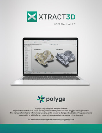
IntroductionXTract3D is a reverse engineering toolbar that works natively inside SOLIDWORKS.There is no need to create CAD models from scratch. XTract3D gives you powerfulslicing, fitting, and snapping tools to create parametric CAD simply by tracing right ontop of 2D cross sections of 3D scan data (Scan-to-CAD).Intended AudienceThis document is for new Xtract3D users. In this document, the concepts and designprocess for reverse engineering will be introduced in a high-level approach. Onlinevideo tutorials contain a comprehensive set of tutorials that provide step-by-stepinstructions on the features of Xtract3D including many samples.Online tutorials can be accessed here: Xtract3D Video Tutorials (Approximately 20minutes)System RequirementsRecommended Requirements Windows 10 64bit SOLIDWORKS 2022 12 GB of RAMMinimum Requirements Windows 10 64bit SOLIDWORKS 2015 8 GB of RAMPage 3
Quick Start1. Import the mesh data into SolidWorks through the Xtract3D import function.Scan samples can be found here: Scan Samples2. If the object does not align with the original coordinate system, create a newcoordinate system based on the mesh data. It makes it easier to make CADmodels out of the part in later steps.Page 4
Create a new plane by using the Slice function to cut the mesh. Then the 2Dcross-section of the part can be viewed.Page 5
3. Sketch the contour of the scan data outline using XTract3D and SolidWorksdrafting tools.4. Revolve the sketch to get the final CAD model.Page 6
Xtract3D FundamentalsConceptsXtract3D supports quickly importing high resolution Mesh and Point Cloud Data. It is anative SolidWorks add-in toolbar which allows users to perform the reverse engineeringprocess easily within a familiar environment in SolidWorks. XTract3D focuses onproviding a basic yet powerful set of tools to manually extract features, sketch, andcreate CAD data using the 3D scan data as a template for design.File Import/ExportImportThe file formats supported are shown below: Supported Mesh Files:.stl, .ply, .obj Supported Point Cloud Files: .ply, .e57, .asc, .csv, .pts, .txt, .laz, .lasPage 7
In the pop-up menu of importing mesh, users can set up correct file units and choose toplace the Mesh or Point Cloud Data in the global origin. It is recommended to minimizethe size of the imported data for the best rendering experience. In addition, theGenerate Normals function will generate facing information that enables better 3drendering of both point clouds and meshes.Export MeshAllow users to export the current mesh data and save on the local drive.Mesh InfoPage 8
Display Mesh and Point cloud data information. Allow users to change the rendersettings.Under the Mesh Info tab, users can change the render styles including Wireframe,Wiremesh and hide mesh option as well as change the color of the mesh. Users cantoggle on Render Normals if the Point Cloud Data has the feature. Generate Normalsallows users to generate facing information that enables better 3d rendering of bothpoint clouds and meshes.Edit MeshUnder the Edit Mesh tab, users can edit the mesh either by deleting selected areas orby decimating. This function is only available to mesh data. Decimate Mesh allowsusers to decimate the original mesh date by percentage, from 10% to 99%, in terms ofthe values of vertices and faces.Page 9
Mesh ProcessingPage 10
Move MeshUnder the Move Mesh Tab, users can translate and rotate the mesh by enteringnumbers into the boxes with correct units, including in, ft, um, mm, cm, m, and km. Themesh can also be reset to its origin by clicking the Auto Center Mesh button.Orient MeshUnder the Orient Mesh tab, users can change the orientation of the mesh/point clouddata by using selected points or planes.Page 11
Use Coordinate System:Align mesh data to the existing coordinate system. It is recommended to align the meshposition correctly into the SolidWorks coordinate system before starting the drafting andmodeling process.A detailed tutorial can be found here: Use Coordinate SystemAlign Mesh to SolidsPage 12
Aligns Mesh data to already created Solid files. Note: The Fine Alignment option shouldwork without having to use rough Alignment unless dealing with complex assembliesinvolving multiple part files or if the mesh and solid are not close to each other.For Aligning mesh to Solids:1. Click Set Three Mesh Points and select three points on the mesh surface.2. Click Set Three Solid Points and select three points on the surface of the solid.3. Click on Rough Alignment to roughly align both the entities.4. Lastly, Click on Fine alignment to perfectly align the mesh to the solid.Page 13
Create EntityCreate Entity allows users to create points, lines, splines, or centre points of a plane onMesh. Users can toggle creating the entities on either a new sketch or a selectedsketch.Create PlaneCreate a plane using selected points on the mesh, surface of the mesh, splines, or froman existing plane.Page 14
To create a plane, users can choose from the options in the dropdown menu, including3 points, single point, mesh select, use spline and copy plane. Users can also disablethe texture color based on their preference.Cross Section EntityCreate an intersecting plane that is perpendicular to the mesh.Page 15
For creating an intersecting plane:1. Click on Create First Plane and select points where the first reference plane is to becreated.2. Click on Create Second Plane and select points where the second reference plane isto be created.3. Click on Create Plane Center and select the point where you want to place theintersecting plane.4. Lastly, click on Create to create the plane that is perpendicular to the mesh.Page 16
Drafting and ModelingSliceCross-section slice of mesh/point cloud data at the intersection of a selected plane,face, section view, or stored slices.A detailed tutorial can be found here: SlicePage 17
Under the Slice tab, users can choose different methods to slice the mesh. It also allowsusers to generate multiple linear or circular slices by setting increments and number ofslices.Page 18
For point cloud data, users can define the width of the slice by changing SelectionWidth%.SnapUsers can snap points, lines, arcs, circles, or splines to the existing contour of the meshdata.FitUsers can fit lines, arcs, or circles to the existing contour of the mesh data afteraveraging it.Fitting an arc to mesh data:Page 19
1. Sketch on the slice plane with an arc. It is acceptable to deviate from the precisemodel.2. Select the arc and click FitProjectMoves 3D Points, lines, or splines to the closest surface.Point Cloud Data ProcessingHide All MeshesPage 20
Toggle the visibility of the Mesh or Point Cloud Data.Hide SolidsToggle the visibility of the Solids.Clip PCD SphereClips the point cloud data by using a spherical tool.Under the Clip PCD Sphere tab, users can define a sphere by setting the radius and thecenter. Reset allows users to undo all the changes made so far and start over.Page 21
Clip PCD CubeCreates a cubical shaped clipping tool for the point cloud data.For creating a cubic clipping tool:1. Setting Width: Click on Set Width and select two points that are far apart such thatyou decide the width of the cube.2. Setting Length: Click on Set Length and select another point in the point cloud thatdecides the length of the cube.3. Setting Depth: Click on Set Depth and similarly select another point that decides thewidth of the cube.4. Adjust the size of the cube by incrementing or decrementing the cube planes.Page 22
After selecting the desired size of data, users can choose to clip the point cloud datainto defined shape and size by using Clip Volume, or delete the unselected data byusing Delete Clipped Points (Note: Cannot revert any of the deleted points).Mesh DeviationCompare mesh data to CAD model and visualize the differences at different points.Users can change the color by adjusting bars on the top (CAD model color) and bars onthe bottom (mesh color), to have a better understanding of the deviation.Page 23
SettingsUnder the Settings tab, users can find the license and Xtract3D update information, andoptions to export CAD as mesh and sync broken meshes. It is recommended for allusers to update the Xtract3D to the latest version in order to get better performance.Details for each version can be found in Patch Notes and the latest version can bedownloaded following the Check for Updates. In addition, users can change the defaultsetting including render preference, mesh texture color and line width, point cloud datapreference and import options. If there is an issue rendering mesh files that are smallerthan 1 GB, users can toggle on Basic Rendering to switch back to the legacy renderingsystem.LicenseNormally, users are asked to fill in license information while opening the SolidWorks. Ifthe prompt is closed, SolidWorks can still be opened without Xtract3D showing in thetoolbar. Users can go to Customize (SolidWorks) -- Xtract3D and check the box. Thenthe license prompt will be shown again to type in license information.The other way is to go to: C:\Program Files\Polyga\XTract3D\LicenseApp.exe and typein license information.Users can change license information if multiple licenses are owned, by usingLicensing.Page 24
Page 25
native SolidWorks add-in toolbar which allows users to perform the reverse engineering process easily within a familiar environment in SolidWorks. XTract3D focuses on providing a basic yet powerful set of tools to manually extract features, sketch, and create CAD data using the 3D scan data as a template for design.Fi l e I mp o r t/ E x p o r t