Transcription
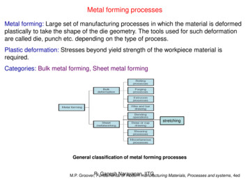
MODULE 5SHEET METAL OPERATIONS
SHEET METALWORKING
Cutting and forming thin sheets of metalusually performed as cold working Sheet metal 0.4 (1/64) to 6 mm (1/4in)thick Plate stock 6 mm thick Advantage - High strength, gooddimensional accuracy, good surface finish,economical mass production (low cost). Cutting, bending, drawing
PARTS MADE BY SHEET METAL FORMING Car bodies Aircraft fuselages Trailers Office furniture appliances Fuel tanks Cookware
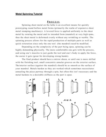
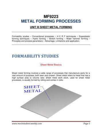
Sheet Metalworking Terminology“Punch-and-die”Tooling to perform cutting,bending, and drawing“Stamping press” Machine tool that performsmost sheet metal operations“Stampings”Sheet metal products
A set of die and punchPress working of sheet metal
SHEET METAL OPERATIONS SHEARING BLANKING PUNCHING (PIERCING) BENDING STAMPING DRAWING DEEP DRAWING EMBOSSING SPINNING ROLL FORMING
SHEET METAL CHARACTERISTICSCharacteristics of metals important in sheet forming1. Elongation2. Yield point elongation3. AnisotropyCrystallographic anisotropyMechanical fibering4. Grain Size5. Residual stresses6. Spring back7. Wrinkling8. Quality of sheared edges9. Surface condition of sheet
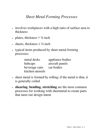
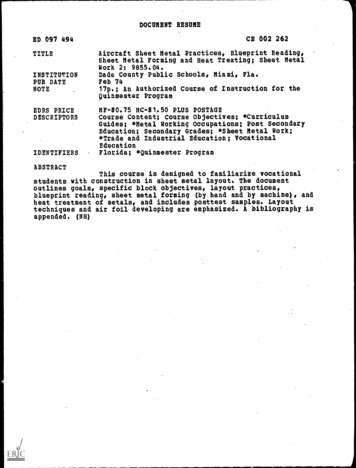
Cutting Operation Shearing - using a machine called power shear orsquare shear. Blanking – shearing a closed outline (desired partcalled blank) Punching – sheared part is slag (or scrap) andremaining stock is a desired part
CUTTING OPERATION
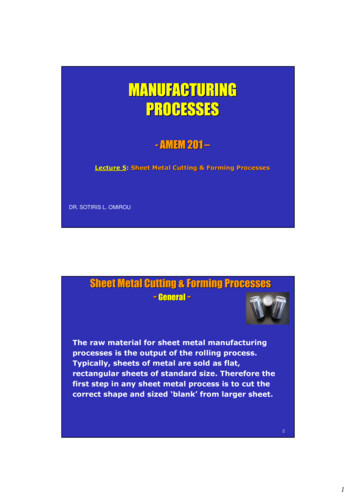
SHEARING
AnalysisClearance -4-8% but sometime 1% of thicknessToo small –fracture does not occur requiring more force.Too large –Get pinched and cause an excessive burrClearance: c a*tMetal group 1100S and 5052S aluminum alloys, all tempers2024ST and 6061ST aluminum alloys; brass, soft cold rolled steel, soft stainless steel Cold rolled steel, half hard; stainless steel, half hardand full harda0.0450.0600.075
Factors affecting shearing operation Shape and material of the punch Die, speed of punching, lubrication Clearance between punch & die
Die, blank and punch size For a round blank,Blank punch diameter Db-2cBlank die diameter Db For a round hole,Hole punch diameter DhHole die diameter Dh 2c Angular clearance of 0.25 to 1.5 Cutting forces: F S t L 0.7 TS t Lwhere S Shear strengtht thicknessL length of cutting edgeTS Ultimate tensile strength
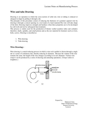
STAGES IN SHEARING ACTION1. Plastic Deformation2. Fracture3. Shear
FEATURES OF PUNCHED HOLE
FEATURES OF SLUG
Blanking punch and die
Other Cutting Operations
LANCING OPERATION
Maximum force, P required to be exerted by thepunch to shear out a blank from the sheet can beestimated asP t.L.τt – Sheet thicknessL – Total length shearedτ - Shear strength of the sheet material
Shearing force, SF 0.02 LtSF – Shearing force in KNL – Length of cut in mmt – Thickness of material in mm
Clearance between die and punch,c 0.003t.τ
τ
PROGRESSIVE AND COMPOUND DIES
PROGRESSIVE DIE
COMPOUND DIE
Forming-Limit DiagramA grid pattern of circles, typically 2.5 to 5mm indiameter, produced by electrochemical orphotoprinting.After drawing, the circles are observed for failure.The major strain is on the major direction andmagnitude of strain
Bending Operations
In V-bending, the sheet metal is bent between aV-shaped punch and die set up. The includedangles range from very obtuse to very acutevalues.
In edge bending, cantilever loading of the sheet isseen. A pressure pad is used to apply a force tohold the sheet against the die, while the punchforces the sheet to yield and bend over the edgeof the die.
Other Bending Operations FlangingHemmingSeamingCurlingChannel, U-bendingOffset bending,and Tube formingAir bending,Corrugating
BENDING OPERATION
Sheet bendingSheet bending is defined as the straining of themetal around a straight axis.During bending operation, the metal on the inner sideof the neutral plane is compressed, and the metal onthe outer side of the neutral plane is stretched.Bending causes no change in the thickness of the sheetmetal.
SPRING BACKAt the end of the bending operation, the bent part retains some ofits elasticity which is recovered after the punch is removed.PREVENTING METHODS1. Stretch forming2. Overbending3. Bottoming4. Ironing
Drawing
Basic drawing operation –a cup-shape part
Detail Steps of Drawing
Detail Steps of Drawing .
Detail Steps of Drawing
Other Drawing Operation Redrawing Drawing without a Blankholder
Defects in drawing Wrinkling in the flange Wrinkling in the wall Tearing Earing –Anistropy in sheet metal Surface scratch
Wrinkling in flange and cup wall: This is like ups and downs orwaviness that is developed on the flange. If the flange is drawninto the die hole, it will be retained in cup wall region. Tearing: It is a crack in the cup, near the base, happening due tohigh tensile stresses causing thinning and failure of the metal atthis place. This can also occur due to sharp die corner. Earing: The height of the walls of drawn cups have peaks andvalleys called as earing. There may be more than four ears.Earing results from planar anisotropy (ΔR), and ear height andangular position correlate well with the angular variation of R. Surface scratches: Usage of rough punch, dies and poorlubrication cause scratches in a drawn cup.
Stretching/stretch formingStretch forming is a sheet metal forming processin which the sheet metal is intentionally stretched andsimultaneously bent to have the shape change.Sheet is held by jaws or drawbeads at both the ends andthen stretched by punch, such that the sheet is stressedabove yield strength.
When the tension is released, the metal has beenplastically deformed. The combined effect of stretchingand bending results in relatively less springback in thepart.
Stretching/stretchforming
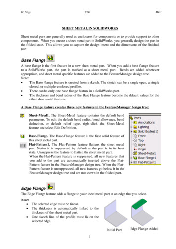
METAL SPINNINGMetal Spinning process is a cold formingprocess in which the blank metal appears toflow somewhat like a piece of clay on a potter'swheel.
PROCESS OF METAL SPINNINGExternal shape of the mandrel corresponds to theinternal contour of the part to be produced. The blank is clamped between spinning mandrel and afollower on the tailstock spindle. The mandrel, blank, and follower are then set in rotation atcontrolled speeds.
STEPS IN SPINNING PROCESSStep 1 : Metal Forming This step involves the laying down of the material onto themandrel. It is accomplished with short inside to outside moves. Material gets easier to form as the part is closer tocompletion
Step 2 : Trimming Parts having been spun are trimmedat the end to blunt sharp edges and also to bring thecomponent to the desired length.Step 3 : Finishing Finishing is done at very high RPMs (1200 ) so that aminimum of force need be applied and very smoothstrokes can be used. The flat side of spinning tool is used for straightsurfaces and rounded side for curves and radii.
Shear Spinning
TUBE SPINNING Thickness of cylindrical parts are reduced byspinning them on a cylindrical mandrel rollers Parts can be spun in either direction Large tensile elongation up to 2000 % are obtainedwithin certain temperature ranges and at low strainrates.
COMPARISON WITH OTHER FORMINGPROCESSES Low tooling cost compared to other formingtechniques. Conventional spinning also wastes a considerablysmaller amount of material than other methods . The standard method of press forming the partrequires many steps, as opposed to only three stepsfor spinning.
Rubber formingIn bending and embossing of sheet metal,the female die is replaced with rubber pad Rubberpadforming(RPF)isa metalworking process where sheet metal ispressed between a die and a rubber block,made of polyurethane. Under pressure, the rubber and sheet metalare driven into the die and conform to itsshape, forming the part.
Rubber pads can have a general purpose shape,like a membrane. Alternatively, they can be machinedin the shape of die or punch.
Rubber forming In bending and embossing of sheet metal, the female die is replaced with rubber pad Rubber pad forming (RPF) is a metalworking process where sheet metal is pressed between a die and a rubber block, made of polyurethane. Under pressure, the rubber and sheet metal are driven into the die and