Transcription
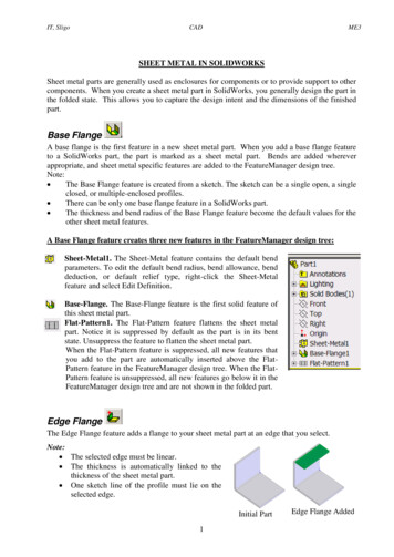
Lecture Notes on Manufacturing ProcessWire and tube DrawingDrawing is an operation in which the cross-section of solid rod, wire or tubing is reduced orchanged in shape by pulling it through a die.The principle of this procedure consist of reducing the thickness of a pointed ,tapered wire bydrawing it through a conical opening in a tool made of a hard material.The wire will take shapeof the hole. Drawing improves strength and hardness when these properties are to be developedby cold work and not by subsequent heat treatment.This process is widely used for the production of thicker walled seamless tubes and cylinderstherefore; shafts, spindles, and small pistons and as the raw material for fasteners such as rivets,bolts, screws. Drawing is classified as1. Wire drawing2. Tube drawingWire Drawing:Wire drawing is a metal-reducing process in which a wire rod is pulled or drawn through a singledie or a series of continuous dies, thereby reducing its diameter. Because the volume of the wireremains the same, the length of the wire changes according to its new diameter. Various wiretempers can be produced by a series of drawing and annealing operations. (Temper refers totoughness.)(a)Prepared by;Mahmood AlamDeptt. Of Mechanical Engg.Integral UniversityLucknow
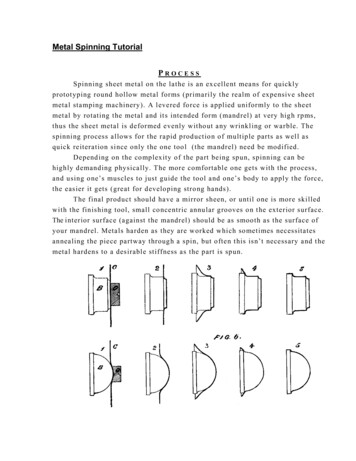
Lecture Notes on Manufacturing Process(b)(c)Figure-(a)Wire Drawing sectional view (b) wire drawing set up (c) Enlarge View of WireReductionProcess Characteristics Pulls a wire rod through a die, reducing its diameterIncreases the length of the wire as its diameter decreasesMay use several dies in succession (tandem) for obtaining small diameter wires.Improves material properties due to cold workingWire temper can be controlled by swaging, drawing, and annealing treatmentsTube DrawingWhen a hollow tube is drawn through a die, generally a mandrel or plug is used to support theinside diameter of the tube, this process is called tube drawing. The function of the plug is toeffect wall reduction and to control the size of the hole. However, the mandrel may be omitted ifit is not necessary to make a reduction in the wall thickness, or if the dimensions and surface ofthe inside are not important. The process to draw a pipe without any mandrel is known as tubesinking.In drawing tubes over a stationary mandrel, the maximum practical sectional area reduction doesnot exceed 40 per cent per pass due to the increased friction from the mandrel. If a carefullymatched mandrel floats in the throat of the die, it is possible to achieve a reduction in area of 45percent, and for the same reduction the drawing loads are lower than for drawing with a fixedplug. This style is called the drawing with floating plug. It is worth mentioning here that in thisstyle, the tool design and lubrication can be very critical. Problems with friction in tube drawingPrepared by;Mahmood AlamDeptt. Of Mechanical Engg.Integral UniversityLucknow
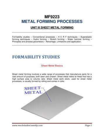
Lecture Notes on Manufacturing Processare minimized in drawing with a long mandrel. The mandrel consists of a long hard rod or wirethat extends over the entire length of the tube and is drawn through the die with the tube. In thisdesign, the area reduction can be 50 per cent. However, after drawing, the mandrel must beremoved from the tube by rolling (reeling), which increases the tube diameter slightly anddisturbs the dimensional tolerances. The drawing process discussed above has been illustrated inthe figure 2.18Figure-Tube drawing processes. (a) Sinking; (b) fixed plug; (c) floating plug; (d) movingmandrelDefects in drawing process:Figure (a) Wrinkling in the flange or (b) in the wall (c) tearing, (d) Earing, (e) surface scratchesBasic press working OperationSheet metal working is also a metal forming operation where the material being worked is in theform of sheets the working is usually at room temperature. The process is called the pressworking of sheet metal. For sheet metal working a set of die and punch assembly is normallyused to obtain various components from a sheet metal.Die and Punch assemblyPrepared by;Mahmood AlamDeptt. Of Mechanical Engg.Integral UniversityLucknow
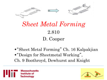
Lecture Notes on Manufacturing ProcessA simple die and punch assembly also called die-set is shown in figure. The parts of the die andpunch system are labeled. This assembly is mounted on press.Figure-Die and Punch AssemblyThe press supports a ram (slide) that holds a punch and a bed that holds the die in a die holderconnected to the bolster plate. In sheet metal working operation, the sheet thickness remainsalmost constant. The process has the following advantage:1. The part fabricated are light in weight2. High labour productivity3. High efficiency of the process4. Gives close toleranceThe important characteristic of the sheet material is its formability i.e. its ability to stretchuniformly (resistance to thinning). Various tests are available to assess the formability of sheet.Some problem arise out of sheet used being thin, such as spring back. Buckling, and wrinkling.A proper die design and minimizing the unsupported length during processing may solve theproblem.Cutting Process (sheet metal Working/ press working)A brief introduction of some important sheet- metal working operation is given below:Prepared by;Mahmood AlamDeptt. Of Mechanical Engg.Integral UniversityLucknow
Lecture Notes on Manufacturing Process1. Blanking and Punching: In these processes a finite shape of sheet metal is removed byshearing the entire contour using a die and a punch. If the portion removed is the requiredproduct, the operation is called Blanking and the product is called blank. On the contrary,if the pierced sheet is final product, the operation is termed as punching. A simpleblanking die and blanking operation is shown in figure. It is important to note that thepunch and die corners are sharp and not provided with any radius as the process need tocause a rupture of the material. A clearance c is provided on die in punching operationand the punch is to the required size. Hence die diameter Dd Dp 2c where Dp and Dd arethe die and punch diameter.Figure Blanking and (b) punching2. Shaving: The rough edges of a blanked part are removed by cutting (shearing) thin stripof metal along the edges on the periphery.3. Trimming: trimming is the operation of cutting and removing unwanted excess material(flash, etc) from the periphery of previously formed/forged/cast component.Prepared by;Mahmood AlamDeptt. Of Mechanical Engg.Integral UniversityLucknow
Lecture Notes on Manufacturing ProcessFigure (a) shaving and (b) trimming4. Notching: Notching is a cutting operation in which metal sheet, stripsor blank are cut(sheared) at the edge as shown in figure. Ting5. Perforating: perforating is a process used to make multiple holes which are small indiameter and close together, in flat work material.6. Slitting: Slitting refers to the operation of making incomplete holes from s slit (anopening) in the sheet metal as shown in figure.7. Lancing: Lancing is a operation of cutting on one side and bending on other side to forma sort of tab or louver.Figure (a) Notching, (b) Slitting, (c) Lancing and (d) Nibbling8. Parting: parting is a operation of shearing a sheet into two or more pieces.9. Nibbling: Nibbling is the operation used to punch overlapping small holes along acontour to cut out contoured parts from sheet metal. This operation is generally aPrepared by;Mahmood AlamDeptt. Of Mechanical Engg.Integral UniversityLucknow
Lecture Notes on Manufacturing Processsubstitute for blanking if the number of pieces required is small. The part is usuallyguided by hand continuously.10. Deep Drawing: This is also known as cup or radial drawing as it produces cup shapedobjects. Depth produced in deep drawing is more than the diameter. Shallow parts canalso be produced by this method. Typical products made by this process include domesticpots, pans, food container, automobile fuel tanks, etc. In deep drawing a flat sheet metalblank kept under a blank holder is forced into a die cavity by means of a punch. Force onblank holder should be sufficient to prevent wrinkling of sheet but should allow the blankto slide into the die cavity as it is drawn in.Figure- Deep drawing11. Bending: In bending operation the metal is stressed in both tension and compression atvalues below the ultimate strength of the material without appreciable change in itsthickness. In designing a rectangular section for bending, the material allowed for thebend must be determined, since the outer fiber are elongated and the inner onesshortened, the neutral axis of the section moves in towards the compression side whichthrows more of the fibers in tension. The total thickness is slightly decreased and widthincreased on the tension side and narrowed on the other. The bent part retains some of itselasticity which is recovered after the punch is removed as shown in figure. This isknown as spring back. Spring back may be corrected by over bending by an amount thatbrings the part to return to the correct shape.Prepared by;Mahmood AlamDeptt. Of Mechanical Engg.Integral UniversityLucknow
Lecture Notes on Manufacturing ProcessFigure-bending operationApplication of sheet- metal working:Sheet metal is widely used for numerous industrial and non-industrial applications including: Aircraft: Fuselages, wings, body panels, trim parts, etc.Automotive: body panels, bumpers, doors, chassis, trim parts, brackets etc.Construction: roofing, home building and structural applications.Other applications: appliances, food and beverage containers, boilers, kitchenequipment, office equipment etc.Defects in sheet- metal working:Defects in sheet-metal formed parts originated from the following basic sources:1. Defective raw materials (sheet-metal stock)2. Defective die- design3. Defective processing (forming) techniqueDefects due to raw materials and die-design can be tackled at source by purchasing quality rawmaterial and good design of die and checking its quality before starting production and takinginto consideration the factors affecting quality die design.Defects due to forming technique will be discussed with sketches in the following paragraph.Prepared by;Mahmood AlamDeptt. Of Mechanical Engg.Integral UniversityLucknow
Lecture Notes on Manufacturing Process1. Stretcher strain marks: During drawing or forming, as stretching begins, yielding islocalized in a thin visible band (luders’ lines). As stretching continues further, families of theselines criss-cross and deform on yielding.Figure-Stretcher strain marks2. Earing: Earing is a defect that occurs due to uneven drawing as shown in figure. To eliminate“Earing” excessive deformation in deep drawing should be avoided.Figure-Earing due to uneven drawing and part failure3. Orange peel effect: when a coarse grained material is drawn, the grain will manifestthemselves into a rough surface due to re crystallization in areas with maximum strain hardeningand not contact with die surface. This roughness resembles the surface of an orange peel.Figure -Orange and peel effect4. Sinking: sinking refers to small depression on the surface of a formed part. It gives rise tounbalanced internal stresses which may cause failure.Prepared by;Mahmood AlamDeptt. Of Mechanical Engg.Integral UniversityLucknow
Lecture Notes on Manufacturing Process5. Burr and Bend: Due to improper clearance burrs are formed on the cut edge at periphery.Figure- Burr and Bend due to excessive clearance6. Part failure: As shown in figure7. Strain hardening: Occurs when a metal is strained to plastically deform below recrytalizationtemperature (cold working). Strength and hardness increase and ductility reduced.8. Wrinkling: flanges and wall wrinkle due to lose punch/blank holder clearance as shown infigureFigure -Wrinkling on flanges and wall. Part failure may also occurPrepared by;Mahmood AlamDeptt. Of Mechanical Engg.Integral UniversityLucknow
Sheet metal working is also a metal forming operation where the material being worked is in the form of sheets the working is usually at room temperature. The process is called the press working of sheet metal. For sheet metal working a set of die and punch assembly is normally used to obtai