Transcription
Chapter 13Object-Oriented DataModelingLearning ObjectivesAfter studying this chapter, you should be able to: Concisely define each of the following key terms: class, object, state, behavior, classdiagram, object diagram, operation, encapsulation, constructor operation, queryoperation, update operation, class-scope operation, association, association role,multiplicity, association class, abstract class, concrete class, class-scope attribute,abstract operation, method, polymorphism, overriding, multiple classification,aggregation, and composition. Describe the activities in the different phases of the object-oriented developmentlife cycle. State the advantages of object-oriented modeling vis-à-vis structured approaches. Compare the object-oriented model with the E-R and EER models. Model a real-world domain by using a Unified Modeling Language (UML) classdiagram. Provide a snapshot of the detailed state of a system at a point in time, using a UMLobject diagram. Recognize when to use generalization, aggregation, and composition relationships. Specify different types of business rules in a class diagram.IntroductionIn Chapters 2 and 3, you learned about data modeling using the E-R and EER models.In those chapters, you discovered how to model the data needs of an organizationusing entities, attributes, and a wide variety of relationships. In this chapter, youwill be introduced to the object-oriented model, which is becoming increasinglypopular because of its ability to thoroughly represent complex relationships, aswell as to represent data and system behavior in a consistent, integrated notation.Fortunately, most of the concepts you learned in those chapters correspond toconcepts in object-oriented modeling. The object-oriented approach offers evenmore expressive power than the EER model.As you learned in Chapters 2 and 3, a data model is an abstraction of the realworld. It allows you to deal with the complexity inherent in a real-world problemby focusing on the essential and interesting features of the data an organizationneeds. An object-oriented model is built around objects, just as the E-R model isbuilt around entities. However, an object encapsulates both data and behavior,implying that we can use the object-oriented approach not only for data modeling,but also to model system behavior. To thoroughly represent any real-world system,13-1
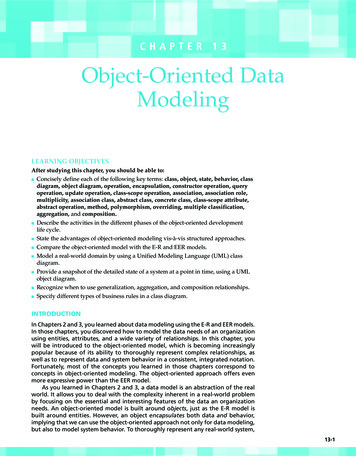
13-2Part V Advanced Database Topicsyou need to model both the data and the processes and behavior that act on thedata (recall the discussion in Chapter 1 about information planning objects). Byallowing you to capture them together within a common representation, and byoffering benefits such as inheritance and code reuse, the object-oriented modelingapproach provides a powerful environment for developing complex systems.The object-oriented systems development cycle, depicted in Figure 13-1, consistsof progressively and iteratively developing object representation through threephases—analysis, design, and implementation—similar to the heart of the systemsdevelopment life cycle explained in Chapter 1. In an iterative development model,the focus shifts from more abstract aspects of the development process (analysis)to the more concrete ones over the lifetime of a project. Thus, in the early stagesof development, the model you develop is abstract, focusing on external qualitiesof the system. As the model evolves, it becomes more and more detailed, the focusshifting to how the system will be built and how it should function. The emphasisin modeling should be on analysis and design, focusing on front-end conceptualissues rather than back-end implementation issues that unnecessarily restrictdesign choices (Larman, 2004).In the analysis phase, you develop a model of a real-world application, showingits important properties. The model abstracts concepts from the applicationdomain and describes what the intended system must do, rather than how it will bedone. It specifies the functional behavior of the system independent of concernsrelating to the environment in which it is to be finally implemented. You needto devote sufficient time to clearly understand the requirements of the problem,while remembering that in the iterative development models, analysis activitieswill be revisited multiple times during a development project so that you can applythe lessons learned from the early stage design and implementation activitiesto analysis. Please note that during the analysis activities, your focus should beon analyzing and modeling the real-world domain of interest, not the internalcharacteristics of the software system.In the object-oriented design phase, you define how the analysis model focusedon the real world will be realized in the implementation environment. Therefore,your focus will move to modeling the software system, which will be very stronglyinformed by the models that you created during the analysis activities. Jacobsonet al. (1992) cite three reasons for using object-oriented design:1. The analysis model is not formal enough to be implemented directly in a programming language. Moving seamlessly into the source code requires refiningthe objects by making decisions about what operations an object will provide,what the communication between objects should look like, what messagesare to be passed, and so forth.Figure 13-1 Phases of theobject-oriented systemsdevelopment cycleImplementationSystem Design- system architecture- subsystemsAnalysis- application- whatObject Design- programming- database access- data structures- algorithms- controls
Chapter 13 Object-Oriented Data Modeling2. The system must be adapted to the environment in which the system willactually be implemented. To accomplish that, the analysis model has to betransformed into a design model, considering different factors such as performance requirements, real-time requirements and concurrency, the targethardware and systems software, the DBMS and programming language to beadopted, and so forth.3. The analysis results can be validated using object-oriented design. At thisstage, you can verify whether the results from the analysis are appropriate forbuilding the system and make any necessary changes to the analysis modelduring the next iteration of the development cycle.To develop the design model, you must identify and investigate the consequencesthat the implementation environment will have on the design. All strategic designdecisions, such as how the DBMS is to be incorporated, how process communicationsand error handling are to be achieved, what component libraries are to be reused, andso on are made. Next, you incorporate those decisions into a first-cut design model thatadapts to the implementation environment. Finally, you formalize the design modelto describe how the objects interact with one another for each conceivable scenario.Within each iteration, the design activities are followed by implementationactivities (i.e., implementing the design using a programming language and/ora database management system). If the design was done well, translating it intoprogram code is a relatively straightforward process, given that the design modelalready incorporates the nuances of the programming language and the DBMS.Coad and Yourdon (1991) identify several motivations and benefits of objectoriented modeling: The ability to tackle more challenging problem domainsImproved communication among the users, analysts, designers, and programmersIncreased consistency among analysis, design, and programming activitiesExplicit representation of commonality among system componentsRobustness of systemsReusability of analysis, design, and programming resultsIncreased consistency among all the models developed during object-orientedanalysis, design, and programmingThe last point needs further elaboration. In other modeling approaches, suchas structured analysis and design (described in Chapter 1), the models that aredeveloped lack a common underlying representation and, therefore, are very weaklyconnected. For example, there is no well-defined underlying conceptual structurelinking data flow diagrams used for analysis and structure charts used for designin traditional structured analysis and design. In contrast to the abrupt and disjointtransitions that the earlier approaches suffer from, the object-oriented approachprovides a continuum of representation from analysis to design to implementation,engendering a seamless transition from one model to another. For instance, theobject-oriented analysis model is typically used almost directly as a foundation forthe object-oriented design model instead of developing a whole new representation.In this chapter, we present object-oriented data modeling as a high-levelconceptual activity. As you will learn in Chapter 14, a good conceptual model isinvaluable for designing and implementing an object-oriented application thatuses a relational database for providing persistence for the objects.Unified Modeling LanguageUnified Modeling Language (UML) is a set of graphical notations backed by a commonmetamodel that is widely used both for business modeling and for specifying, designing,and implementing software systems artifacts. It culminated from the efforts of three leading experts, Grady Booch, Ivar Jacobson, and James Rumbaugh, who defined this objectoriented modeling language that has become an industry standard. UML builds upon andunifies the semantics and notations of the Booch (Booch, 1994), OOSE (Jacobson et al., 1992),13-3
13-4Part V Advanced Database Topicsand OMT (Rumbaugh et al., 1991) methods, as well as those of other leading methods.UML has recently been updated to UML 2.4, maintained by the Object Management Group.UML notation is useful for graphically depicting object-oriented analysis and design models. It not only allows you to specify the requirements of a system and capture the design decisions; in addition, it also promotes communication among key persons involved in thedevelopment effort. A developer can use an analysis or design model expressed in the UMLnotation as a means to communicate with domain experts, users, and other stakeholders.To represent a complex system effectively, the model you develop must consistof a set of independent views or perspectives. UML allows you to represent multipleperspectives of a system by providing different types of graphical diagrams, such asthe use-case diagram, class diagram, state diagram, sequence diagram, component diagram, and deployment diagram. If these diagrams are used correctly together in thecontext of a well-defined modeling process, UML allows you to analyze, design, andimplement a system based on one consistent conceptual model.Because this text is about databases, we will describe only the class diagram, which is oneof the static diagrams in UML, addressing primarily structural characteristics of the domainof interest. The class diagram allows us also to capture the responsibilities that classes canperform, without any specifics of the behaviors. We will not describe the other diagram typesbecause they provide perspectives that are not directly related to database systems. Keep inmind that a database system is usually part of an overall system, whose underlying modelshould encompass all the different perspectives. For a discussion of other UML diagrams,see Hoffer et al. (2011) and George et al. (2007). It is important to note that the UML class diagrams can be used for multiple purposes at various stages of the life cycle model.Object-Oriented Data ModelingIn this section, we introduce you to object-oriented data modeling. We describe themain concepts and techniques involved in object-oriented modeling, including objectsand classes; encapsulation of attributes and operations; association, generalization, and aggregation relationships; cardinalities and other types of constraints; polymorphism;and inheritance. We show how you can develop class diagrams, using the UML notation,to provide a conceptual view of the system being modeled.Representing Objects and ClassesClassAn entity type that has a well-definedrole in the application domain aboutwhich the organization wishes tomaintain state, behavior, and identity.ObjectAn instance of a class thatencapsulates data and behavior.StateAn object’s properties (attributesand relationships) and the valuesthose properties have.BehaviorThe way in which an object actsand reacts.In the object-oriented approach, we model the world in objects. Before applying the approachto a real-world problem, therefore, we need to understand what an object and some relatedconcepts really are. A class is an entity type that has a well-defined role in the applicationdomain about which the organization wishes to maintain state, behavior, and identity. Aclass is a concept, an abstraction, or a thing that makes sense and matters in an applicationcontext (Blaha and Rumbaugh, 2005). A class could represent a tangible or visible entitytype (e.g., a person, place, or thing); it could be a concept or an event (e.g., Department,Performance, Marriage, Registration); or it could be an artifact of the design process (e.g.,User Interface, Controller, Scheduler). An object is an instance of a class (e.g., a particularperson, place, or thing) that encapsulates the data and behavior we need to maintain aboutthat object. A class of objects shares a common set of attributes and behaviors.You might be wondering how classes and objects are different from entity typesand entity instances in the E-R and EER models you studied in Chapters 2 and 3.Clearly, entity types in the E-R model can be represented as classes and entity instancesas objects in the object model. But, in addition to storing a state (information), an objectalso exhibits behavior, through operations that can examine or change its state.The state of an object encompasses its properties (attributes and relationships)and the values those properties h
Model a real-world domain by using a Unified Modeling Language (UML) class diagram. Provide a snapshot of the detailed state of a system at a point in time, using a UML object diagram. Recognize when to use generalization, aggregation, and composition relationships. Specify different types of business rules in a class diagram. IntroductIon In Chapters 2 and 3, you learned about data modeling .