Transcription
DX AMMONIA PIPING HANDBOOK3RD EDITION, REV A
DX AMMONIA PIPING HANDBOOK – 3rd EDITION, REV ADX AMMONIA PIPING HANDBOOK3rd Edition, Rev ABruce I. Nelson, P.E.TABLE OF CONTENTSBackgroundPatentsSystem ConfigurationSystem StabilityEvaporator Selection and OperationDT1 vs DTM RatingsSensible Heat Ratio, Room rh%, and Evaporator RatingsOptimizing System TDEffect of TD on Expansion Valve OperationEffect of Frost on Evaporator PerformanceCondenser Selection and OperationSubcoolingPiping – GeneralLiquid LinesSuction LinesHot Gas LinesEffects of Water in Ammonia and Its RemovalSeparationDistillation and Disposal of Ammonium HydroxideLiquid TransferEffects of Oil on Evaporator Performance and Oil SeparationEstimating DX Evaporator Refrigerant Charge InventoryOptimizing Hot Gas DefrostCalculating the Cost of DefrostDefrost Water Volume and Drain Line SizingReferencesAPPENDIX A – DX Ammonia P&IDFigure A1 – Single Stage Single (or Multiple) TemperaturesFigure A2 – Single Stage Multiple TemperaturesFigure A3 – Single Stage Low Temp -20 deg FFigure A4 – Single Stage Glycol Med Temp / DX Low TempFigure A5 - Two Stage with IntercoolingENG00019934 REV APage 1 of 5464951 2016 Colmac Coil Manufacturing Inc.
DX AMMONIA PIPING HANDBOOK – 3rd EDITION, REV AI.BackgroundAmmonia refrigeration systems have traditionally employed evaporators supplied withliquid by either gravity flooding (with surge drums), or pumped overfeed (either withmechanical pumps or discharge gas-driven vessels). Both of these designs typically usebottom feed coil circuiting which feeds liquid ammonia at the lowest point in the coil circuitand causes the ammonia to flow upward and “percolate” through the coil in ascendingpasses to the outlet at the top of the circuit. These coil designs also typically use largediameter tubing which means relatively large coil internal volume. This combination ofrefrigerant feed, circuiting, and tube diameter, results in the greatest evaporator chargeinventory possible.End users of ammonia refrigeration systems are increasingly interested in reducing thecharge of ammonia in evaporators (and in the overall system) in the interest of minimizingthe risk to workers and products associated with ammonia leaks. One very effective way tosignificantly reduce evaporator ammonia charge is to design and operate the evaporatorusing dry expansion (DX) circuiting and controls. Using DX ammonia can reduce theevaporator charge by as much as 30 to 50 times compared to bottom feed flooded orpumped designs. The magnitude of this reduction in ammonia charge may also mitigateregulatory requirements (PSM, RMP), and potentially reduce insurance risk and premiums.DX ammonia has been used for some time in medium and high temperature systems(suction temperatures above 20 degrees F) with some success. However, in spite of thecharge reduction advantages mentioned above, to date DX ammonia has not been appliedsuccessfully at freezer temperatures. At suction temperatures below about 20F, thefollowing particular characteristics of ammonia result in extremely poor performance ofevaporators unless addressed and mitigated:1. Separation of liquid and vapor phases. The very high ratio of vapor to liquid specificvolume of ammonia at low temperatures combined with its very high latent heat ofvaporization causes an unavoidable separation of vapor and liquid phases insideevaporator tubes. This separation of phases causes the liquid ammonia present to runalong the very bottom of the tubes leaving the top of the tubes completely “dry”. Theresult is extremely poor evaporator performance and lower-than-expected suctiontemperatures during operation. To solve this problem Colmac has developed (andpatented) an enhancement technique, which when applied to the inside of evaporatortubes, causes the liquid ammonia present to coat the entire inside surface of the tubesby capillary action. Performance with Colmac enhanced tube technology results in goodDX ammonia performance even at low temperatures, which heretofore has not beenpossible.2. Refrigerant distributor technology. Traditionally the distribution of expanded refrigerantto multiple parallel evaporator circuits has been done using a refrigerant distributorhaving a fixed orifice plate. This design depends on a relatively large pressure drop(approximately 40-45 psi) across the fixed orifice to thoroughly mix and equallydistribute the liquid and vapor phases before they enter the distributor tubes andENG00019934 REV APage 2 of 59 2016 Colmac Coil Manufacturing Inc.
DX AMMONIA PIPING HANDBOOK – 3rd EDITION, REV Aevaporator circuits. This relatively high pressure drop across the distributor reduces thepressure drop available for the expansion valve, and consequently limits how lowcondensing pressure can be allowed to fall during periods of low ambient temperature.The very high latent heat of vaporization of ammonia results in low refrigerant massflow rate and consequently a very small orifice diameter for a given cooling load (theorifice can be as small as 1/16” diameter in some cases). This small orifice size is proneto fouling and being blocked by even small size debris. Other disadvantages of thisdistributor design include:a. Performance is very sensitive to liquid temperature (subcooling) at theexpansion valve.b. Operating range is small, at most 50% to 125% of rated capacity.c. The orifice and distributor tubes may restrict the flow of hot gas during a hotgas defrost cycle if the distributor is used for distribution of the hot gas.d. The maximum number of parallel evaporator circuits available in a singledistributor is limited to only 15.To address these shortcomings Colmac has developed and patented a new refrigerantdistributor technology, the Colmac Tank Distributor, having the following characteristics:a. Refrigerant pressure drop across the Tank Distributor during operation is verylow, only 2-4 psi.b. Any oil or debris entering the Tank Distributor is captured in a drop leg (which isintegral to the design) before it can enter the coil and foul tube surfaces.c. Performance of the Tank Distributor is completely insensitive to liquidtemperature (subcooling).d. Graduated orifices in each distributor tube allow equal distribution ofrefrigerant to all circuits over an extremely wide operating range of 0% to 700%of rated capacity.e. Graduated orifices and large diameter distributor tubes allow full flow (minimalrestriction) of hot gas during hot gas defrost.f. The number of parallel evaporator circuits possible in a single Tank Distributorcan be as high as 48.3. Removal of water from ammonia. As described elsewhere (Nelson 2010), even smallamounts of water (1-3%) in the ammonia will significantly penalize DX ammoniaevaporator performance. Water must be effectively removed during operation,particularly in freezing systems which operate at suction pressures below oneatmosphere (in a vacuum). Currently, the only effective way to remove water fromammonia is in a heated distillation vessel (an ammonia “still”). This very negative effectof small amounts of water on evaporator performance has not been fully recognized inthe past, but must be addressed during the design of the DX ammonia system. Colmachas developed an effective ammonia distillation vessel design and installation strategywhich is described within this Handbook.Colmac has developed, tested, and patented (Nelson 2011) a new Low Temperature DXAmmonia system which correctly addresses all of the above issues peculiar to ammonia as arefrigerant that have heretofore prevented its use at low suction temperatures. It is nowpossible to successfully apply DX ammonia at suction temperatures down to -50 degrees F.ENG00019934 REV APage 3 of 59 2016 Colmac Coil Manufacturing Inc.
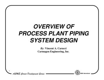
DX AMMONIA PIPING HANDBOOK – 3rd EDITION, REV AThis Piping Handbook is intended to guide the reader through the process of successfullydesigning and implementing DX Ammonia from 50F to -50F and realizing the benefits of:II.Dramatically reduced ammonia chargeSimplified controlsEnergy efficient dry suction lineReduced line sizesElimination of ammonia recirculator pumpsPatentsThe Colmac Advanced DX Ammonia system and evaporator technology described in thisPiping Handbook are covered by one or more of the following US 057III.System ConfigurationColmac Advanced DX Ammonia can be applied to any temperature level and systemconfiguration. P&ID diagrams for various typical systems are shown in Appendix A,simplified for purposes of clarity. Selection and system piping details (relief valves, purgers,isolation valves, vessel designs, etc) should follow industry guidelines as found in the IIARAmmonia Piping Handbook (IIAR 2004). The diagrams are not intended to present anexhaustive range of configurations – every industrial refrigeration system will have uniquefeatures and requirements. This information is presented to illustrate the general systemfeatures particular to a successful DX Ammonia design. Note that it is always good practiceto install an air purger on any industrial ammonia system. For the sake of simplicity airpurgers are not shown in these P&IDs. The reader is referred to the purger manufacturer forproper piping, installation, and operation of their equipment.1. Single Stage with Single or Multiple Temperature Levels - Figure A1This system is very simple with only a single compressor suction pressure level and asingle suction accumulator vessel. Evaporators can be operated at multipletemperatures by using back pressure regulating valves (BPRV) for the highertemperature level(s). Depending on how much of the load is at the higher temperaturelevel(s), this system can be very energy inefficient. A typical application for this P&IDwould be a fruit and/or vegetable storage facility. Expected charge for this type ofsystem is in the range of 6.5 to 7 lbs of ammonia per ton of refrigeration.Important features in Figure A1 required for proper DX ammonia operation include:ENG00019934 REV APage 4 of 59 2016 Colmac Coil Manufacturing Inc.
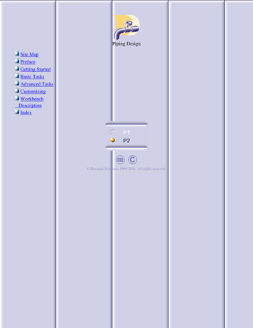
DX AMMONIA PIPING HANDBOOK – 3rd EDITION, REV Aa. Defrost condensate from hot gas defrosting units is returned to the suctionaccumulator. This effectively captures any water in the ammonia in this vesselwhere it can be distilled and removed from the system.b. Defrost condensate returning from hot gas defrosting units is utilized in theflooded plate heat exchanger to subcool the high pressure liquid. When there isinsufficient condensate to keep the subcooler flooded, makeup liquid is addedvia a makeup line to maintain a liquid level in the accumulator sufficient toachieve the required amount of subcooling. Conversely, the heat generated bysubcooling must equal or exceed the amount of heat needed to vaporize all ofthe defrost condensate returning from hot gas defrosting evaporators. This willbe the case provided the number of defrosts per day does not exceed (4) x 15minutes each (hot gas on time) assuming a room temperature of 32 deg F. If thefrost load is high enough to require more than (4) x defrosts per day, then thesubcooling load will not be high enough to vaporize all the defrost condensateand a liquid transfer system must be added to transfer the excess liquidrefrigerant from the suction accumulator back to the high pressure receiver.c. The water still shown in this system is heated by high pressure make-up liquid.The amount of make-up liquid called for will depend on the subcooling load andthe amount of defrost condensate returning to the accumulator as described in(b) above. Note that since the still is vented to the same accumulator the liquidis coming from, it must be positioned at an elevation lower than theaccumulator.d. The liquid line pressure is nominally reduced by a pressure reducing valve (PRV)downstream of the subcooler heat exchanger. The purpose of the PRV is tostabilize the liquid line pressure which improves the operation of expansionvalves (reduces the potential for hunting).e. Any oil leaving the oil separator as vapor will be condensed back to liquid in thecondenser and settle to the bottom of the high pressure receiver. The liquidsupply to the liquid line should be taken from a point 2-3" up from the bottomof the receiver vessel on the end opposite the connection coming from theoutlet of the condenser. This will result in a process of secondary oil separationin the pool of high pressure liquid in the receiver and will significantly reducethe amount of oil circulated to the evaporators.f. When liquid injection oil cooling is used as shown in this P&ID, liquid for oilcooling should be taken from a drop leg located between the inlet connection(coming from the condenser outlet) and outlet connection (to the liquid line).The drop leg gives priority liquid to the compressors for cooling and also returnsany accumulated oil.g. Hot gas for defrosting is taken from the top of the high pressure receiver tominimize the amount of oil sent to the evaporators in the hot gas. Forcing thehot gas to pass through the receiver vessel serves to desuperheat and "de-oil"the gas prior to entering the hot gas line.h. A pressure reducing valve (PRV) can be installed in the hot gas line to managethe pressure and flow of hot gas for defrosting adding to system stability.2. Single Stage Economized Screw w/ Multiple Temperatures (Te -20 deg F) - Figure A2ENG00019934 REV APage 5 of 59 2016 Colmac Coil Manufacturing Inc.
DX AMMONIA PIPING HANDBOOK – 3rd EDITION, REV AThis system configuration is widely used in cold storage warehouses due to its' costeffectiveness, simplicity, and flexibility. Recent developments with liquid injection oilcooling of screw compressors as shown in this P&ID have significantly reduced theenergy penalty traditionally associated with this oil cooling method. This P&ID isintended for systems which have the low side operating at positive pressures. If the lowside pressure is less than about 4 - 5 psig then an oil pot must be added to the lowtemperature accumulator to safely drain oil. Expected charge for this type of system isin the range of 6.5 to 7 lbs of ammonia per ton of refrigeration.Important features in Figure A2 required for proper DX ammonia operation include:a. Defrost condensate from hot gas defrosting units is returned to the highpressure suction accumulator. This effectively captures any water in theammonia in this vessel where it can be distilled and removed.b. Defrost condensate returning from hot gas defrosting units is utilized in theflooded plate heat exchanger to subcool the high pressure liquid. When there isinsufficient condensate to keep the subcooler flooded, makeup liquid is addedvia a makeup line to maintain a liquid level in the accumulator sufficient toachieve the required amount of subcooling. Conversely, the heat generated bysubcooling must equal or exceed the amount of heat needed to vaporize all ofthe defrost condensate returning from hot gas defrosting evaporators. This willbe the case provided the number of defrosts per day does not exceed (4) x 15minute (hot gas on time) defrosts in 32 deg F rooms and (2) x 15 minute (hot gason time) defrosts in -10 to -5 deg F rooms. If the frost load is high enough torequire more defrosts per day than this, then the subcooling load may not behigh enough to vaporize all the defrost condensate and a liquid transfer systemshould be added to transfer the excess liquid refrigerant from the suctionaccumulator back to the high pressure receiver (see Figure A3).c. An electric heater is shown in the drop leg of the low pressure suctionaccumulator to heat any oil that may have accumulated. If the low side pressureis less than about 4 - 5 psig then an oil pot must be added to the lowtemperature accumulator to safely drain oil.d. The water still shown in this system is heated by the high pressure liquid. Thevent line from the still is connected to the low pressure suction accumulator inorder to achieve the greatest distilling effect possible. It should only benecessary to operate the still during startup and commissioning in order toinitially dry out the system. After the first few weeks of operation (or after it isconfirmed that all of the water has been removed from the ammonia), the linefrom the high pressure accumulator to the still should be closed and the still leftidle. With systems which operate the low side in a vacuum (blast freezing), thestill should be operated once or twice per year to remove any water that mayhave accumulated in the ammonia.e. The liquid line pressure is nominally reduced by a pressure reducing valve (PRV)downstream of the subcooler heat exchanger. The purpose of the PRV is tostabilize the liquid line pressure which improves the operation of expansionvalves (reduces the potential for hunting).ENG00019934 REV APage 6 of 59 2016 Colmac Coil Manufacturing Inc.
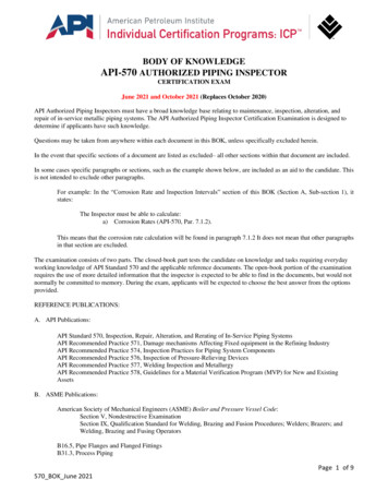
DX AMMONIA PIPING HANDBOOK – 3rd EDITION, REV Af.Any oil leaving the oil separator as vapor will be condensed back to liquid in thecondenser and settle to the bottom of the high pressure receiver. The liquidsupply to the liquid line should be taken from a point 2-3" up from the bottomof the receiver vessel on the end opposite the connection coming from theoutlet of the condenser. This will result in a process of secondary oil separationin the pool of high pressure liquid in the receiver and will significantly reducethe amount of oil circulated to the evaporators.g. When liquid injection oil cooling is used as shown in this P&ID, liquid for oilcooling should be taken from a drop leg located between the inlet connection(coming from the condenser outlet) and outlet connection (to the liquid line).The drop leg gives priority liquid to the compressors for cooling and also returnsany accumulated oil.h. Hot gas for defrosting is taken from the top of the high pressure receiver tominimize the amount of oil sent to the evaporators in the hot gas. Forcing thehot gas to pass through the receiver vessel serves to desuperheat and "de-oil"the gas prior to entering the hot gas line.i. A pressure reducing valve (PRV) can be installed in the hot gas line to managethe pressure and flow of hot gas for defrosting adding to system stability.3. Single Stage Economized Screw w/ Multiple Temperatures - Figure A3This system configuration is similar to Figure A2 in that it shows an economized screwcompressor system with multiple temperature levels typical of a freezer cold storagefacility. Here, however, a transfer line is added between the high and low temperaturesuction accumulators to allow excess liquid to move to the low temperatureaccumulator. A liquid transfer system is incorporated with the low temperatureaccumulator to move the excess liquid back to the high pressure receiver as needed.The liquid transfer system shown will be required when the number of defrosts exceedsapproximately (4) x defrosts per day in medium temperature (32 deg F) rooms and/or(2) x defrosts per day in freezer rooms. The system shown is also appropriate forfreezing where the low side pressure is below 0 psig with the necessary oil pot installedon the low temperature accumulator. Expected charge for this type of system is in therange of 6.5 to 7 lbs of ammonia per ton of refrigeration.Important features in Figure A3 required for proper DX ammonia operation include:a. Defrost condensate from hot gas defrosting units is returned to the highpressure suction accumulator. This effectively captures any water in theammonia in this vessel where it can be distilled and removed.b. Defrost condensate returning from hot gas defrosting units is utilized in theflooded plate heat exchanger to subcool the high pressure liquid. When there isinsufficient condensate to keep the subcooler flooded, makeup liquid is addedvia a makeup line to maintain a liquid level in the accumulator sufficient toachieve the required amount of subcooling. When the number of defrostsexceeds approximately (4) x defrosts per day in medium temperature (32 deg F)rooms and/or (2) x defrosts per day in freezer rooms, it is likely that excessdefrost condensate will have to be drained from the high temperatureENG00019934 REV APage 7 of 59 2016 Colmac Coil Manufacturing Inc.
DX AMMONIA PIPING HANDBOOK – 3rd EDITION, REV Ac.d.e.f.g.h.accumulator to the low temperature accumulator via the transfer line. Fromthere this excess liquid is transferred back to the high pressure receiver usingthe liquid transfer system shown.The water still shown in this system is heated by high pressure liquid. The ventline from the still is connected to the low pressure suction accumulator in orderto achieve the greatest distilling effect possible. It should only be necessary tooperate the still during startup and commissioning in order to initially dry outthe system. After the first few weeks of operation most of the water will havebeen removed from the system and the line from the high pressure accumulatorto the still should be closed and the still left idle. With systems which operatethe low side in a vacuum (blast freezing), the still should be operated once ortwice per year to remove any water that may have accumulated in theammonia.The liquid line pressure is nominally reduced by a pressure reducing valve (PRV)downstream of the subcooler heat exchanger. The purpose of the PRV is tostabilize the liquid line pressure which improves the operation of expansionvalves (reduces the potential for hunting).Any oil leaving the oil separator as vapor will be condensed back to liquid in thecondenser and settle to the bottom of the high pressure receiver. The liquidsupply to the liquid line should be taken from a point 2-3" up from the bottomof the receiver vessel on the end opposite the connection coming from theoutlet of the condenser. This will result in a process of secondary oil separationin the pool of high pressure liquid in the receiver and will significantly reducethe amount of oil circulated to the evaporators.When liquid injection oil cooling is used as shown in this P&ID, liquid for oilcooling should be taken from a drop leg located between the inlet connection(coming from the condenser outlet) and outlet connection (to the liquid line).The drop leg gives priority liquid to the compressors for cooling and also returnsany accumulated oil.Hot gas for defrosting is taken from the top of the high pressure receiver tominimize the amount of oil sent to the evaporators in the hot gas. Forcing thehot gas to pass through the receiver vessel serves to desuperheat and "de-oil"the gas prior to entering the hot gas line.A pressure reducing valve (PRV) can be installed in the hot gas line to managethe pressure and flow of hot gas for defrosting adding to system stability.4. Single Stage (Screw) Glycol Med Temperature/DX Low Temperature - Figure A4Figure A4 shows a very low ammonia charge design which utilizes a secondaryrefrigerant (glycol) for the high temperature rooms. The system uses a plate type watercooled condenser to further reduce the ammonia charge. This in combination with lowcharge DX evaporators in the low temperature rooms produces a system with anammonia charge in the range of only 3 lbs of ammonia per ton of refrigeration.Important features in Figure A4 required for proper DX ammonia operation include:ENG00019934 REV APage 8 of 59 2016 Colmac Coil Manufacturing Inc.
DX AMMONIA PIPING HANDBOOK – 3rd EDITION, REV Aa. Defrost condensate from hot gas defrosting units is returned to the hightemperature accumulator which also acts as the glycol chiller surge drum. Thiseffectively captures any water in the ammonia in this vessel where it can bedistilled and removed.b. The plate type condenser sends makeup liquid to the glycol chiller surge drumvia a high side float valve. This vessel handles the surge volume of liquid for thesystem. Priority high pressure liquid for the low temperature evaporators is sentfirst to a boil-out coil in the low temperature accumulator and then then to aplate type DX subcooler.c. The liquid line pressure is nominally reduced by a pressure reducing valve (PRV)downstream of the subcooler heat exchanger. The purpose of the PRV is tostabilize the liquid line pressure which improves the operation of expansionvalves (reduces the potential for hunting).d. A heated oil pot is shown in the drop leg of the low temperature suctionaccumulator.e. Oil is cooled using cooling tower water.f. A pressure reducing valve (PRV) can be installed in the hot gas line to managethe pressure and flow of hot gas for defrosting adding to system stability.5. Two Stage Screw with Intercooling - Figure A5Two stage compression as shown in Figure A5 offers the highest energy efficiency of anyof the refrigeration system configurations shown. This will be the design of choice wheneither very low operating costs and/or when blast freezing temperatures are required.The glycol oil cooling method shown in this P&ID minimizes the system ammonia chargeand also offers the possibility of heat reclaim, underfloor heating, etc. Expected chargefor this type of system is in the range of 6.5 to 7 lbs of ammonia per ton of refrigeration.Important features in Figure A5 required for proper DX ammonia operation include:a. Defrost condensate from hot gas defrosting units is returned to the highpressure suction accumulator/intercooler. This effectively captures any water inthe ammonia in this vessel where it can be distilled and removed.b. Defrost condensate returning from hot gas defrosting units is utilized in theflooded plate heat exchanger piped to the high temperature suctionaccumulator to subcool the high pressure liquid. The condensate also quenchesthe booster discharge gas. When there is insufficient condensate to keep thesubcooler flooded and quench the booster discharge gas, makeup liquid isadded via a makeup line controlled on liquid level in the accumulator.c. The water still shown in this system is heated by the high pressure liquid feedingthe makeup liquid line. The vent line from the still is connected to the lowpressure suction accumulator in order to achieve the greatest distilling effectpossible. It should only be necessary to operate the still during startup andcommissioning in order to initially dry out the system. After the first few weeksof operation (or after it is confirmed that all of the water has been removedfrom the ammonia), the line from the high pressure accumulator to the stillshould be closed and the still left idle. With systems which operate the low sideENG00019934 REV APage 9 of 59 2016 Colmac Coil Manufacturing Inc.
DX AMMONIA PIPING HANDBOOK – 3rd EDITION, REV Ain a vacuum (blast freezing), the still should be operated once or twice per yearto remove any water that may have accumulated in the ammonia.d. The liquid line pressure is nominally reduced by a pressure reducing valve (PRV)downstream of the subcooler heat exchanger. The purpose of the PRV is tostabilize the liquid line pressure which improves the operation of expansionvalves (reduces the potential for hunting).e. Any oil leaving the oil separator as vapor will be condensed back to liquid in thecondenser and settle to the bottom of the high pressure receiver. The liquidsupply to the liquid line should be taken from a point 2-3" up from the bottomof the receiver vessel on the end opposite the connection coming from theoutlet of the condenser. This will result in a process of secondary oil separationin the pool of high pressure liquid in the receiver and will significantly reducethe amount of oil circulated to the evaporators. Any accumulated oil in the dropleg can be periodically drained or automatically returned to the compressors(piping not shown).f. Hot gas for defrosting is taken from the top of the high pressure receiver tominimize the amount of oil sent to the evaporators in the hot gas. Forcing thehot gas to pass through the receiver vessel serves to desuperheat and "de-oil"the gas prior to entering the hot gas line.g. A pressure reducing valve (PRV) can be installed in the hot gas line to managethe pressure and flow of hot gas for defrosting adding to system stability.IV.System StabilityWith liquid overfeed and gravity flooded systems, liquid return to the recirculator vessel orthe surge drum is normal and expected through the wet suction line. The recirculator vesselor surge drum effectively separates returning liquid from vapor and ensures that the drysuction line carries only vapor back to the compressor.DX systems, on the other hand, are designed to operate with a dry suction line and are bydefinition more sensitive to liquid floodback. Industrial DX systems should incorporate asuction accumulator vessel to prevent liquid slugging of the compressor during a floodbackevent, however, excessive floodback from evaporators can cause high level alarming andsystem shutdown until the excess liquid in the suction accumulator can be transferred backto the high pressure side of the system. Stable and smooth operation of the system and theevaporator expansion valve(s) is critical to avoiding liquid floodback. Instabilities and/orrapid changes in discharge and suction pressures during operation are the typical cause ofunstable operation of expansion valves and should be considered carefully by the systemdesigner and operator(s).Rapid changes in system discharge pressure can cause system instabilities in a number ofways. A sudden reduction in discharge pressure can result in undesirable flashing of liquidrefrigerant in liquid lines and will also be accompanied by a sympathetic, albeit smaller,reduction in suction pressure. A sudden increase in discharge pressure will be accompaniedby a sympathetic, albeit smaller, increase in suction pressure. An increase in suctionENG00019934 REV APage 10 of 59 2016 Colmac Coil Manufacturing Inc.
DX AMMONIA PIPING HANDBOOK – 3rd EDITION, REV Apressure, if large enough and rapid e
Ammonia Piping Handbook (IIAR 2004). The diagrams are not intended to present an exhaustive range of configurations – every industrial refrigeration system will have unique features and requirements. This information is presented to illustrate the general system features parti