Transcription
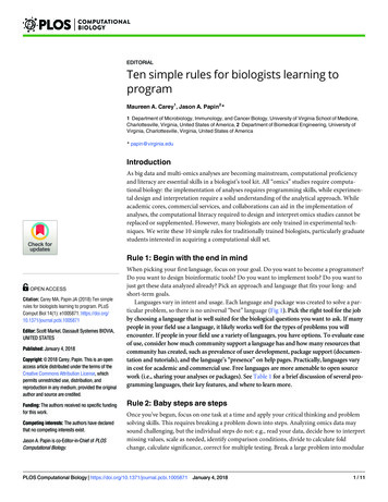
sTraining manualSinumerik 808D Programming and OperatingProcedures for TurningVersion 2013-01
sNotesProgramming and Operating — TurningPage 2808D
Basic knowledge of programming for turning is required,before operating of a machine !sContentsPreparationSwitch On andReferencingPages 5 7Pages 9 10Tool SetupPages 13 22WorkpieceSetupPages 25 28Create PartProgramPart 1MachinePiecesProgramRestartPages 67 69TestProgramSimulateProgramPages 63 64Pages 59 60Pages 71 72Pages 31 38Create PartProgramPart 2Pages 41 56AdditionalInformationPart 1Pages 75 80AdditionalInformationPart 2SampleProgramISO ModeAppendixPages 93 98Pages 101 111Pages 113 116EndPages 83 90808DPage 3Programming and Operating — Turning
sNotesAbsolute value and incremental value34Manual tool change16Editing part program33MDA83Executing function M21Moving axis with handwheel17Calculator89Part programming31Time change79Protection levelsContour editor41Program execution63Creating and measuring tools13Breakpoint search71Creating zero offsets26Reference point10Cycles41RS232c and USB75Dry run64Saving data79Jogging spindle21Simulation59Help77Subprograms84Sample programs9367List of programming functions113Tool wear69Timers/countersManual start spindle25ISO modeProgramming and Operating — TurningPage 47101808D
sPreparationUnit DescriptionPPUFunction ofkeyboardThis unit describes the 808D PPU and MCP functionality, the coordinatesystem of a turning machine and how to enter passwords to access thesystem.The 808D panel processing unit (PPU) isused to input data tothe CNC and to navigate to operatingareas of the system.Unit ContentPPUFunction ofkeyboardUserinterfaceMCP sswordsMCPOEMkeys808DMenu navigationOperating areanavigationMCP modeChangingThe 808D machinecontrol panel (MCP) isused to select themachine operatingmode :JOG - MDA - AUTOEndPage 5Mode NavigationProgramming and Operating — Turning
sPreparationUserinterfaceMCPMoving axisAxis movementThe 808D machine controlpanel (MCP) is used tocontrol manual operation ofthe axis.The machine can be movedwith the appropriate keys.808D(PPU)haseight vertical softkeys(abbr. SKs) on theright of the screen.These SKs can beactivated with thecorresponding button(located on the right).MCPOEMkeysOEM keyThe 808D machine controlpanel (MCP) is used to control OEM machine functions.The machine functions canbe activated with the appropriate keys.Programming and Operating — Turning808D(PPU)has eight horizontal SKs on the bottom of thescreen. These SKs can be activated with the corresponding button(located below).Page 6808D
dsThe Sinumerik 808D usesa coordinate system whichis derived from the DIN66217 standard.The system is an international standard and ensures compatibility between machines and coordinate programming.The primary function of thecoordinate system is toensure that the tool lengthand tool radius are calculated correctly in the respective axis.The machine zero point (M) is determined by the machinemanufacturer and cannot be changed.Passwords at the control are used to set the user’sright to access the system. Tasks such as ”Basic Operating”, “Advanced Operating” and commissioningfunctions all depend on the passwords.No passwordCustomer’s passwordManufacturer’s passwordChangingpasswordStep 1Machine operatorAdvanced operatorOEM engineerCustomer’s password CUSTOMERManufacturer’s password SUNRISEUsually the machine operator does not needto change the password.The service mode is openedwith the appropriate keycombination.In the service mode, thepassword can be activatedand deactivated. Step 2The workpiece zero point (W) is the origin of the workpiececoordinate system.Enter customer passwordThe reference point (R) is used for synchronizing the measuring system.Change customer passwordDelete customer passwordThe tool holder reference point (F) is used to determine the tooloffset.End808DPage 7Programming and Operating — Turning
sNotesProgramming and Operating — TurningPage 8808D
sSwitch OnAndReferencingContentUnit DescriptionSwitch onthemachineThis unit describes how to switch the machine on and reference it.Please note the explicit switching on rules as specifiedby the machine manufacturer.Unit ContentStep 1Turn on the main switch of the machine.Switch onthemachineThe main switch is usually at the rear of the machine.ReferencethemachineStep 2EndMake sure you perform the following operation!Release all the EMERGENCY STOPbuttons on the machine!End808DPage 9Programming and Operating — Turning
sSwitch OnAndReferencingSEQUENCEReferencethemachineAfter power on, the machine must firstbe referenced!After completing the referencingprocedure for all axes, the referenced symbol is displayed next tothe axis identifier.Step 1After power on, the machine will bein the reference point approachmode (default).Step 3After returning to JOG mode, usethe axis traversing keys to move themachine manually.If the axis is not referenced, the nonreferenced symbol (circle) is displayed between the axis identifierand the value.Step 2Now the machine can be operated inJOG mode.During normal operation (JOG), thereference symbol is not shown on thescreen.The axes are referenced with thecorresponding axis traversing keys.The traversing direction keys arespecified by the machine manufacturer.EndProgramming and Operating — TurningPage 10808D
sNotes808DPage 11Programming and Operating — Turning
sNotesProgramming and Operating — TurningPage 12808D
sTool SetupContentUnit DescriptionCreate toolThis unit describes how to create and set up tools.Step 1A tool must have been created andmeasured before executing the program.Please make sure the system is in JOG mode.Press “Offset” on the PPU.Unit ContentPress the “Tool list” SK on the PPU.Create toolMovemachinewith handwheelTool edgepositioncodeStartspindleCreate tooledgeMeasuretoolLoad toolinto activepositionJOGspindle808DExecute MfunctionTest tooloffsetresultsEndPage 13Programming and Operating — Turning
sTool SetupSEQUENCEStep 2The range of tool numbers which can be createdby this system is 1 32000.The machine can be loaded with a maximum of64 tools / 128 tool edges.Tool edgepositioncodePrinciple of correct tool edge positioncode selection: Select the corresponding tool edge position code accordingto actual tool point direction!Press the “New tool” SK on the PPU.Observe the relationship between the tool point direction and the positivedirection of the X axis and the Z axis.Select the type of required tool.Find the corresponding position relationship in the figure below and enterthe number in “Edge position”; the red coordinate in the purple circle is theselected position code.As to “turning tool” and “grooving tool”, 808D provide 4edges (#1 4) which are shown on the left figure.Enter “1” at “Tool No.”Enter “3” at “Edgeposition”.As to “drilling tool” and “tapping tool ”, 808D provideonly 1 edge (#7) which is also shown on the left figure.The correct “Edgeposition” selectiondirectly determinesthe correct toolcompensation which willbe described in thenext unit.Press the “OK” SK on the PPUNote: Not every tool has eight position codes. All the options are shown above.Note that the tool tip direction here is the direction afterthe correct tool offset, not only the direction in tool loading. And the correctness of tool edge position code directly affects the correctness of the tool tip radius compensation!The tool edge position code can also be changed in the position showed in the figure.Enter the “Radius” or “Tipwidth” as required.Press the “Input” button on the PPUProgramming and Operating — TurningPage 14808D
sTool SetupSEQUENCEExampleCommon tool edge position code choices are as follows:Createtool edgeA tool must have been created andselected before creating a tool edge.Step 1 Use “D” code to represent the tool edge. The system activates theNo.1 tool edge as default at the beginning.Press the “Offset” key on the PPU.Press the “Tool list” SK on the PPU. Use direction keys to select the tool whichneeds to add a tool edge.or Press the “Edges” SK on the PPU.Press the “New edge” SK on the PPU.808DPage 15Programming and Operating — Turning
sTool SetupSEQUENCEStep 2Load toolinto activepositionA new tool edge can be added in this way and different lengths and radiican be entered as required.The red circle shows the actual active tool and tool edge, the purplecircle shows how many tool edges have been created and the relateddata for each tool edge.A tool must have been created in thesystem before it can be loaded intothe active position.Press the “Machine” key on the PPU.Press the “JOG” key on the MCP.Press the “T.S.M” SK on the PPU.Enter tool number “1” in “T”.Press “CYCLE START” on the MCP.A maximum of nine tool edges can be created for eachtool!Different tool lengths and radii can be saved in differenttool edges as required.Please select the right tool edge for machining accordingto requirement!Programming and Operating — TurningPress the “Back” SK on the PPU.Page 16808D
sTool SetupSEQUENCEMovemachinewith handwheelSelect the required override incrementaccording to the buttons on the right(this selection fits all axes)Make sure there is no obstructionwhen moving the tool to avoid a crash.The override increment is “0.001 mm”A handwheel can control the axis motion instead of the “JOG” button.The override increment is “0.010 mm”Press the “Machine” key on the PPU.The override increment is “0.100 mm”Press the “Handwheel” key on the MCP.The selected axis can now be moved with the handwheel.Press “JOG” on the MCP to endthe “Handwheel” function.Select the axis you want to move withthe appropriate keys on the MCPNotes:if set MD14512[16] 80 , the system will deactivate the function of MCP for selecting the axis of handwheel, the user will have toactivate “Handwheel” function with PPU softkeyUnder “WCS” or “MCS”,a handwheel will be shownbeside the axis symbols,representing that the axiscan be moved using handwheel.808DSelect therequired axison the right ofthe PPU; theselected axisis shown witha Page 17Programming and Operating — Turning
sTool SetupSEQUENCEStartspindleA tool must have been loaded androtated to the position.Start the spindle before adjusting tools as follows:Press the “Machine” key on the PPU.Press the “JOG” key on the MCP.Press the “T.S.M” SK on the PPU.Press “Reset” on the MCP to stop the spindle rotation.Enter “500” at “Spindle speed”.Press the “Back” SK on the PPU.Select “M3” using the “Select” keyon the PPU.A tool must have been created andloaded before it can be measured!MeasuretoolStep 1Measure length:XPress the “Machine” key on the PPU.Press the “CYCLE START” key onthe MCP.Press the “JOG” key on the MCP.Press the “Meas. tool” SK on the PPU.Press the “Measure X” SK on the PPU.Programming and Operating — TurningPage 18808D
sTool SetupSEQUENCEEnter 50 in “ø”(this is the diameter of the workpiece)Use the traversing keys on theMCP to move the axis to the adjusted position.Note: “X 0” or “Z 0” in the workpiececoordinate system is shown as “X0” /“Z0” in the following text.Press the “Set length X” SK on thePPU.Use the“Handwheel”key on theMCP andselect a suitable feedrateoverride tomove the toolto X0.808DMove directly to zero point.Page 19Programming and Operating — Turning
sTool SetupSEQUENCEStep 2Enter “0” in “Z0”(this is the distance between the toolpoint and the zero point)Set length:ZPress the “Set length Z” SK on thePPU.Use the traversing keys on theMCP to move the axis to the adjusted position.Press the “Set length Z” SK on the PPU.Press the “Back” SK on the PPU.Use the“Handwheel”key on theMCP andselect a suitable feedrateoverride tomove the toolto Z0.Programming and Operating — TurningMove directly to zero pointPage 20808D
sTool SetupSEQUENCEJOGspindleExecute MfunctionA tool must have been loaded androtated to the position!Please make sure all the machineaxes are in safe positions beforeexecuting the M function!Press the “Machine” key on the PPU.Press the “Machine” key on the PPU.Press the “JOG” key on the MCP.Press the “T.S.M” SK on the PPU.Use the direction key to move thehighlighted cursor to “Other Mfunction” and enter “8”. This willstart the coolant.Press the spindle direction key on the MCPto start/stop the spindle.Press “Spindle left” on the MCP to start thespindle in the counter-clockwise direction.Press “Spindle stop” on the MCP to stopthe spindle.Press “Spindle right” on the MCP to startthe spindle in the clockwise direction.Press “CYCLE START” on the MCP.You can see that the coolant functionkey on the MCP is active.Press the “Reset” key on the MCP tostop the coolant function.Press the “Back” SK on the PPU.808DPage 21Programming and Operating — Turning
sTool SetupSEQUENCETest tooloffsetresultsThe tool setup and workpiece setupmust have been performed correctly sothat it can be tested as follows!In order to ensure the machine safety and correctness, the results of thetool offset should be tested appropriately.Press the “Machine” key on the PPU.Press the “MDA” key on the MCP.Press the “Delete file” SK on the PPU.Enter the test program recommendedon the right (can also be customized).G500; select offsetpanel as requiredT1 D1G00 X0 Z5Press the “ROV” key to ensure the“ROV” function is active (lit up).Note: The ROV function activates the feedrate override switch underthe G00 function.Make sure the feedrate override on the MCP is at 0%!Press “CYCLE START” on the MCP.Increase the feedrate override gradually to avoid accidents caused by anaxis moving too fast and observe whether the axis moves to the set position.Programming and Operating — TurningPage 22808D
sNotes808DPage 23Programming and Operating — Turning
sNotesProgramming and Operating — TurningPage 24808D
sWorkpieceSetupContentSEQUENCEUnit DescriptionManualstartspindleThis unit describes how to set the workpiece offset and test the tool results.A tool must be loaded and rotated tothe position.Before measuring, the spindle can be started as follows:Press the “Machine” key on the PPU.Unit ContentPress the “JOG” key on the MCP.Press the “T.S.M” SK on the PPU.ManualstartspindleCreateworkpieceoffsetEnter “500” in “Spindle speed” on the PPU.Select “M3” as the “Spindle direction”using the “Select” key on the PPU.Test tooloffsetresultsEndPress “CYCLE START” on the MCP.808DPage 25Programming and Operating — Turning
sWorkpieceSetupSEQUENCECreateworkpieceoffsetA tool must have be created andmeasured before it can be used to setthe workpiece offset.Make sure the active tool is the measured tool!Press the “Machine” key on the PPU.Press the “JOG” key on the MCP.Press the “Reset” key on the MCPto stop the spindle rotation.Press the “Offset” key on the PPU.Press the “Back” SK on the PPU.Press the “Work offset” SK on the PPU.Press the “Meas.work.” SK on the PPU.Programming and Operating — TurningPage 26808D
sWorkpieceSetupSEQUENCEStep 2Using a tool that has a measured “Tool length”, move the tool to a knownposition on the workpiece. Using either JOG or Handwheel, scratch anedge and then calculate the zero point of the workpiece.The process of setting the zero point (“Z0”) is described below.Press the “Handwheel” key on the MCP tomove the tool to the Z0 position on theworkpiece.Press the SK on the PPU to selectthe required setting axis.Press the axis traverse keys tomove the tool to the required setting position in the Z axis.Enter tool number “1” in “T”.Set “Save in” as “G54” (or other offset).Set “Distance” as “0”Press the “Set work offset” SK on the PPU.Repeat the operations to set the “X” zero point.Press the “Back” SK on the PPU aftermeasuring.808DPage 27Programming and Operating — Turning
sWorkpieceSetupSEQUENCETest tooloffsetresultsThe tool setup and workpiece setupmust have been performed correctly sothat it can be tested as follows!In order to ensure the machine safety and correctness, the results of thetool offset should be tested appropriately.Press the “MDA” key on the MCP.Press the “Delete file” SK on the PPU.Enter the test program recommended on the right.Press the “ROV” key to ensure the “ROV”function is active (the function is activatedwhen the light on the key is on).G54 (select offset panel asrequired)T1 D1G00 X0 Z5Note: The ROV function activates the feedrate override switch underthe G00 function.Make sure the feedrate override on the MCP is at 0%!Press “CYCLE START” on the MCP.Increase the feedrate override gradually to avoid accidents caused by anaxis moving too fast and observe whether the axis moves to the set position.Programming and Operating — TurningPage 28808D
sNotes808DPage 29Programming and Operating — Turning
sNotesProgramming and Operating — TurningPage 30808D
sCreate PartProgramPart 1ContentBASIC THEORYUnit DescriptionProgramstructureThis unit describes how to create and edit a part program, and get toknow the most important CNC commands required to produce a workpiece.A standard program structure is not needed but isrecommended in order to provide clarity for the machine operator. Siemens recommends the followingstructure:Return to change toolT,F,S functionUnit ContentGeometry data / motionReturn to change toolProgramstructureDefinition oftargetpositionTurningcircles andarcsCreateprogramRapidmotionMoving to afixedpositionGeometry data / motionControllingthe spindleT,F,S functionEditprogramTools andmotionT,F,S functionReturn to change toolGeometry data / motionImperialand MetricsystemBehavior atcornersSetting adelay in theprogramReturn to change toolEnd/stop positionN5 G17 G90 G54 G71N10 T1 D1N15 S5000 M3 G95 F0.3N20 G00 X100 Z2N25 G01 Z-5N30 X105N35 G00 SUPA X300 Z50 D0N40 T2 D1N45 S3000 M3 G95 F0.2N50 G00 X99 Z2N55 G01 Z-5N60 X105N65 G00 SUPA X300 Z50 D0N70 T3 D1N75 S3000 M3 G95 F0.2N80 G00 X105 Z-25N85 G01 X90N90 X105N95 G00 SUPA X300 Z50 D0M30End808DPage 31Programming and Operating — Turning
sCreate PartProgramPart 1BASIC THEORY1Step 4CreateprogramThe following sequence should be followed to createa part program:Step 1Programs can becreated with the“program manager”.You can select the“program manager”using the key located on the PPU.Step 2Select NC as the storage location for theprogram. Programs can only be createdin the NC.Step 3Create a newprogram withthe “New” SKon the right ofthe PPU.You canchoose“New” or“New directory”.Choose“New” tocreate aprogram.Choose“New directory” tocreate afile.2Step 5Now theprogram isopen andcan beedited.After editing the system will save it automatically.EndProgramming and Operating — TurningPage 32808D
sCreate PartProgramPart 1BASIC THEORYEditprogramInchesand mmG71With G71 at theheader, the geometry data willbe in the metricunit sys-tem,feedrates in thedefault metricsystem.The program shown in the editor can becreated and edited with the correct keys.G70With G70 at theheader, the geometry data willbe in the imperial(inches) unitsystem, thefeedrate in thedefault metricsystem.。808DPage 33Return to change toolN5 G17 G90 G54 G71Return to change toolN10 T1 D1N15 S5000 M3 G95 F0.3N20 G00 X100 Z1N25 G01 X-0.5N30 Z2N35 G00 X200 Z50Return to change toolN5 G17 G90 G54 G70T,F,S functionGeometry data / motionT,F,S functionGeometry data / motionReturn to change toolN10 T1 D1N15 S5000 M3 G95 F0.2N20 G00 X10 Z0.2N25 G01 X-0.2N30 Z0.2N35 G00 X10 Z10Programming and Operating — Turning
sCreate PartProgramPart 1BASIC THEORYDefinition oftargetpositionG500All absolute pathdata will be relative to this position. The positionis written in theG500 (basic) zerooffset.N5 G17 G90 G500 G71X0 Z50G500 ZG500 XN10 T1 D1N15 S5000 M3 G95 F0.3N20 G00 X50 Z5N25 G01 Z-5N30 Z5N35 G00 Z50 X100G90Absolute positioning;with G90 at the beginning of the program, thegeometry data whichfollows will be interpreted relative to the activezero point in the program, usually with G54or G500 or G500 G54.N5 G17 G90 G54 G71G91Relative positioning;with G91 you can addan incremental value(G91 defined data is therelative positioningusing the present position as the start point).Finally you shouldchange the program toabsolute positioning withG90.N5 G17 G90 G54 G70N10 T1 D1N15 S5000 M3 G95 F0.3N20 G00 X100 Z5N25 G01 Z-5N30 Z5N35 G00 Z500 X100OrG54 G55 G56 G57G58 G59With G500 0, theoffset for the workpiece can bestored in the G54workpiece offset.N5 G17 G90 G54 G71X0 Z50G54 ZG54 XOrG500 G54With G500 0and is activated,the value inG500 will beadded to thevalue in G54.G54 X0G54 Z0G500 ZProgramming and Operating — TurningG500 XN10 T1 D1N15 S5000 M3 G95 F0.3N20 G00 X0 Z5N25 G01 Z-5N30 Z5N35 G00 Z50 X100N5 G17 G90 G500 G71N10 T1 D1N15 S5000 M3 G95 F0.3N20 G00 G54 X20 Z5N25 G01 Z-5N30 Z5N35 G00 G53 Z50 X100Page 34N10 T1 D1N15 S5000 M3 G95 F0.3N20 G00 X3.93 Z0.196N25 G01 G91 Z-0.787N30 Z0.196N35 G00 G90 Z19.68 X10808D
sCreate PartProgramPart 1BASIC THEORYRapidmotionG00When G00 isactive in the program, the axis willtraverse at themaximum axisspeed in astraight line.N5 G17 G90 G54 G71Straight line (parallel/unparallel to axis)N10 T1 D1N15 S5000 M3 G95 F0.3N20 G00 X50 Z5N25 G01 Z-5N30 Z5N35 G00 Z500 X200Tools andmotionT1 D1With the “T” command the newtool can be selected, the ”D” command is used toactivate the toollength offset.M06 is also available for machineswith automatictool changer.808DN5 G17 G90 G54 G71N10 T1 D1N15 S5000 M3 G95 F0.3N20 G00 X50 Z5N25 G01 Z-5N30 Z5N35 G00 Z500 Z200 FeedrateSpindle speedFeed typeSpindle directionThe feedrate is defined in theprogram with “F”. Two types offeedrate are available:1. Feed per minute G942. Feed per revolution of thespindle G95G94Defines the feedrate in terms oftime mm/min.G95Defines the feedrate in terms ofspindle revolutions mm/rev.SThe spindle speed is definedwith ”S” S5000M3/M4The spindle direction is definedwith M3 and M4, clockwise/counter-clockwise respectively.G01When G01 is active in the program, the axis will traverse atthe programmed feedrate in astraight line, according to thefeedrate type defined by G94 orG95.,Page 35N5 G17 G90 G54 G71N10 T1 D1N15 S5000 M3 G95 F0.3N20 G00 X50 Z5N25 G01 Z-5N30 Z5N35 G00 Z500 Z200N5 G17 G90 G54 G71N10 T1 D1N15 S5000 M3 G95 F0.3N20 G00 X50 Z5N25 G01 Z-5N30 Z5N35 G00 Z500 Z200Straight line (parallel/unparallel to axis)Programming and Operating — Turning
sCreate PartProgramPart 1BASIC THEORYBehavior atcornersActivation/deactivation of thetool radius compensation when working onthe part contour.G41 / G42 and G40With G41/G42,the radius compensation of the tool will bedone in the directionof travel.G41:Compensationto left.G42:Compensationto right.G40:Compensationof the radius can bedeactivated.G41 directionalong the tool motion, the tool isalways on the left ofthe contour.Programming and Operating — TurningG42 directionalong the tool motion, the tool isalways on the rightof the contour.Arrow indicates thedirection of tool motionalong the contourPage 36808D
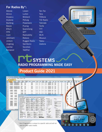
sCreate PartProgramPart 1BASIC THEORYTurningcircles andarcsThe circle radiusshown in the example on the right canbe produced with thespecified part program code.When milling circlesand arcs, you mustdefine the circlecenter point and thedistance betweenthe start point / endpoint and the centerpoint on the relativecoordinate.When working in theXZ coordinate system, the interpolationparameters I and Kare available.IDetermine tool radius of T1 D1XTool motion directionN5 G17 G90 G500 G71KX75, Z-35N10 T1 D1N15 S5000 M3 G95 F0.3N20 G00 X0 Z2N25 G01 Z0N30 G42 X50N45 G03 X75 Z-35 I-12 K-35N50 G01 Z-130N60 G40 X120 Z-140N35 G00 X300 Z500ZEPZ-130X50, Z0(I) -12(K)-35SPCPX0, Z0Z-130, X0SP start point of circleCP center point of circleNote:N45 can also be written as followsN45 G03 X75 Z-35 CR 37EP end point of circleI defined relative increment from start point to center point in XTwo common types of defining circlesand arcs:K defined relative increment from start point to center point in ZG2 define circle direction in traversing direction G2 clockwise①:G02/G03 X Z I k ;②:G02/G03 X Z CR ;Arcs 180º,CR is a positive numberArcs 180º,CR is a negative number808DG3 define circle direction in traversing direction G3 counter-clockwisePage 37Programming and Operating — Turning
sCreate PartProgramPart 1BASIC THEORYMoving to afixedpositionUsing the code G74,the machine canmove to the reference point automatically.Controllingthe spindleN5 G17 G90 G500 G71N10 T1 D1N15 S5000 M3 G95 F0.3N20 G00 X50 Z5N25 G01 Z-5N30 Z5N35 G74 X 0 ;reference pointThe following functions can beused to influence the operation ofthe spindle:M3 accelerate to programmedspeed clockwise.M4 accelerate to programmedspeed counter-clockwise.N5 G17 G90 G500 G71N10 T1 D1N15 S5000 M3 G95 F0.3N20 G00 X50 Z5N25 G01 Z-5N30 M5N35 Z5 M4N40 M5N45 M19N50 G00 X200 Z50M5 spindle decelerate to stop.Using the code G75,the machine canmove to the fixedposition defined bymachine supplierautomatically.N5 G17 G90 G500 G71N10 T1 D1N15 S5000 M3 G95 F0.3N20 G00 X50 Z5N25 G01 Z-5N30 Z5N35 G74 Z 0 ;reference pointN40 G75 X 0 ;fixed pointM19 orient the spindle to a specific angular position.Setting adelay in theprogramN5 G17 G90 G500 G71G04 can be used to pause thetools’ movements during operationG04 F5: Program dwells for 5 sThis makes the surface of theworkpiece much smoother.Programming and Operating — TurningPage 38N10 T1 D1N15 S5000 M3 G95 F0.3N20 G00 X50 Z5N25 G01 Z-5N30 G04 F5N35 Z5 M4N40 M5N45 M19N35 G00 X200 Z50808D
sNotes808DPage 39Programming and Operating — Turning
sNotesProgramming and Operating — TurningPage 40808D
sCreate PartProgramPart 2ContentBASIC THEORYUnit DescriptionContourturningcycleThis unit describes how to create and edit a part program, and get toknow the most important CNC commands required to produce a workpiece.Part 2Step 1The easiest way toperform roughing/finishing along thecontour is to usethe “contour turning” cycle function.By selecting the“Turn.” SK, you canenter the cycle andset parameters.Unit pingThreadcuttingCutting offDrillingcenterholes808DThe “Contour turning” SK can befound on the rightvertical menu.The related parameters canbe set on thescreen.EndPage 41Programming and Operating — Turning
sCreate PartProgramPart 2BASIC THEORYBy selecting the “Attach contour” SK, the contour milling data canbe inserted in the main program file behind the M30 command.You can edit and change it when selected. The sequence is asfollows:Open the cycle datasetting window andenter the name ofthe contour subprogram.After opening the contour data setting window, please make the followingsettings:Press “Attach contour ” on the PPU tocreate contour information at the program end. The cursor moves to thecontour editing posi-Make surethe cursor is in theediting position(shown in the figure on the left).Press “Cont.” on thePPU to open thecontour data settingwindow.Programming and Operating — TurningPage 42Enter appropriatestart point coordinates based on themachining figureand select the appropriate approach.Press the “Acceptelement” SK onthe PPU.Use the items onthe PPU to selectthe direction and thecontour shape andenter the corresponding coordinateparameters.808D
sCreate PartProgramPart 2BASIC THEORYThe selected direction is shown at thetop left side of PPU.After completing the steps, the system will return to the Edit interface. Press “Technicalinterface” on the PPU to return to the interfacefor setting the cycle data.The meaning of thehighlighted positionsis shown at thebottom of the PPUscreen.After finishing the parameter settings of CYCLE95, press the ”OK” SK on the PPU to insertthe corresponding cycles in the main program.With the “New” SK and “Contour milling”, the operation can beedited and saved in a subprogram.The editing in the subprogram is the same as above.Press the “Acceptelement” SK onthe PPU.Select differentitems to set thecontour until youhave finished editing the whole shapeof the contour.Press the “Acceptelement” SK on thePPU to enter theinformation in themain program(stored in the cursorposition after theM30 command).808DAfter all the settings take effect, the selected cycle and set data will betransferred to corresponding part program automatically (for further information, see next page).Step 2 Radius and chamfersThe radii and the chamfercan be produced usingthe contour editor, inconjunction with theroughing or finishing cycles.RND and CHR/CHF canbe found in the additivedescription of the T contour.Page 43RND RadiiCHR Chamfer(specified side length of isosceles triangle with chamfer as base line)CHF Chamfer(specified base line length of isoscelestriangle with chamfer as base line)Programming and Operating — Turning
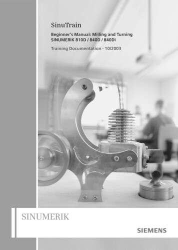
sCreate PartProgramPart 2BASIC THEORYN170 CYCLE95( "DEMO:DEMO E", 2.5, 0.2 , 0.1 , 0.15 , 0.35 , 0.2 , 0.15 , 9 , , ,);*************CONTOUR************DEMO:;#7 DlgK contour definition begin - Don't change!;*GP*;*RO*;*HD*G18 G90 DIAMON;*GP*G0 Z0 X16 ;*GP*G1 Z-2 X20 ;*GP*Z-15 ;*GP*Z-16.493 X19.2 RND 2.5 ;*GP*Z-20 RND 2.5 ;*GP*X30 CHR 1 ;*GP*Z-35 ;*GP*X40 CHR 1 ;*GP*Z-55 ;*GP*X50 d contour definition end - Don't change!;*GP*;*RO*;*HD*ParametersMeaningsRemarksNPP DEMO:DEMO ESubprogram name:“DEMO”(:“DEMO E ” is created automatically)The first two positions of the namemust be letters.MID 2.5Maximal feed depth 2.5 mmFALZ 0.2Finishing allowance at the verticalaxis is 0.2 mmFALX 0.1Finishing allowance at the horizontalaxis is 0.1 mmFAL 0.15Contour finishing allowance is 0.15mmFF1 0.35Roughing feedrate is 0.35 mm/revFF2 0.2Feedrate with back cut is 0.2 mm/revFF3 0.15Finishing feedrate is 0.15 mm/revVARI 9Do horizontal complete machiningexternal
Programming and Operating — Turning Page 6 808D Preparation s MCP User Moving axis interface Axis movement The 808D machine control panel (MCP) is used to control manual operation of the