Transcription
User GuideMy SINUMERIK Operate
Contents1 Introduction. 92 SINUMERIK Operate. 112.1 Uniform user interface for turning and milling. 122.2 Help screens, animated elements, graphic view, tooltips, help. 162.3 TSM-mode/zero offsets. 182.4 Logging measurement results in JOG (standard log). 192.5 Retraction. 222.6 Tool management. 232.7 Zero offset. 272.8 User variables. 282.9 Program management. 292.10 Programming. 332.11 DXF Reader. 392.12 Execution from external storage (EES). 452.13 Workpiece visualization. 462.14 CNC operation in Automatic mode (AUTO). 482.15 Logging measurement results in the automatic mode. 522.16 Collision Avoidance. 54Contents 3
3 Turning technology. 573.1 Setting up. 583.1.1 Setting the zero point. 583.1.2 Workpiece zero. 593.1.3 Tool measurement. 593.2 Manual Machine. 623.3 Programming. 643.3.1 ShopTurn. 643.3.2 programGUIDE. 663.4 Drilling. 683.4.1 Overview of drilling cycles . 683.4.2 Drilling centered/off-centered with ShopTurn. 733.4.3 Drilling with programGUIDE. 743.5 Turning. 763.5.1 Overview of the turning cycles. 763.6 Contour turning. 793.6.1 Overview of the turning cycles for the contour machining. 793.6.2 Contour turning with ShopTurn machining step programming. 803.6.3 Contour turning with programGUIDE. 823.7 Milling. 883.7.1 Overview of the milling cycles. 883.8 Contour milling. 913.8.1 Overview of the milling cycles for the contour machining.913.8.2 Contour milling with ShopTurn machining step programming. 933.8.3 Contour milling with programGUIDE. 953.9 Counterspindle. 983.10 Measuring in the Automatic mode - in-process measurement. 993.10.1 Measure workpiece. 993.10.2 Example. 1004
4 Milling technology. 1034.1 Setting up. 1044.1.1 Setting the zero point. 1044.1.2 Workpiece zero. 1054.1.3 Tool measurement. 1064.1.4 Face milling. 1064.1.5 Swiveling in JOG. 1074.2 Manual Machine. 1084.3 Programming. 1094.3.1 ShopMill machining step programming. 1094.3.2 programGUIDE (G-Code). 1114.4 Drilling cycles. 1134.5 Milling cycles.1174.6 Contour milling.1214.6.1 Overview of the milling cycles for the contour machining.1214.6.2 Contour milling with ShopMill machining step programming. 1234.6.3 Contour milling with programGUIDE (G-Code). 1254.7 Miscellaneous.1284.8 Measuring in the Automatic mode – in-process measurement.1354.8.1 Measure workpiece. 1354.8.2 Measure tool. 137Contents 5
5 Multitasking (with SINUMERIK 840D sl). 1395.1 Tool management. 1405.2 Turning-milling technology with ShopTurn and programGUIDE.1415.2.1 Swivel axis in TSM-mode. 1415.2.2 Turning with ShopTurn and B axis. 1415.2.3 Turning with programGUIDE and B axis. 1425.2.4 Milling with ShopTurn and B axis. 1425.2.5 Milling with programGUIDE and B axis. 1445.3 Milling-turning technology with ShopMill and programGUIDE.1465.3.1 TSM-mode. 1465.3.2 Tool measuring. 1475.3.3 Face milling/stock removal. 1485.3.4 Overview of the turning cycles in the milling technology. 1495.3.5 Contour turning in the milling technology. 1525.3.5.1 Overview of the contour turning cycles. 1525.3.5.2 Contour turning with programGUIDE in the milling technology. 1545.3.5.3 Contour turning with ShopMill when milling. 1585.4 Multi-channel machining. 1605.4.1 Machine basic screen. 1605.4.2 programSync multi-channel. 1615.4.3 Multi-channel program data. 1625.4.4 Dual editor. 1625.4.5 Time synchronization. 1635.4.6 Synchronous view. 1645.4.7 Simulation. 1645.4.8 Determining the machining time, optimization. 1655.4.9 Program control. 1666 Appendix. 1696.16.26.36.4G-Code. 169Shortcuts.170Gesture control – Smart Operate.173Further information.1747 Index. 1776
Contents 7
8
1 IntroductionThe SINUMERIK Operate user interface provides a clear and intuitive user andprogramming interface. This provides a uniform look & feel not only for turningand milling but also the connection of machining step and high-level languageprogramming under a single system user interface. SINUMERIK Operate V4.7also brings new, powerful functions.This user guide provides you with an overview of the range of functions ofSINUMERIK Operate and gives you useful tips and tricks for your daily work.In addition to the SINUMERIK Operate chapter – with general operating tips –the other chapters give practical expert knowledge for the milling, turning andworking with multitasking machines. The appendix contains an overview of theSINUMERIK Operate shortcuts and an overview of G code commands.Introduction 9
10
2 SINUMERIK OperateSINUMERIK Operate has a uniform operating and programming interface withpowerful functions for turning and milling. The functions and operating instructions described in this chapter therefore apply irrespective of whether you workon a turning or a milling machine or at a machining center.SINUMERIK Operate 11
2.1 Uniform user interface for turning and millingSINUMERIK Operate has a uniform operating and programming interface withpowerful functions for turning and milling. The functions and operating instructions described in this chapter therefore apply irrespective of whether you workon a turning or a milling machine or at a machining center. HMI-Advanced, ShopMill and ShopTurn combined under a single interface Intuitive and clear operation and programming, including animatedelements Representation in the modern Windows style New powerful functions · Setup, programming, tool and program management· for complete machining· Multi-channel capability with ShopTurn for multi-channel machines,among other things, synchronization of programs with programSYNCand much more CNC programming for the highest level of productivity usingprogramGUIDE Machining step programming for the shortest programming time withShopMill and ShopTurn12
The following overview provides an initial introduction to the look & feel ofSINUMERIK Operate:Setting-up operationA single user interface for almost all SINUMERIK controllers TurningMillingSINUMERIK Operate universalSINUMERIK Operate turningSINUMERIK Operate millingSINUMERIK Operate 13
Tool managementEfficient management of the tool data including all details and sister toolhandling TurningMillingProgram managerTime savings thanks to user-friendly data transmission and simple programhandling TurningMillingBacking upsetup data .14Preview window .Multiple clamping forShopMill
programGUIDEMaximum productivity and flexibility in the programming combined with innovative technology and machining cycles TurningMillingShopTurn/ShopMillIn addition to programGUIDE, ShopTurn/ShopMill offers the unique machiningstep programming to achieve the shortest programming times in the single-partproduction.TurningMillingSINUMERIK Operate 15
2.2 H elp screens, animated elements, graphic view, tooltips,helpHelp screens .A help screen is displayed for each machiningcycle. The current parameter is color-highlighted in the help screen.Animated elements Animated elements help you for the parameterization of cycles with intuitive animation ofthe motion sequences.The animation starts automatically after a fewseconds.The “Graphic view” softkey can be used tochange to the individual cycle screens or tocall the broken-line graphics for the completeworkpiece.Ctrl G shortcut16
A tooltip is displayed for each input field.Selection fields are indicated with the addisymbol in the tooltip.tionalIf an entered value is not permitted, thetooltip and the input field are displayed in redfont and with a red background, respectively.The “Help” key fetches the context-sensitivehelp that can be used in all screens (also inthe machine data area).SINUMERIK Operate 17
2.3 TSM-mode/zero offsetsorIn TSM cycle (manual mode), you can, amongother things, perform a tool change (T) also with sparetool, with direct access from the tool table, define the spindle speed and direction (S), enter M functions (M), activate zero offsets, select the machining plane, specify the gear stage.For selection fields, such as Spindle M function or Machining plane, you can use the“Select” key to make a selection; clicking anybutton opens the list.orIn the “Set ZO” dialog box, you can writedirect position values for individual axes inthe actual value display.The difference between the position value inthe machine coordinate system (MCS) and theworkpiece coordinate system (WCS) is savedin the active zero offset.Note: More information about setup functions in JOG and for in-process measurementscan be found in the appropriate chapters for turning or milling.18
2.4 Logging measurement results in JOG (standard log)The results when making measurements inJOG can be logged: At the end of the measuring operation, the “Measurement log” softkeyis displayed for this purpose.A standard protocol is automatically createdby pressing the softkey. This contains themeasurement results of the last measurementversion executed.For milling, the function is available for measuring the workpiece and tool, for turning, formeasuring the tool.SINUMERIK Operate 19
You can configure the output in the “Settingsfor the measurement log” screen form. Thefollowing settings are possible:Protocol format: Text format (*.txt) Table format (*.csv)Log data: New (reject old log data) Attach (attach to old log data)Log archive: Archive directory (complete path)Log file name: 20Log file name (file extension corresponding to what was selected under the logformat)
Open the measurement log in program management under the configured archive path.The measurement log always includes the following data: Date and time when the log was written to Log name with path Measurement version Correction target Setpoints, measured values anddifferencesNote: The measurement protocols areoutput in English, independently of theinterface language.SINUMERIK Operate 21
2.5 RetractionThe “Retract” function allows the tool to bemanually retracted after an interruption as aresult of power failure. In the JOG mode, afterthe interruption, the tool can be retractedfrom the workpiece in the tool direction. Typical applications include machining operations, using swivel cycle CYCLE800, 5-axismachining operations with TRAORI as well astapping without compensating chuck. When athread tapping tool is retracted, the spindledirection of rotation and linear motion isinterpolated in the retraction direction so thatthe thread is not damaged.This means that machining can be continuedat the point of interruption.22
2.6 Tool managementorTools with their complete operating data canbe managed in the tool list. This includes:Tools with the same name are created as sister tools. In the ST column (ST Sister tool), the sistertools are identified with an incrementing number. The tool type (displayed as an icon) The unique tool name(max. 24 characters) Number of cutting edges per tool (max. 9) Tool length and diameter and/or cuttingplate geometry Nose angle for drills or number of teethfor milling tools Direction of spindle rotation and coolant(level 1 and 2)orYou can view the tool details, such as tool status, using the “Details” softkey. The tool is displayed graphically.SINUMERIK Operate 23
orThe tool wear list contains all the informationrequired during operation.You can automatically monitor the tools’working times via the workpiece count, toollife or wear.In addition, you can disable tools when youno longer wish to use them.The following overview shows the used symbols and explains the tool status:Icon/DesignationRed “X”The tool is disabled.Yellow triangle pointingdownwardThe prewarning limit has been reached.Yellow triangle pointing upwardThe tool is in a special state.Place the cursor on the marked tool. Atooltip provides a short description.Green borderThe tool is preselected.Magazine/location number24MeaningMeaningGreen double arrowThe magazine location is positioned at thechange position.Gray double arrow (configurable)The magazine location is positioned at theloading position.Red “X”The magazine location is disabled.
orWhen creating new tools, you can select therequired tool from transparent tables for theparticular tool types. For example, favoritesare combined in a separate table. In the tablelisting the favorites, you can import a toolusing the “Tool from file” entry (see Tool list- Settings).It is also possible to create a multitool whenusing a milling spindle or a double toolholder.orClick the “Find” softkey to open the toolsearch. You can search for tools, magazinelocations or empty locations.Ctrl F shortcutSINUMERIK Operate 25
orIn the settings you can also select as towhether the tools should be graphicallyshown in the magazine.Here you can activate whether the tool is readinto or read out of a file (*.ini or *.to). Whencreating a tool, in the “New tool – favorites”dialog, the “Tool from file” entry is displayed.26
2.7 Zero offsetThis view lists all zero offsets and framesactive at runtime as well as the actual valuesof the Machine Coordinate System (MCS) andWorkpiece Coordinate System (WCS).Rotations, scaling and mirroring also shownas iconsActive zero offsets can be edited in theReset status.This view shows an overview of all offsets.All settable offsets, divided into coarse andfine offsets, are displayed in the “Zero Offset G54.G599” window. Rotation, scaling andmirroring are displayed.SINUMERIK Operate 27
2.8 User variablesYou can display the list of the user variablesthat you defined.You can define the following variables: Global R parameters:Can be defined across channels R parameters (arithmetic parameters):Can be defined for each channel with adifferent value Global user variables GUD:Are valid in all programs Local user variables LUD:Are valid in the program in which theywere defined Modal user variables PUD:Are valid in the program in which theywere defined, as well as all of the subroutines called by this programPlease refer to the documentation for moredetailed information about defining variablesand using parameters.You can activate the display of comments foruser variables using the “Display comments”softkey.28
2.9 Program managementUsing the Program Manager, you can managefolders and programs analogous to WindowsExplorer.You can find functions such as copying,selecting etc. on the vertical softkey bar.Active programs have a green background.The capacity of external data storage mediaand/or the NC memory is displayed at the bottom right.You can directly access drives/network drivesfrom the horizontal softkey bar. Dependingon the configuration, you can directly accessuser and manufacturer cycles.The shortcuts for program management can be found in the appendix.orYou can create folders and programs in atree structure, on local drives and on the NC.The program names of the part programshave a maximum length of 24 characters.SINUMERIK Operate 29
On the NC, on external data storage media aswell as on local drives, you can manage subdirectories and save and display files of anytype (e.g. *.png, *.pdf, *.dxf1), *.xml).1) Using the DXF Reader option, in theprogram manager you can open DXFfiles with the DXF Reader (see ChapterDXF Reader).You use the “Preview window” softkey to activate the display of the preview window.You can rename programs and folders in the“Properties” dialog. You can also define accessrights for programs and folders, such asaccording to service, user, etc.30
To backup and archive programs or programdirectories, you can create archives on drives/network drives.A data backup for the complete setup data,such as zero offsets, tool data, etc., can beperformed for ShopMill/ShopTurn or programGUIDE programs. This allows a simplerestore of workpiece setups.SINUMERIK Operate 31
You can use the “Multiple clamping” functionto group the machining programs for therespective clampings to form a completeprogram. The machining programs for theclampings can be identical or differ, asnecessary.The machining steps are sorted in thisprogram so that the number of tool changes(and thus the idle times) is reduced to aminimum.In this view, you assign the associated zerooffsets and programs to the clampings.32
2.10 ProgrammingSINUMERIK Operate provides the appropriate programming method for everyfield of application.ShopMill/ShopTurn DIN/ISO & SINUMERIKhigh-level languagemulti channelprogrammingwith cycle support Designed forshortest programming time Designed for maximal flexibility andshortest machiningtime Increased productivity for multichannel machines Designed for maximal ISO-codecompatibility Suitable for singlepiece small-batchand batchproduction Focused on mediumto large batch sizes Tailored for singleparts and smallbatch sizes Tailored formedium to largebatch sizesThe user and programming interface is uniform for all cycle screen forms irrespective of whether you use programGUIDE or ShopMill/ShopTurn. The onlydifference, the tool call and the technological information are directly integratedin the cycle for ShopMill/ShopTurn. More detailed information on the cycles iscontained in the turning and milling sections.Tips for working with the editors and the cycle screens, such as how to structureprograms using blocks, follow.SINUMERIK Operate 33
You can configure the editor under ShopMill/ShopTurn or programGUIDE. You can also setas to whether, e.g. line breaks should be displayed – also for cycle calls, cycles should beshown as work steps or machining times (simulation) should be determined. The machining times can be determined and saved blockby block.CTRL I shortcutCalculating the time from/up to line/blockIf, for example, you want to compare programs or transfer program sections from oneprogram to another program, you can opentwo programs concurrently.Cursor rightOpen another programYou can use the “Next window” key tothe switch between the windows.Click the “Close” softkey to close the secondprogram.34
In the editor, you can find the “Subroutine”function under the “Various” softkey. Usingthis function you can insert a subroutine callin your program:CALL calls a subroutine from the NCmemory#EXTCALL Call of a subprogram from a localdrive/USB/networkSubroutines are opened in an extended window, in parallel to the program.Note: Subroutines are called usingCALL or EXTCALL, depending onwhether you are using the “Executionfrom external storage (EES)” option.SINUMERIK Operate 35
Click the “Find” softkey to start the search inthe editors.Ctrl F shortcutIf you select a line before calling the searchscreen, the selected text will be transferred tothe search field.For better readability and transparency, theNC program syntax is color-coded: Comments (gray) NC blocks/functions (black) Tool calls/speed/feed rate (blue) G0 rapid traverse (red) G1 (green) G2,G3 (petrol blue)To structure large programs and individualmachining steps, you can form programblocks in ShopMill/ShopTurn and in programGUIDE. The lines selected in the editorare grouped to form a program block. You cancreate additional program blocks within oneprogram block (Block in block).36
To ungroup a program block, navigate to theend of the block (“end of block” mark). The“Ungroup block” softkey is displayed insteadof “Create block”.orYou can open and close the program blocks ofthe program.orYou can use the arrow keys to open and closeindividual blocks.You can use parameters and variables todefine the ShopMill/ShopTurn or programGUIDE cycles.For more information about defining variablesand the use of parameters, consult thedocumentation.SINUMERIK Operate 37
Certain parameters can be parameterizedusing setting data (SD) using the “Technologyscaling in cycle screen forms” function; forexample, the dwell time or the safety clearance for deep-hole drilling. These are then nolonger displayed in the cycle screen forms.The machine builder (OEM) must parameterize the function so that it is available.In ShopMill/ShopTurn, the feedrate/speed values are converted automatically by pressingthe “SELECT” button.38
2.11 DXF ReaderUsing the integrated DXF Reader (option), you can transfer and/or extract contours and positions from DXF files. You can directly open DXF files from the Program Manager or in the contour and position pattern cycles using the „Importfrom DXF“ softkey. If necessary, in the DXF Reader you can rationalize the datathat has been imported. You can also set the tolerance to identify gaps in thegeometry. You can then transfer the selected contour or positions into theprogram.DXF Reader in the Program ManagerYou can open DXF files in the DXF Readerusing the Program Manager. Here, you caneither automatically rationalize the DXF data,or you can select the required layer.SINUMERIK Operate 39
Importing DXF data into the contour computerEnter the name of the new contour in the“New contour” dialog. Dialog “Open DXF file”is displayed after entering the name. Here,you can select the DXF file from which youwish to accept the contour. Confirm yourselection with “OK”.40
orHere, you can either automatically rationalizethe DXF data, or you can select the requiredlayer as shown in the example. RationalizedDXF files can be buffered as new DXF file.SINUMERIK Operate 41
Select a contour element.Accept the selected contour element.For the selected element, define the start ofthe contour, and confirm your selection with“OK”. In the example, the start of the contouris located at the starting point of the contourelement.42
Accept the remaining contour elements. Thecontour is transferred into the contour computer using the “OK” softkey.SINUMERIK Operate 43
Importing DXF data into the position patternsUnder the particular technologies, for theposition pattern, you can import the positionsfrom a DXF file. The procedure in the DXFReader is analogous to accepting contours.44
2.12 Execution from external storage (EES)Using the „EES“ function, you can execute and call part programs directly frominternal or external storage media.You have the following advantages when executing programs in the EES mode: The restrictions that are applicable for programs for „Execute from external“ and „Execute from external subroutine (EXTCALL)“ – no reverse jumps,no wide jumps, no long program loops (goto/gotof/gotob) – have beenresolved with EES. The size of the part program is only restricted by the size of the externaldata archive. Standard syntax for subroutine call, independent of the archive location ofthe subroutine (EXTCALL call is not required). Program correction is possible for NC stop.Note: If necessary, contact your machine builder (OEM) regarding this function.SINUMERIK Operate 45
2.13 Workpiece visualizationTo increase the programming reliability and as control capability, SINUMERIKOperate provides a user-friendly simulation (2D and 3D) as well as the fast display for mold making applications.SimulationorThe simulation offers the following differentviews: 3D simulation with 3-level view and volume model of the finished part.The shortcuts for operating the simulation are contained in the appendix.The machining time is calculatedautomatically (display at the lowerright).or Details zoom, magnifying glass for enlarging a workpiece detail, rotate view.The shortcuts for operating the simulation are contained in the appendix.46
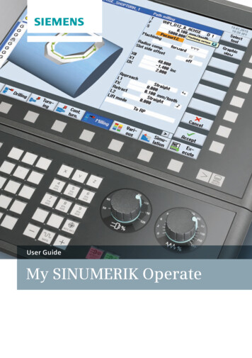
or 3D cross-section view details.The shortcuts for operating the simulation are contained in the appendix.Moldmaking quick viewThe mold making view is available in the editmode for especially large part programs.G0, G1, G2, G3, BSPLINE and POLY lines, VEKTOREN as well as points that can be displayedand hidden are shown.Cycle processing is not shown.Rotary axis as well as vector programming for5-axis programming is supported.The syntax is not checked.SINUMERIK Operate 47
2.14 CNC operation in Automatic mode (AUTO)For the automatic mode, in addition to thetest feedrate and the reduced rapid traverse,y
CNC programming for the highest level of productivity using : . step programming to achieve the shortest programming times in the single-part production. Turning Milling: 16 . In TSM cycle (manual mode), you can, among .