Transcription
SinuTrainBeginner’s Manual: Milling and TurningSINUMERIK 810D / 840D / 840DiTraining Documentation 10/2003SINUMERIK
2nd revised edition Oct. 2003valid for software versions from HMI06.03All rights reservedNo part of this publication may be copied or distributed, transmitted, transcribed, stored in a retrieval system,in any form or by any means, electronic, mechanical, magnetic, manual, or otherwise, or disclosed to thirdparties without the express written permission of the authors.This Beginner’s Manual has been created in cooperation ofSIEMENS AGAutomatisierungs- und AntriebstechnikMotion Control SystemsPostfach 3180, D-91050 ErlangenandR. & S. KELLER GmbHKlaus Reckermann, Siegfried KellerPostfach 13 16 63, D-42043 WuppertalOrder No.: 6FC5095-0AB00-0BP1
PrefaceThe ditigital control systems SINUMERIK 810 D, 840d and 840Di are characterized by their large"openness", i.e. they can be configured by the machine manufacturer and partially also by the userhimself according to their own requirements. They can thus efficiently be used in many fields ofapplication both in the small-series production and in fully automatic manufacturing lines.When creating this Manual, it has been the objective to provide the large range of users an easilyunderstandable access to these powerful control systems.The control systems 810D, 840D und 840Di can be used to control many different machiningprocesses. This Manual deals with the two essential technologies turning and milling.It has been created in cooperation with NC experts and lecturers. We would like to express ourspecial thanks to Mr. Markus Sartor for his valuable hints and criticism.The Manual is practice-oriented and action-oriented. The keys and their use are explained step bystep. The comprehensive presentation of screenshots enables you to compare your own inputs atthe control system with the values and specifications given in this Manual.This Manual can also be used as a preparation or assessment away from the control system withthe control-identical system SinuTrain on the PC.The examples of this Manual were created using mainly Software Version 5.2.Further developments of the software and the already described "openness" of the control system donot exclude that the operation of your control system differs in certain details from the configurationdescribed. It might also happen that - in dependence on the position of the keyswitch on themachine - not all described functions are available. In such cases you are kindly asked to refer to thedocuments of the machine manufacturer or to company-internal documents.We wish you much pleasure and success for the work with your SINUMERIK control system.The authorsErlangen/Wuppertal, in March 20011
810D/840D/840Di Beginner’s ManualTable of Contents1Fundamentals . . . . . . . . . . . . . . . . . . . . . . . . . . . . . . 51.1 Geometric fundamentals of milling and turning . . . . . . . . . . .1.1.11.1.21.1.31.1.41.1.51.1.61.1.7Tool axes and working planes . . . . . . . . . .Absolute and incremental dimensions (milling) .Cartesian and polar dimensions (milling) . . . .Circular movements (milling) . . . . . . . . . .Absolute and incremental dimensions (turning) .Cartesian and polar dimensions (turning) . . . .Circular movements (turning) . . . . . . . . . .5. 5. 8. 9. 10. 11. 12. 131.2 Technical fundamentals of milling and turning . . . . . . . . . . . . 141.2.11.2.21.2.31.2.42Cutting rate and speeds (milling) . . . .Feedrate per tooth and feedrate (milling)Cutting rate and speeds (turning) . . . .Feed (turning) . . . . . . . . . . . . . . 14. 15. 16. 17Operation . . . . . . . . . . . . . . . . . . . . . . . . . . . . . . . 182.1 Overview of the control system . . . . . . . . . . . . . . . . . . . . 182.1.1 Turning on, area switchover, turning off . . . . . . . . . . . . . . . . . . 192.1.2 Keyboard and screen layout . . . . . . . . . . . . . . . . . . . . . . . . 222.2 Setting up . . . . . . . . . . . . . . . . . . . . . . . . . . . . . . . . 282.2.12.2.22.2.32.2.4Tool management: Creating a tool and loading it into the magazineTool compensation: Creating a tool . . . . . . . . . . . . . . . . .Tools of the sample programs . . . . . . . . . . . . . . . . . . . .Scratching the tool and setting zero . . . . . . . . . . . . . . . . . 29. 34. 38. 402.3 Managing and executing programs . . . . . . . . . . . . . . . . . . 432.3.1 Saving data to floppy disk and reading them from floppy disk. . . . . . . 432.3.2 Enabling, loading, selecting and executing a program . . . . . . . . . . 472
810D/840D/840Di Beginner’s Manual3Programming: Milling . . . . . . . . . . . . . . . . . . . . . . . . . 523.1 Workpiece "Longitudinal guide" . . . . . . . . . . . . . . . . . . . . 523.1.13.1.23.1.33.1.43.1.53.1.63.1.7Creating workpiece and part program . . . . . . . . . . . .Tool call and tool change . . . . . . . . . . . . . . . . . .Fundamental functions . . . . . . . . . . . . . . . . . . .Simple traversing paths without cutter radius compensationDrilling using cycles and subroutine technique . . . . . . .Creating a subroutine . . . . . . . . . . . . . . . . . . . .Simulating a program . . . . . . . . . . . . . . . . . . . . 53. 56. 56. 57. 59. 67. 703.2 Workpiece "Injection mold" . . . . . . . . . . . . . . . . . . . . . . 733.2.13.2.23.2.33.2.43.2.54Creating workpiece and part program . . . . . . . . . . . . . . . . .Straight lines and arcs - path milling with cutter radius compensationRectangular pocket POCKET3 . . . . . . . . . . . . . . . . . . . .Circular pocket POCKET4. . . . . . . . . . . . . . . . . . . . . . .Copying a program part . . . . . . . . . . . . . . . . . . . . . . . . 73. 75. 79. 82. 83Programming: Turning . . . . . . . . . . . . . . . . . . . . . . . . 904.1 Workpiece "Shaft". . . . . . . . . . . . . . . . . . . . . . . . . . . . ating workpiece and subroutine . . . . . . . . . . . . . . . .Tool call, cutting rate and fundamental functions . . . . . . . . .Face turning . . . . . . . . . . . . . . . . . . . . . . . . . . . .Cutting cycle CYCLE95 . . . . . . . . . . . . . . . . . . . . . .Finishing . . . . . . . . . . . . . . . . . . . . . . . . . . . . . .Error correction - parallel editing of main program and subroutineThread undercut acc. to DIN76 . . . . . . . . . . . . . . . . . .Thread cutting cycle CYCLE97 . . . . . . . . . . . . . . . . . .Grooving cycle CYCLE93 . . . . . . . . . . . . . . . . . . . . . 91. 981001011021041051071094.2 Workpiece "Complete" . . . . . . . . . . . . . . . . . . . . . . . . 1114.2.14.2.24.2.34.2.4The SINUMERIK contour calculator . . . . . . . .Cutting and finishing of the contour with undercutDrilling centrally . . . . . . . . . . . . . . . . . .End face machining with TRANSMIT . . . . . . .111119120121AppendixIndex . . . . . . . . . . . . . . . . . . . . . . . . . . . . . . . . . . . . . . . . . 126Commands and addresses discussed in this Manual . . . . . . . . . . . . . . . . 128Cycles discussed . . . . . . . . . . . . . . . . . . . . . . . . . . . . . . . . . . . 1283
810D/840D/840Di Beginner’s Manual4
810D/840D/840Di Beginner’s Manual1 FundamentalsThis Chapter provides some general geometric and technological fundamentals for the programming of millingand turning procedures for CNC beginners.1.1Geometric fundamentals of milling and turningThe geometric fundamentals presented here refer mainly to the graphical SINUMERIK contour calculator.The screenshots used in this Manual are intended to support the theory.To understand the theoretical examples provided by the control already in advance:Operating area "Program" Create new part program Horizontal softkey (Contour) in the text editor vertical softkey (Generate contour) .You will find a practical example presenting this contour calculator in the Chapter "Programming/Turning".1.1.1 Tool axes and working planesMILLINGOn universal milling machines the tool is installed in most cases parallel to the main axes. These axes rightangled to each other are aligned according to DIN 66217 or ISO 841 to the main guideways of the machine.The appropriate working plane results from the mounting position of the tool.The Z axis is mostly the tool axis for milling.Tool axis Z - working plane G17If the shown coordinate system is turned correspondingly, the axes and their directions in the associated workingplane will change (DIN 66217).5
1.1- Geometric fundamentals of milling and turningTool axis Y - plane G18Note: It may happen with the softwarerelease of your control system that Z isbefore X in plane G18 due to reasonsof compatibility. This also refers toturning (see below).Tool axis X - plane G19TURNINGOn universal turning machines the tool is installed in most cases parallel to the main axes. These axes rightangled to each other are aligned according to DIN 66217 or ISO 841 towards the main guideways of the machine.The Z axis is mostly the workpiece axis for turning.Rotating axis Z - plane G18 *Since it is relatively easy to control the diameter of turned workpieces, the dimensions of the transverse axisalways refer to the diameter. Thus, the worker can compare the actual dimension directly with the drawingdimensions.Use thetool axis.key to call approriate help screens to select theThe radius dimensionshown here also exists inthe help screenform, butit "hardly never occurs".* All turning operations are programmed in plane G18.Drilling and milling operations at the end face of the turned part are programmed in plane G17.Drilling and milling operations at the peripheral surface of the turned part are programmed in plane G19.6
810D/840D/840Di Beginner’s ManualTo enable a CNC control system, such as the SINUMERIK 840D, to orient itself in the existing working area,there are some important reference points.Machine zero MThe machine zero M is defined by the manufacturer and cannot be changed. When milling, it is inthe origin of the machine coordinate system, and when turning, on the contact surface of the spindlenose.Workpiece zero WThe workpiece zero W, also referred to as the program zero, is the origin of the workpiece coordinatesystem. It can also be freely selected and when milling, it should also be located at a position in thedrawing from which most of the dimensions are measured.When turning, the workpiece zero is always located on the rotary axis and mostly on the plane surfaceReference point RThe reference point R is approached when setting the measuring system, since in most cases themachine zero cannot be approached. The control system will thus find its reference point in theposition measuring system.Toolholder reference point TThe toolholder reference point T is important for setting up with default tools. The lengths L and Qshown in the diagram below are used as tool calculation values and are entered in the tool memoryof the control system.7
1.1- Geometric fundamentals of milling and turning1.1.2 Absolute and incremental dimensions (milling)Absolute inputs:The entered values refer to theworkpiece zero.Incremental inputs:The entered values refer to thecurrent position.**By using the softkey,you can switch over at any time.End pointEnd pointCurrent positionWCurrent positionW*G90 Absolute dimensions*G91 Incremental dimensionsFor absolute inputs, the absolute coordinate valuesof the end point in the active coordinate system mustalways be entered (the current position is not takeninto account).For incremental inputs, the difference valuesbetween the current position and the end point mustalways be entered taking into account the direction.Two examples of the combination absolute/incremental:8
810D/840D/840Di Beginner’s Manual1.1.3 Cartesian and polar dimensions (milling)To define the end point of a straight line, two pieces of data are required, e.g.:Cartesian: Input of the coordinates X and YPolar: Input of the length and of an angleAll hidden values arecalculated anddisplayed automatically.Note:Angle 53.13 starting angle to positive X axisorangle 39.094 angle to previous elementCartesian and polar inputs can be combined, e.g.:Input of the end point in Y and of lengthInput of the end point in X and of an angleThe context-related help screens can be called during the input; theydisplay the names of the individual input boxes.9
1.1- Geometric fundamentals of milling and turning1.1.4 Circular movements (milling)According to DIN, the end point of the arc (coordinates X and Y in the G17 plane) and the center point (I andJ in the G17 plane) have to be indicated for arcs.The SINUMERIK contour calculator also allows you in case of circular arcs to accept any dimension from thedrawing without much conversion.In the following you will find an example with two - at first only partially determined - arcs.Input of the center point (absolute):After input:After input:The following values result if you have entered all known dimensions, and if you have pressed the softkeyin the input window of the respective arc.The inputs of the arcs in the text editor would be:G2 X22.414 Y58.505 I20 J010G2 X105 Y70 I AC(90) J AC(70)
810D/840D/840Di Beginner’s Manual1.1.5 Absolute and incremental dimensions (turning)Absolute input:The entered values refer to theworkpiece zero point.Incremental input:The entered values refer to thecurrent position.Using the softkey, youcan switch over at any time.**End pointEnd pointAttention:CurrentpositionIn contrast to DIN 66025 the diameterrelated I-values are entered anddisplayed when having the valid setting"DIAMON".Currentposition*G90: Absolute dimensions*G91: Incremental dimensionsFor absolute inputs, the absolute coordinate valuesof the end point in the active coordinate system mustalways be entered (the current position is not takeninto account).For incremental inputs, the difference valuesbetween the current position and the end pointmust always be entered taking into account thedirection.Two examples of the combination absolute/incremental:11
1.1- Geometric fundamentals of milling and turning1.1.6 Cartesian and polar dimensions (turning)To define the end point of a straight line, two pieces of data are required. This data can be as follows:Cartesian: Input of the coordinates X and ZPolar: Input of the length and of an angleNote:All hidden values arecalculated and displayedautomatically.End pointEnd pointAngle 126.87 starting angle to positive Z axisorangle -39.094 angle to previous element.(39.094 360 - 320.906 )Cartesian and polar inputs can be combined, e.g.:Input of the end point in X and of the lengthInput of the end point in X and of an angleThe context-related help screens can be called during the input; theydisplay the names of the individual input boxes.121
810D/840D/840Di Beginner’s Manual1.1.7 Circular movements (turning)According to DIN, the end point of the arc (coordinates X and Z in the G18 plane) and the center point(I and K in the G18 plane) have to be specified for arcs.The SINUMERIK contour computer also allows you in case of arcs to accept any dimension from the drawingwithout much conversion.In the following you will find an example with two - at first only partially determined - circular arcs.Input of arc R10:Input of arc R20:After input:After input:The following values result if you have entered all known dimensions, and if you have pressed the softkeyin the input window of the respective arc.The inputs of the arcs in the text editor would be:G2 X50 Z-35 CR 10G3 X30 Z-6.771 I0 K-2013
1.2- Technical fundamentals of milling and turning1.2Technical fundamentals of milling and turning1.2.1 Cutting rate and speeds (milling)The optimum speed of a tool in each individual case depends on the cutting tool material grade, the materialof the workpiece and the tool diameter. In the practice, this speed is also often entered immediately without anycalculations, based on many years of experience. The better way, however, is to calculate the speed from thecutting rate specified in the appropriate tables.Determination of the cutting rate:First, determine the optimum cutting rate on the basis of the manufacturer catalogs or a table book.Cutting tool material grade:Workpiece material:Hard metalC45vc 80 . 150 m/min:The mean value vc 115 m/min should be selected.Calculating the speed:Use this cutting rate and the known tool diameter to calculate the speed n.v c 1000n ---------------------d πThe example below shows how to calculate the speed for two tools:d1 63mmd2 40mm115mm 1000n 1 ---------------------------------------63mm π min115mm 1000n 2 ---------------------------------------40mm π min1n 1 580 ---------minThe NC coding uses the acronym "s" for the speed.In this case, the inputs will be S580 and S900.With these speeds, the cutting rate of 115 m/min is achieved.141n 2 900 ---------min(in the workshop also often referred toas r.p.m.)
810D/840D/840Di Beginner’s Manual1.2.2 Feedrate per tooth and feedrate (milling)On the previous page, you have learned how to determine the cutting rate and how to calculate speeds.To make sure that the tool cuts, a tool feedrate must be assigned to this cutting rate or speed.The basic value of the feedrate is the characteristic quantity "feed per tooth".Determining the feed per tooth:Like the cutting rate, the value for the feed per tooth is also determined using either the table book or theappropriate documents of the tool manufacturer.Cutting tool material grade:Workpiece material:Hard metalC45Feed per tooth fz 0.1 . 0.2 mm:The mean value fz 0.15 mm should be selected.Determining the feedrate:The feedrate vf is calculated using the feed per tooth, the number of teeth and the known speed.vf fz z nThe example below shows how to calculate the feedrate for two tools with a different number of teeth:d1 63mm, z1 4d2 63mm, z2 91v f 2 0, 15mm 9 580 ---------min1v f 1 0, 15mm 4 580 ---------minmmv f 1 348 ---------minmmv f 2 783 ---------minThe NC coding uses the acronym "F" for the feedrate.In this case, the inputs will be rounded off F340 and F780.With these feedrates, the feed per tooth of 0.15 mm is achieved.15
1.2- Technical fundamentals of milling and turning1.2.3 Cutting rate and speeds (turning)Unlike milling, turning generally calls for the desired cutting rate to be programmed directly, namely whenroughing, finishing and plunge-cutting.Only when drilling, and (in most cases) when thread cutting, is the desired speed programmed.Determining the cutting rate:First, determine the optimum cutting rate on the basis of the manufacturer catalog or a table book.Workpiece material:Cutting tool material grade:Free-cutting steelHard metalvc 180 m/min:Constant cutting rate vc (G96) when roughing, finishing and plunge-cutting:To make sure that the selected cutting rate is observed on each workpiecediameter, the appropriate speed is adapted by the control system using thecommand G96 constant cutting rate. This is carried out using either d.c.motors or variable-frequency three-phase motors.With reduced diameter, the speed theoretically increases infinitely. To avoidhazards from excessive radial forces, a speed limit, e.g. of 3,000 r.p.m. mustbe programmed.In this case, the inputs will be G96 S180 LIMS 3000.Constant speed n (G97) when drilling and thread cutting:v c 1000n ---------------------d πd 20mm (tool diameter)120mm 1000n --------------------------------------20mm π min1n 1900 ---------min16Since the speed is constant when drilling,the command G97 constant speed mustbe used here.The speed is dependent on the desiredcutting rate (120 m/min is selected in thiscase) and the tool diameter.In this case, the inputs will be G97 S1900.
810D/840D/840Di Beginner’s Manual1.2.4 Feed (turning)On the previous page, you have learned how to determine the cutting rate and how to calculate speeds.To make sure that the tool cuts, a tool feedrate must be assigned to this cutting rate or speed. The basic valueof the feedrate is the characteristic quantity "feed per tooth".Determining the feed:Like the cutting rate, the value for the feed is also determined using either the table book or the appropriatedocuments of the tool manufacturer or else is based on empirical knowledge.Cutting tool material grade:Workpiece material:Hard metalFree-cutting steelFeed f 0.2 . 0.4 mm:The mean value f 0.3 mm should be selected (in the workshop often referred to as mm per rev.).In this case, the input will be F0.3.Interrelation between feed and feedrate:The constant feed f and the appropriate speed results in the feedrate vf.mv c 180 ---------minvf f nd 2 80mm1n 2 710 ---------minmv c 180 ---------mind 20mm11n 2800 ---------1min1v f 2 710 ---------- 0, 3mmmin1v f 1 2800 ---------- 0, 3mmminmmv f 210 ---------2minvf1mm 840 ---------minSince the speed is different, the feedrate on thedifferent diameters is also different (despite thesame programmed feed).17
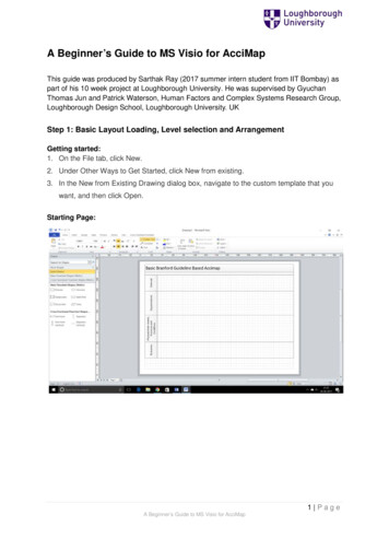
2.1 Operation - Overview of the control system2 OperationIn this manual for beginners the general term "operation" is used for all operating sequences which take placein the direct interaction between user and machine. After a fundamental introduction in Section 2.1, the secondsubsection deals with setting up tools and workpieces. The third and fourth subsections deal mainly with theproduction, i. e. the execution of NC programs.The control systems 810D/840D/840Di are based on an open control concept which allows the machinemanufacturers (and partially also you as the user) to configure the control system according to individualrequirements. That’s why it is possible that there will be differences in the manual as regards the sequencesof action. Please, follow the instructions of the machine manufacturer if necessary, and carefully check yourinputs before you start the machine.2.1Overview of the control systemIn this section, you will learn something aboutstructure and handling of the control systemcomponents "keyboard" and "display".Pictures: OP 010C operator panel front withTFT color screen, softkey bars (horizontal undvertical) and mechanical CNC full keypad with 65keys.These components are used mainly for theprogramming and processing of data. Machine control panel withoverride potentiometersThis control panel influences the machine movementsdirectly.To a certain degree, it can also be configured by themachine manufacturer according to the customer’srequirements.For further operating components for the control system and training keyboards for SinuTrain,please refer to the catalog NC60 "Automation systems for machine tools"(SIEMENS order no. E86060-K4460-A101-A8-7600).18
810D/840D/840Di Beginner’s Manual2.1.1 Turning on, area switchover, turning offDepending on whether you train yourself directly on the machine or whether you use the control-identicalSinumerik training system on the PC, you have to start your work in a different way.Turning onIf.you are working on themachine:Then, of course, first you willhave to look for the main switchlocated either on the side of themachine or on the controlcubicle.If .you are working on the Windows PC:Then you will start the softwarevia the icon on the desktop or viathe entry in the start menu(Start Programs SinuTrain . SinuTrain START).Then you can choose betweenthe two technologies (milling/turning) and the kind of toolmanagement (see Sections2.2.1 and 2.2.2).(With Software Version 6 andhigher, machines can also beconfigured according to thecustomer’s requirements).After turning on, the controlsystem is in the "Machine"operating area, and the "Ref"function (reference pointapproach) is selected.The way how to approach thereference point depends on themachine type and the machinemanufacturer and cantherefore not be be discussedhere in detail.After having started thesoftware, the "Machine"operating area is active and the"Auto" mode is selected.A reference point approach will not besimulated on the PC.The "JOG" mode for direct selection oftraversing axes is not functional on thePC.19
2.1 Operation - Overview of the control systemArea switchoverKeys/inputsScreen / drawingDescriptionBy using the Area switchover key (on the slimline operator panel oron the PCkeyboard), you can - independent of the operating situation you are currently in - unhidethe main menu with the six opreating areas of the control system.The main menu is displayed in theactive Machine operating area. Thesoftkey of the active operating area isselected.In this operating area, you will controlthe machine directly. Here you cantraverse manually, scratch, or run NCprograms.Example: Machining center with three linear axes(X, Y, Z) and 2 rotary axes (A, C)Change with the softkey to theParameter operating area.This can be done on the slimlineoperator panel via the appropriatesoftkey. On the PC, you can click thesoftkey with the mouse or call theoperating area panel with.The Parameters operating area isintended, e.g. to manage your toolsand the table of zero offsets.Example: Magazine list on a turning machine withtool managementActive operating area ’Program(called via softkey, via mouse or).In this operating area, you write andsimulate NC programs.The Chapters 3 (milling) and 4 (turning)explain this in detail.20
810D/840D/840Di Beginner’s ManualKeys/inputsScreen / drawingDescriptionActive operating area ServicesIn this operating area, you can managefiles and read them in and out via theserial interface or a floppy disk.Active operating area DiagnosisAlarm and and service information aredisplayed and documented here.Active Coperating area Start-upAs the name already tells, thisoperating area is intended for systemengineers in order to adapt NC data tothe machine.It is hardly of any importance in thedaily use and will therefore not bediscussed in detail in this Manual.Example: Turning machine with two spindles((.))Depending on the configuration of your system, the7th or 8th softkeys of the main menu can also belabeled; you can use them to call other applications(e.g. AutoTurn).21
2.1 Operation - Overview of the control system()By pressing the Area switchover key ( ) repeatedly, you are able to go back andforth between the two operating areas last active what is quite useful, e.g. whenprogramming to see the tool data in parallel.Just try it with both operating areas "Program" and "Parameters".The "etc. arrow" down on the rightindicates that there are other functionsor applications.By pressing the keyon the slimlineoperator panel or on the PC *,you can extend the menu, and thesoftkeys are reassigned - differentlyaccording to the configuration hold down *, thenPressing the key once again brings youback to the main menu of the operatingareas.Turning offIf .you work on the machine:Please, observe theinstructions of the machinemanufacturer!Trip the main switch todisconnect the system from themains.If .()you work with SinuTrain on the PC:On the extended main menu bar, youwill find a softkey to exit SinuTrain!( PC keyboard: )When quitting the software, all userdata are automatically stored for thenext session.(Alternatives:, see page 26.)2.1.2 Keyboard and screen layoutDuring your first contacts with the user interfaces of the control systems, you have already learnt somethingabout the key Area switchover ( ), the etc. key ( ) and the horizontal softkeys of the main menu. Inthe following, further important keys are introduced to you (using the example of the SinuTrain trainingkeyboard "QWERTY" and the control system screen.22
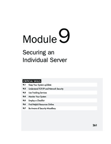
810D/840D/840Di Beginner’s ManualAll keys of the slimline operator panel and ofthe CNC keyboard are integrated in the showntraining keyboard, and in addition, you will alsofind here the most important keys of themachine control panel, which are also used onthe PC.All functions required for working with SinuTraincan be operated directly or via key combinationswith a normal PC keyboard. They are listed inthe following table.2Slimline operator panelKeyPC keysDescription. : By using the horizontal softkeys (numbered from the left to the right), youchange between the operating areas. Within one operating area, you getinto further menu areas and functions which can be called via the verticalsoftkeys.**By using the vertical softkeys (numbered from the top to the bottom), youactivate functions or branch to further subfunctions which are called viathe vertical softkey bar.By using the Area switchover key, the main menu with the operatingareas is displayed. *By using the etc. key, you extend the horizontal softkey bar. *By using Machine area key , you can go directly to the operating area"Machine".The Recall key closes the window on top and lets you return to thehigher-level menu. This function is always available if the key symbolabove the first horizontal softkey is displayed.Hold down *, then press the appropriate F key.23
2.1 Operation - Overview of the control systemCNC full keyboardKeysPC keysDescriptionThe numeric keygroup is used to enter digits and basic arithmeticoperations.In combination with the Shift key (see below), you can enter specialcharacters (?, & .).By using the "QWERTY" keyboard, you enter, e.g. names of partprograms and naturally also NC commands.(The name "QWERTY" arises from the arrangement of the keys.The so-called "DIN" keyboard with alphabetic allocation is often installedat turning machines; the function is identical.) Space key to produce space charactersBy pressing the Shift key, you can call the upper characters on doubleassigned keys and write capital letters (see above).By using the Input key, you can accept an edi
810D/840D/840Di Beginner’s Manual 5 This Chapter provides some general geometric and technologi cal fundamentals for th e programming of milling and turning procedures for CNC beginners. The geometric fundamentals presented here re