Transcription
CHAPTER 3OIL REFINERY PROCESSES
OUTLINE1.2.3.4.5.6.IntroductionPhysical ProcessesThermal ProcessesCatalytic ProcessesConversion of Heavy ResiduesTreatment of Refinery Gas Streams
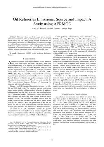
INTRODUCTION Oil refining is a key activity in the ChemicalProcess Industries. Over 600 refineries worldwide have a totalannual capacity of more than 3500 x 106 tones. Goal of oil refining is twofold:i. Production of fuels for transportation, powergeneration and heatingii. Production of raw materials for the CPI.
Crude OilCrude oil is a non-uniform material.The composition depends on its location.Figure 2.11 shows the ratio of C/H in some of chemical compounds
The majority of crude oil is alkanes, cycloalkanes (naphthenes), aromatics,polycyclic aromatics, Sulfur - containing compounds, etc.Example: Gasoline: branched alkanesDiesel: linear alkanes
Heavier crude contains more polycyclic aromatics lead tocarboneceous deposits called “coke”
Some crudes contain a lot of sulfur, which leads toadditional processing considerations.
Overview After desalting and dehydration, crude is separatedinto fractions by distillation. The distilled fractions can not be used directly. The reason for such a complex set of processes is1- the difference between the crude oil propertiesand the needs of the market.2- environmental legislation demands cleaner products3- is the major drive for process improvement anddevelopment of novel processes.
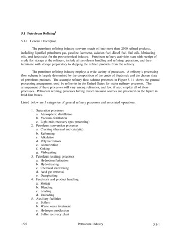
Refining operationsPetroleum refining processes and operations can be separated into fivebasic areas:1. Fractionation (distillation) is the separation of crude oil in atmospheric andvacuum distillation towers into groups of hydrocarbon compounds ofdiffering boiling-point ranges called "fractions" or "cuts."2. Conversion Processes change the size and/or structure of hydrocarbonmolecules. These processes include: : Decomposition (dividing) by thermal and catalytic cracking;Unification (combining) through alkylation and polymerization; andAlteration (rearranging) with isomerization and catalytic reforming.3. Treatment Processes to prepare hydrocarbon streams for additionalprocessing and to prepare finished products. Treatment may includeremoval or separation of aromatics and naphthenes, impurities andundesirable contaminants. Treatment may involve chemical or physicalseparation e.g. dissolving, absorption, or precipitation using a variety andcombination of processes including desalting, drying, hydrodesulfurizing,solvent refining, sweetening, solvent extraction, and solvent dewaxing.
Refining operations4.Formulating and Blending is the process of mixingand combining hydrocarbon fractions, additives, andother components to produce finished products withspecific performance properties.Other Refining Operations include:5. light-ends recovery;sour-water stripping;solid waste, process-water and wastewater treatment;cooling, storage and handling and product movement;hydrogen production;acid and tail-gas treatment;and sulfur recovery.
Refining operations Auxiliary Operations and Facilities include: light steam and power generation;process and fire water systems;flares and relief systems;furnaces and heaters;pumps and valves;supply of steam, air, nitrogen, and other plant gases;alarms and sensors;noise and pollution controls;sampling, testing, and inspecting and laboratory;control room;maintenance; andadministrative facilities.
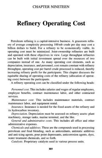
Flow scheme of a modern refinery
Physical and chemical Solvent extractionPropane deasphaltingSolvent gDelayed cokingFlexicokingHydrotreatingCatalytic reformingCatalytic crackingHydrocrackingCatalytic dewaxingAlkylationPolymerizationIsomerization
Physical Processes Desalting/dehydrationCrude distillationPropane deasphaltingSolvent extractionSolvent dewaxingBlending
Desalting/Dehydration1/2 Process Objective: Remove the contaminants in crude oil (often contains water, inorganicsalts, suspended solids, and water-soluble trace metals) so as to reducecorrosion, plugging, and fouling of equipment and to prevent poisoningcatalysts in processing units. Primary Process Technique: The two most typical methods of crude-oil desalting are chemical andelectrostatic separation, and both use hot water as the extraction agent. Process steps: The crude oil feedstock is heated to 65-180 C to reduce viscosity andsurface tension for easier mixing and separation of the water In chemical desalting, water and chemical surfactant (demulsifiers) areadded to the crude, which is heated so that salts and other impuritiesdissolve or attach to the water, then held in a tank to settle out. Electrical desalting is the application of high-voltage electrostatic chargesto concentrate suspended water globules in the bottom of the settling tank.Surfactants are added only when the crude has a large amount ofsuspended solids.
Desalting/Dehydration2/2 The crude oil feedstock is heated to 65-180 C to reduce viscosity andsurface tension for easier mixing and separation of the water. Thetemperature is limited by the vapor pressure of the crude-oilfeedstock. In both methods other chemicals may be added. Ammonia is oftenused to reduce corrosion. Caustic or acid may be added to adjust thepH of the water wash.
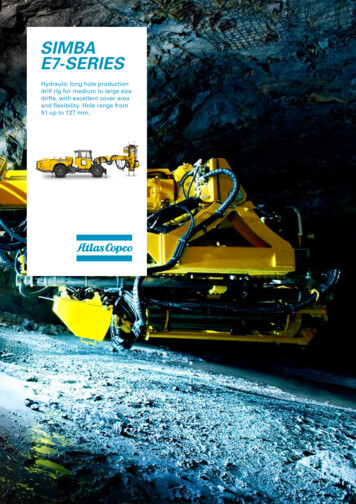
Crude Distillation Step 1 in the refining process is the separation ofcrude oil into various fractions or straight-run cutsby distillation in1- atmospheric and2- vacuum towers.The main fractions or "cuts" obtained have specificboiling-point ranges and can be classified in orderof decreasing volatility into gases, light distillates,middle distillates, gas oils, and residuum.
Fraction of Petroleumb.p. 20oC
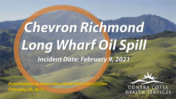
Crude Distillation Unit: Atmospheric distillation1/2 Process Objective: To distill and separate valuable distillates (naphtha, kerosene,diesel) andatmospheric gas oil (AGO) from the crude feedstock. Primary Process Technique: Complex distillation Process steps: Preheat the desalted crude feed by utilizing recovered heat from the productstreams The feedstock then flows to a direct-fired crude charge heater then intothe vertical distillation column just above the bottom, at pressuresslightly above atmospheric and at temperatures ranging from 340-370 C(above these temperatures undesirable thermal cracking may occur).
Crude Distillation Unit: Atmospheric distillation2/2 As the hot vapor rises in the tower, its temperature is reduced. Heavy fuel oil or asphalt residue is taken from the bottom. At successively higher points on the tower, the various majorproducts including lubricating oil, heating oil, kerosene, gasoline,and uncondensed gases (which condense at lower temperatures) aredrawn off. Product draws are on the top, sides, and bottom Utilize pump around cooling loops to create internal liquid reflux
Simple Crude Distillation Unit
Crude Distillation Unit: Vacuum Distillation2/2 Process Objective: To further distill the residuum fromthe atmospheric tower withoutthermal cracking, A typical first-phase vacuum towermay produce gas oils, lubricating-oilbase stocks, and heavy residual forpropane deasphalting Primary Process Technique: Reduced pressure is required. The process takes place in one or morevacuum distillation towers Process steps: Preheat residuum feed in a fired furnace Introduce the feed to a tower at reduced pressureevacuated by a vacuum pumps or ejectors
Modern crude distillation
Propane Deasphalting Process Objective: Coke-forming tendencies of heavierdistillation products are reduced by removalof asphaltenic materials by solvent extraction. Primary Process Technique: Liquid propane is a good solvent(butane and pentane are also commonly used).Deasphalting is based on solubility ofhydrocarbons in propane Process steps: Vacuum residue is fed to a countercurrentdeasphalting tower.Alkanes dissolve in propane whereas asphaltenicmaterials (aromatic compounds), ‘cokeprecursors’ do not.Asphalt is sent for thermal processing.
Propane Deasphalting
Solvent Extraction and Dewaxing Solvent treating is a widely used method of refining1- lubricating oils2- a host of other refinery stocks. Since distillation (fractionation) separates petroleum products intogroups only by their boiling-point ranges, impurities may remain.These include organic compounds containing sulfur, nitrogen, andoxygen; inorganic salts and dissolved metals; and soluble saltsthat were present in the crude feedstock. In addition, kerosene and distillates may have trace amounts ofaromatics and naphthenes, and lubricating oil base-stocks maycontain wax. Solvent refining processes including solvent extraction andsolvent dewaxing usually remove these undesirables atintermediate refining stages or just before sending the product tostorage.
Solvent Extraction 1/3 Process Objective: to prevent corrosion, protect catalyst in subsequent processes, and improvefinished products by removing unsaturated, aromatic hydrocarbons fromlubricant and grease stocks. Primary Process Technique: The solvent extraction process separates aromatics, naphthenes, andimpurities from the product stream by dissolving or precipitation. The most widely used extraction solvents are phenol and furfural. Process steps: In one type of process, the feedstock is washed with furfural in which thesubstances to be removed are more soluble than in the desired resultantproduct. The solvent is separated from the product stream by heating, evaporation,or fractionation, and residual trace amounts are subsequently removedfrom the raffinate by steam stripping or vacuum flashing. The solvent is regenerated for reused in the process.
Solvent Extraction 2/3Aromatic Solvent Extraction Unit
Solvent Extraction 3/3 In another process, selected solvents are added to causeimpurities to precipitate out of the product. In the adsorption process, highly porous solid materialscollect liquid molecules on their surfaces Electric precipitation may be used for separation ofinorganic compounds. The most widely used extraction solvents are phenol,furfural, and cresylic acid. Other solvents less frequently used are liquid sulfur dioxide,nitrobenzene, and 2,2' dichloroethyl ether. The selection of specific processes and chemical agentsdepends on the nature of the feedstock being treated, thecontaminants present, and the finished product requirements.
Solvent Dewaxing Process Objective: Solvent dewaxing is used to remove wax from either distillate orresidual base stock at any stage in the refining process. Primary Process Technique: Usually two solvents are used: toluene, which dissolves the oil andmaintains fluidity at low temperatures, and methyl ethyl ketone(MEK), which dissolves little wax at low temperatures and acts as awax precipitating agent. Other solvents sometimes used includebenzene, methyl isobutyl ketone, propane, petroleum naphtha,ethylene dichloride, methylene chloride, and liquid sulfur dioxide. Process steps:There are several processes in use for solvent dewaxing, but all havethe same general steps, which are: Mixing the feedstock with a solvent; Precipitating the wax from the mixture by chilling; Recovering the solvent from the wax and dewaxed oil for recyclingby distillation and steam stripping.
Solvent Dewaxing Unit
Blending Process Objective: Blending is the physical mixture of a number of different liquidhydrocarbons to produce a finished product with certain desiredcharacteristics. Primary Process Technique: Products can be blended in-line through a manifold system, orbatch blended in tanks and vessels. Additives including octane enhancers, anti-oxidants, anti-knockagents, gum and rust inhibitors, detergents, etc. are added duringand/or after blending to provide specific properties not inherentin hydrocarbons. Process steps: In-line blending of gasoline, distillates, jet fuel, and kerosene isaccomplished by injecting proportionate amounts of eachcomponent into the main stream where turbulence promotesthorough mixing.
THERMAL PROCESSES When a hydrocarbon is heated to a sufficiently hightemperature thermal cracking occurs. This is sometimesreferred to as pyrolysis (especially when coal is thefeedstock). When steam is used for heating it is called steamcracking. There are two thermal processes used in refineries. Visbreaking Delayed coking
Visbreaking 1/2Visbreaking is a mild form of thermal cracking to lowerthe viscosity Process Objective: Lowers the viscosity of heavy crude-oil residues without affecting theboiling point range. Reduce the pour point of waxy residues and reduce the viscosity ofresidues used for blending with lighter fuel oils. Primary Process Technique:Visbreaking is a mild form of thermal cracking for which oil isheated to a sufficiently high temperature Process steps: Residuum from the atmospheric distillation tower is heated (425-510ºC) atatmospheric pressure and mildly cracked in a heater. It is then quenched with cool gas oil to control over-cracking, and flashedin a distillation tower.
Visbreaking 2/2 Alternatively, vacuum residue can be cracked. The severity of thevisbreaking depends upon temperature and reaction time (1-8 min). Usually 10 wt% of gasoline and lighter products are produced.
Delayed Coking Process 1/3 Coking is a severe method of thermal cracking used to upgrade heavyresiduals into lighter products or distillates. Coking produces straight-run gasoline (Coker naphtha) and various middledistillate fractions used as catalytic cracking feedstock. The process completely reduces hydrogen so that the residue is a form ofcarbon called "coke." Three typical types of coke are obtained (sponge coke, honeycomb coke, andneedle coke) depending upon the reaction mechanism, time, temperature, andthe crude feedstock. In delayed coking the heated charge (typically residuum from atmosphericdistillation towers) is transferred to large coke drums which provide the longresidence time needed to allow the cracking reactions to proceed tocompletion.
Delayed Coking Process 2/3 Process Objective: To convert low value residue to valuable products such as naphthaand diesel and gas oil (ie used to upgrade heavy residuals intolighter products or distillates ). Primary Process Technique: The process completely reduces hydrogen so that the residue is aform of carbon called "coke." in a semi batch process.
Delayed Coking Process 3/3 Process steps: In delayed coking, the heated residuum from atmospheric towers istransferred into large coke drums which provide the long residencetime needed to allow the cracking reactions to proceed to completion. The bottoms of the fractionator are fed to coker drums via a furnacewhere the hot material (440 -500 C) is held approximately 24 hours(delayed) at pressures of 2-5 bar, until it cracks into lighter products. Vapors from the drums are returned to a fractionator where gas,naphtha, and gas oils are separated out. The heavier hydrocarbonsproduced in the fractionator are recycled through the furnace. After the coke reaches a predetermined level in one drum, the flow isdiverted to another drum in order to maintain continuous operation. To strip out uncracked hydrocarbons, the full drum is steamed, cooledby water injection, and de-coked by mechanical or hydraulic methods. The coke is mechanically removed by an auger rising from the bottomof the drum. Hydraulic decoking consists of fracturing the coke bedwith high-pressure water ejected from a rotating cutter.
Delayed Coking/ Process Schematic
CATALYTIC PROCESSESThere are several types of catalytic processes used inrefineries. Fluid Catalytic Cracking (FCC) Hydrotreating Hydrocracking Catalytic Reforming Alkylation
Fluid Catalytic Cracking1/3 Process Objective: To convert low value gasoil to valuable products (gasoline, naphtha and diesel) Primary Process Technique: Catalytic cracking increases H/C ratio by carbon rejection Thermal cracking occurs on the surface of the catalyst in a continuous process. Process steps: Gas oil feed and catalyst are dispersed into the bottom of the riser using steam Oil is cracked in the presence of a finely divided catalyst, which is maintained in anaerated or fluidized state by the oil vapours. Preheated feed is mixed with hot, regenerated catalyst in the riser and combinedwith a recycle stream, vapourized, and raised to reactor temperature (485-540 C) bythe hot catalyst As the mixture travels up the riser, the charge is cracked at 0.7-2 bar. The fluid catalyst is continuously circulated between the reactor and the regeneratorusing air, oil vapors, and steam as the conveying media.
Fluid Catalytic Cracking2/3 Disengaging drum separates spent catalyst from product vapors Steam strips residue hydrocarbons from spent catalyst Spent catalyst flows through the catalyst stripper to the regenerator,where most of the coke deposits will burn off at the bottom wherepreheated air and spent catalyst are mixed. Fresh catalyst is added and worn-out catalyst removed to optimizethe cracking process. Regenerated catalyst enters bottom of riser-reactor
Fluid Catalytic Cracking3/3
Fluidic Catalytic Cracking-Process SchematicProducts to FractionationDisengagingVesselFlue Gas(CO2, CO, AirGas Oil FeedDispersant Steam
Fluid Catalytic Cracking- Full Process
Hydrotreating Processes1/2 Catalytic hydrotreating is a hydrogenation process used to removeabout 90% of contaminants such as nitrogen, sulfur, oxygen, andmetals from liquid petroleum fractions. Such as Remove NH3 Also, catalytic hydrotreating converts olefins and aromatics tosaturated compounds, such as: Typically, hydrotreating is done prior to processes such as catalyticreforming so that the catalyst is not contaminated by untreatedfeedstock.
Hydrotreating Processes2/2 Process Objective: To remove contaminants (sulfur, nitrogen, metals) and saturate olefins and aromaticsto produce a clean product for further processing or finished product sales. Primary Process Technique: Hydrogenation occurs in a fixed catalyst bed to improve H/C ratios and to removesulfur, nitrogen, and metals. Process steps: Feed is preheated using the reactor effluent Hydrogen is combined with the feed and heated to the desired hydro-treatingtemperature using a fired heater (at 285-34O0C) Feed and hydrogen pass downward in a hydrogenation reactor packed with varioustypes of catalyst depending upon reactions desired (such as cobalt or nickeloxide/molybdenum oxide catalyst) Reactor effluent is cooled and enter the high pressure separator which separates theliquid hydrocarbon from the hydrogen/hydrogen sulfide/ammonia gas Acid gases are absorbed from the hydrogen in the amine absorber Hydrogen is recycled with make-up hydrogen Further separation of LPG gases occurs in the low pressure separator prior tosending the hydrocarbon liquids to fractionation
Hydrotreating: flow scheme
Hydrotreating Processes Naphtha Hydrotreating Primary objective is to remove sulfur contaminant for downstream processes;typically 1wppm Gasoline Hydrotreating Sulfur removal from gasoline blending components to meet recent clean fuelsspecifications Mid-Distillate Hydrotreating Sulfur removal from kerosene for home heating Convert kerosene to jet via mild aromatic saturation Remove sulfur from diesel for clean fuels FCC Feed Pretreating Nitrogen removal for better FCC catalyst activity Sulfur removal for Sulfur oxide reduction in the flue gas and easier post-FCCtreatment Aromatic saturation improves FCC feed “crackability” Improved H/C ratios increase FCC capacity and conversion
Hydrocracking Hydrocracking is a two-stage process combining catalytic cracking andhydrogenation, wherein heavier feedstock is cracked in the presence ofhydrogen to produce more desirable products. The process employs (1) high pressure, (2) high temperature, (3) acatalyst, and (4) hydrogen. Hydrocracking is used for feedstock that are difficult to process by eithercatalytic cracking or reforming, since these feedstock are characterizedusually byi) a high polycyclic aromatic contentii) high concentrations of the two catalyst poisons: sulfur and nitrogen The process largely depends on the nature of the feedstock and therelative rates of the two competing reactions: hydrogenation andcracking. Heavy aromatic feedstock is converted into lighter products under a widerange of very high pressures (70-140 bar) and fairly high temperatures(400 -800 C), in the presence of hydrogen and special catalysts.
Hydrocracking Process Process Objective: To remove feed contaminants (nitrogen & sulfur) and to convert low value gas oilsto valuable products (naphtha, middle distillates, and ultra-clean lube base stocks). Primary Process Technique: Hydrogenation occurs in fixed hydrotreating catalyst beds to improve H/C ratiosand to remove sulfur, nitrogen, and metals. This is followed by one or morereactors with fixed hydrocracking catalyst beds to dealkylate aromatic rings, opennaphthene rings, and hydrocrack paraffin chains. Process steps: Preheated feed is mixed with hot hydrogen and passes through a multi-bed reactorwith inter-stage hydrogen quenches for hydrotreating The catalysts convert sulfur and nitrogen compounds to H2S and NH3. Limitedhydrocracking also occurs. Reactor effluents are combined and pass through high and low pressure separatorsand are fed to the fractionator where valuable products are drawn from the top,sides, and bottom Fractionator bottoms may be recycled to a second pass hydrocracker for additionalconversion all the way up to full conversion the operations of the second stage aremore severe (higher temperatures and pressures). Again, the second stage productis separated from the hydrogen and charged to the fractionator
Hydrocracking Flow Scheme
Catalytic Reforming Catalytic reforming is an important process used to convert lowoctane naphthas into high-octane gasoline blending componentscalled reformates. Reforming represents the total effect of numerous reactions such ascracking, polymerization, dehydrogenation, and isomerization takingplace simultaneously. Depending on the properties of the naphtha feedstock (as measuredby the paraffin, olefin, naphthene, and aromatic content) and catalystsused, reformates can be produced with very high concentrations ofbenzene, toluene, xylene, (BTX) and other aromatics useful ingasoline blending and petrochemical processing. Hydrogen, a significant by-product, is separated from the reformate forrecycling and use in other processes.
Catalytic Reforming
Catalytic Reforming Most processes use Pt as the active catalyst. SometimesPt is combined with a second catalyst (bimetallic catalyst)such as rhenium. There are many different commercial processes includingplatforming, powerforming, ultraforming, and Thermoforcatalytic reforming. Some reformers operate at low pressure (3-13 bar),others at high pressures (up to 70 bar). Some systemscontinuously regenerate the catalyst than in other systems.One reactor at a time is taken off-stream for catalystregeneration
Catalytic Reforming Process Process Objective: To convert low-octane naphtha into a high-octane reformate for gasolineblending and/or to provide aromatics (benzene, toluene, and xylene) forpetrochemical plants. Reforming also produces high purity hydrogen forhydrotreating processes. Primary Process Technique: Reforming reactions occur in chloride promoted fixed catalyst beds; orcontinuous catalyst regeneration (CCR) beds where the catalyst istransferred from one stage to another, through a catalyst regenerator andback again. High temperatures with typical catalysts of platinum and/orrhenium on alumina and short contact times are used Desired reactions include: dehydrogenation of naphthenes to formaromatics; isomerization of naphthenes; dehydrocyclization of paraffinsto form aromatics; and isomerization of paraffins. Hydrocracking of paraffins is undesirable due to increased light-endsmake.
Process steps: In the platforming process, the naphtha feedstock is mixed with recycledhydrogen, vaporized , and passed through a series of alternating furnaceand fixed-bed reactors containing a platinum catalyst. Each pass requires heat input to drive the reactions The effluent from the last reactor is cooled and sent to a separator topermit removal of the hydrogen-rich gas stream from the top of theseparator for recycling. The liquid product from the bottom of the separator is sent to afractionator called a stabilizer (butanizer). It makes a bottom productcalled reformate; butanes and lighter go overhead and are sent to thesaturated gas plant.
Catalytic Reforming/ Process Schematic3rd Pass Reactor2nd Pass Reactor1st Pass ReactorNaphtha Feed1st Pass HeaterHigh PurityHydrogen2nd Pass Heater3rd Pass HeaterRecycle CompressorLPGHP SeparatorLP SeparatorReformate toFractionation
Catalytic reforming reactors
Alkylation Alkylation combines low-molecular-weight olefins(primarily a mixture of propylene and butylene) withisobutene in the presence of a catalyst, either sulfuricacid or hydrofluoric acid. The product is called alkylate (gasoline) and iscomposed of a mixture of high-octane, branched-chainparaffinic hydrocarbons. Alkylate is a premium blending stock because it hasexceptional antiknock properties and is clean burning.The octane number of the alkylate depends mainlyupon the kind of olefins used and upon operatingconditions.
Sulphuric acid alkylation process In cascade type sulfuric acid (H2SO4) alkylation units, the feedstock(propylene, butylene, amylene, and fresh isobutane) enters thereactor and contacts the concentrated sulfuric acid catalyst (inconcentrations of 85% to 95% for good operation and to minimizecorrosion). The reactor is divided into zones, with olefins fed through distributorsto each zone, and the sulfuric acid and isobutanes flowing over bafflesfrom zone to zone. The reactor effluent is separated into hydrocarbon and acidphases in a settler, and the acid is returned to the reactor. The hydrocarbon phase is hot-water washed with caustic for pHcontrol before being successively depropanized, deisobutanized, anddebutanized. The alkylate obtained from the deisobutanizer can then go directly tomotor-fuel blending or be re-run to produce aviation-grade blendingstock. The isobutane is recycled to the feed.
Sulphuric acid alkylation process
HF Alkylation Process Process Objective: To combine light olefins (propylene and butylene) with isobutane to form a high octanegasoline (alkylate). Primary Process Technique: Alkylation occurs in the presence of a highly acidic catalyst (hydroflouric acid or sulfuricacid). Process steps: Olefins from FCC are combined with Iso-Butane and fed to the HF Reactor wherealkylation occurs Acid settler separates the free HF from the hydrocarbons and recycles the acid back to thereactor A portion of the HF is regenerated to remove acid oils formed by feed contaminants orhydrocarbon polymerization Hydrocarbons from settler go to the De-Isobutanizer for fractionating the propane andisobutane from the n-butane and alkylate Propane is then fractionated from the isobutane; propane as a product and the isobutane tobe recycled to the reactor N-Butane and alkylate are deflourinated in a bed of solid adsorbent and fractionated asseparate products
HF Alkylation/ Process SchematicStripped HFOlefin Feed& IsobutaneIsobutane RecycleReactorHF esh AcidN-ButaneHF RegeneratorDebutanizerAcid OilsDeflourinatorAlkylate
TREATMENT OF REFINERY GASES Removal of H2S from gases is usually performed by absorption inthe liquid phase. The concentrated H2S is frequently converted to elemental sulphurby the “Claus” process. In the Claus process 95-97% of the H2S is converted. H2S is often removed with solvents that can be regenerated, usuallyalkanolamines: e.g. CH2(OH)CH2NH2 MEA (mono-ethanolamine). These amines are highly water soluble with low volatility and theirreaction with H2S is much faster than with CO2 so that the amountof absorbed CO2 can be limited by selecting appropriate conditions.
Oil refining is a key activity in the Chemical Process Industries. Over 600 refineries worldwide have a total annual capacity of more than 3500 x 106 tones. Goal of oil refining is twofold: i. Production of fuels for transportation, power generation and heating ii. Production of raw materials for the CPI.