Transcription
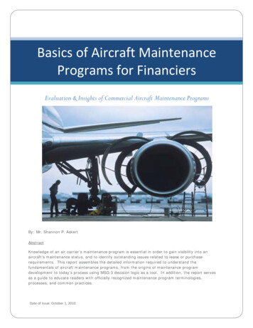
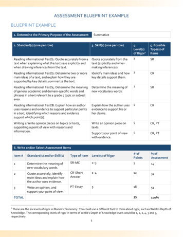
Aircraft Drawing and BlueprintReading
Course Introduction Types of drawings– Engineering – also known as production orworking drawings.– Block diagram
Types of Drawings– Schematics– Sketches– Charts and graphs
Production Drawings Detail Assembly Installation
Detail Drawing Consists of onepart or severalparts of anassembly. Contains all thespecs neededto make thepart.
Assembly Drawing Shows how partsfrom detail drawingsare assembled toform a component. Does not showdimensions exceptthose necessary forlocation purposes.Cut-Away View
Assembly DrawingExplodedView
Installation Drawing Shows how apart orcomponent isinstalled in theaircraft. Location anddirectionaldimensions areincluded.
Block Diagrams Used to simplifycomplex circuits Shows thefunction andrelationships ofvariouscomponents withina system.
Schematics Like blockdiagrams, theyare used toexplain asystem. More detailedthan a blockdiagram.
SchematicsNot all schematics are electrical
Sketches Anything from a scribble on a cocktailnapkin to a detailed engineering drawing.– One should strive to develop the skill toproduce a rendering that is as accurate andclean as possible.
Charts and Graphs Are used to aid in the presentation of data,especially mathematical data.
Charts and Graphs Charts and graphshelp in theunderstanding ofaircraft operationsand can sometimeoffer shortcuts tomathematicalcalculations.
Lettering Accurate and legible drawings requireuniform and legible lettering. Lettering should receive the same attentionto detail as does the drawing itself.
LetteringEach letter should be 6 units high.All letters are either 5 or 6 units wide.The exceptions are “I”, which has nowidth, and “W”, which is the widest letterof the alphabet.
Lettering Those letters that are 6 units wide makeup the name “TOM Q VAXY” All others, with the exception of “I” and“W”, are 5 units wide. “W” is 8 units wide and “I” is one unit wide.
LetteringDo not space letters equal distances apart.Space by eye so that the background areasbetween the letters appear equal.
Projections and Lines Projections help us to see a 3-dimensionalobject using a 2-dimensional medium. Different views are used to highlightdifferent objectives for each drawing.
Types of Projections Perspective drawings– In a perspective drawing parallel lines areshown converging as they recede into thepicture.– This effect is known as foreshortening
Types of Projections Not accurate for dimensioning, perspectivedrawings are used for overall views andproviding location information.
Types of Projections Oblique views– Parallel lines areparallel anddimensions ofsides are accurate.– Front face is drawnin true size andshape.
Types of Projections Isometricprojections– Similar to obliqueviews but not asdistorted.– Horizontal lines aredrawn at a 45 or30 /60 angle.
Types of Projections Orthographicprojections– Presents an objectusing a series ofviews from differentsides.– Front, top, and rightside views are mostcommon.
Lines Three widthsof lines used wide, medium,and narrow
Dimensioning Used for determining the size or locationof an object. Indicated by numbers followed by units ofdimension e.g. ft, mm, etc.
Dimensioning If no unit is present then the dimension isin inches. Dimensions may be in decimal form or infractions.
Dimensioning Tolerance – total permissible variation insize. ( ) and (-) signs are used, followed by thedimension, either in units or %. Example:.005 inches or5%
Dimensioning Allowance – prescribed differencebetween the maximum material limits ofmating parts.– Classes of fit from positive (loose or sliding) tonegative (tight or interference).
Dimensioning Placement of dimensions Draw the dimension line outside of theobject, if possible.CorrectIncorrect
Dimensioning Draw the shortest dimension lines closestto the object and the longest lines furthestaway.
Orthographic Projections Using different views to look head-on ateach side of an object. The number of views are dictated by thecomplexity of the object.
Orthographic Projections Anywhere fromone to six viewsare possible. Front, top, rightside, left side,rear, bottom.
Orthographic Projection Most common:– Single view – front– 2 view – front, top– 3 view – front, top, right side Sides are referenced from the front, asyou look at it.
Orthographic Projections Only those views needed to describe theobject’s shape should be drawn. Views should be laid out in a standardizedfashion, with proper spacing andalignment among the views.
Drawing 3-Views Any given point in the drawing will show inall views.
Drawing 3-Views Lines thatcoincide. A solid linecovers a hiddenline.
Drawing 3-Views A solid linecovers acenterline. A hidden linecovers acenterline.
Drawing Three-viewsAdding a Title BoxPlace in Lower right corner ½” from the edge
Isometric Projections An effective way to sketch an objectpictorially. Object is dimensionally correct but hassome distortion in viewing.
Maximum Material Condition Definition: a part manufactured to the limitof its tolerance which leaves the mostmaterial on the part. MMC is often used to determine the fit oftwo interconnecting parts in their closesttolerance
Maximum Material Condition Example 1: a dowel whose diameter is1.000” .005” would have a maximummaterial condition of 1.005”
Maximum Material Condition Example 2: a hole in a part whosediameter is 1.000” .005” would have amaximum material condition of 0.995”
Allowance Definition: the difference in dimensionbetween the maximum material conditionsof two interconnecting parts Allowance can be positive (clearance fit)or negative (interference fit).
Allowance
SpacingHoles
Locatingbolt holeswithout aprotractor
Charts
Graphs
Graphs
Graphs
Maximum Material Condition Definition: a part manufactured to the limit of its tolerance which leaves the most material on the part. MMC is often used to determine the fit of