Transcription
PTC/USER 2009Pro/ENGINEER Wildfire 5.0Hands On WorkshopWORKSHOP USE ONLYPlease do not write notes in this book or removefrom the workshop. It will be used by all participants.
PTC/USER 2009Table of ContentsInteractive Modeling . 3UUMolded Part Design Efficiency . 16UUSheet Metal Design & Welding . 22UUFlexible Assembly . 36UUSimulation . 46UUDrawing Workflow and Efficiency . 59UUPro/ENGINEER Manikin. 71UUTolerance Analysis . 78UUPro/ENGINEER Wildfire Hands On WorkshopPage 1
PTC/USER 2009CAD FilesThe CAD files required for this tutorial can be download from this dfire5/tutorial/wf5 how student v2.zipHUUDocument Format & PrintingThis document is setup to be printed with (2) pages per sheet to minimize the totalnumber of printed pages. If available, please setup your printer for multi‐page printing.ConventionsInformation is provided at the start of many tasks.Tips are provided along the way, with time‐saving or alternate techniques.Notes are provided with additional useful details, which may not be required tocomplete the tutorial. Menu commands are shown in BoldThe comma character , is as a separator between commandsIcons are shown in line with command textKeyboard keys are shown in Bold CAPSThe left, middle and right mouse buttons are referred to as LMB, MMB, RMBPro/ENGINEER Wildfire Hands On WorkshopPage 2
PTC/USER 2009Interactive Modeling0BThis tutorial will cover some of the new sketcher, feature and edit functionsin Pro/ENGINEER along with placement of User Defined Features (UDF) andthe Model Properties dialog box.New Sketcher Functions8B1. File, Open, INTERACTIVE‐MODELING folder, select housing.prt, OpenActual exercise model color may be different to improve contrast in sketcher1. Select Sketch, select the surface shown below (with the hole) as the sketchplane, Sketch, toggle on No HiddenPro/ENGINEER Wildfire Hands On WorkshopPage 3
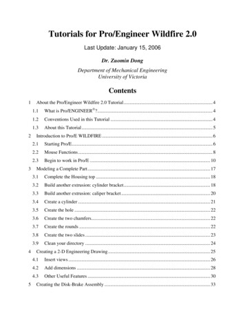
PTC/USER 2009New sketching tools can directly create a slanted rectangle and a slantedellipse, providing flexibility and speed in feature creation.2. Select the fly‐out arrow next toand select Slant Rectangle , sketch aslanted rectangle in the sketch plane, do NOT snap the rectangle to anyreferences3. Pick the fly‐out arrow next toand select Center and Axis Ellipse , start atmid‐point of the width, end at the corner as shown, LMB to finish the ellipse4. Select Chamfer , select the adjacent entities for length and width as shownbelow, MMB to finishPro/ENGINEER Wildfire Hands On WorkshopPage 4
PTC/USER 20095. Hold Ctrl and select the chamfer and the adjacent entity shown, RMB, review allobject‐action constraints, EqualSketcher constraints and workflows are more flexible. There are shortcutmenus, object‐action workflow, and a consolidated user interface.6. Select Delete Segment, delete unnecessary sketch entities as shownPro/ENGINEER Wildfire Hands On WorkshopPage 5
PTC/USER 2009In the follow tasks, make sure to use the fly‐out to select GeometryCenterline or Point. These are different than regular sketchercounterparts. Depending on how the sketch is used, they can producedatum features in the model.7. Select the fly‐out arrow next toand select Geometry Centerlinegeometry centerline snapped to two corners as shown below8. Select the fly‐out arrow next toand select Geometry Pointat any position inside the sketch, MMB to confirm9. Select Done, sketch a, sketch a pointto finish sketchPro/ENGINEER Wildfire Hands On WorkshopPage 6
PTC/USER 200910.Toggle on Shading displayAxisand Datum Point, Named View List, sketcher, toggle on Datum, review the datum axis and the datum point createdin the Sketcher, toggle off Datum Axisand Datum Point11.Pick Extrude , select the sketch just created, RMB on the depth control handle ,Symmetric, change the depth to 1.00, MMB to finish12.Toggle Axis Display, note that the Geometry Point resulted in a Datum Axis,toggle off the Axis DisplayPro/ENGINEER Wildfire Hands On WorkshopPage 7
PTC/USER 2009Undo/Redo9BSome operations will clear the stack. If you do not see the exact list asshown below, experiment with a few operations and/or the choicesavailable.1. Select the arrow next to2. Select the arrow nextUndo and select Undo: SketchRedo and select Redo: ExtrudeDynamic Edit10BYou can use the Dynamic Edit command to edit features and immediatelysee the impact of dimensional changes on the model geometry. Use the 3Ddrag handles on the section to move the entire section. Note thatconstraints are enforced.Pro/ENGINEER Wildfire Hands On WorkshopPage 8
PTC/USER 20091. Select Round , RMB on an intersection edge between the extrude feature andthe box wall, Pick From List2. Select the Intent Edges from list for two loops from intersection of extrusion andthe base model, OK3. Change the round radii to 0.12, MMB to confirm4. Select the extrude feature just created in the Model Tree or in the graphicswindow, RMB Dynamic Edit, select 3D drag handle where the cursor points asshown belowPro/ENGINEER Wildfire Hands On WorkshopPage 9
PTC/USER 20095. Move the entire feature towards the hole, review the dynamic changes6. LMB on the graphic window to exit the dynamic editPro/ENGINEER Wildfire Hands On WorkshopPage 10
PTC/USER 2009Failure and DiagnosticsIn Pro/ENGINEER Wildfire 5.0, you can deal with failures now or later, andmodels can now be saved with failed features. “Failed” geometry is shownwhen possible.1. Named View List , No Resolve, select the BOSS 1 protrusion feature in theModel Tree, RMB Dynamic Edit, RMB in the graphics window, checkShow/Hidden All Dims2. Drag the dim R.13 control handle where the cursor points, dynamically changethe cut narrower until the feature fails and becomes red, LMB in the graphicswindow to exitPro/ENGINEER Wildfire Hands On WorkshopPage 11
PTC/USER 2009There is no resolve mode in Pro/ENGINEER Wildfire 5.0. You are given awarning and options to fix the failing feature(s).3. Click OK to accept the result and we will fix the fails later on, review the failedfeatures highlighted in the Model Tree4. Select BOSS 1 feature in the Model Tree, RMB Edit Definition, click Placement inthe dashboard, Edit , drag and redefine the sketch until no intersected entitiesDynamic Edit can be used again for this step5. Select Done,confirm, review the resolved featuresPro/ENGINEER Wildfire Hands On WorkshopPage 12
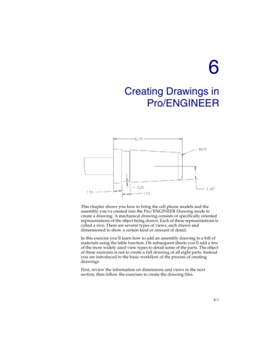
PTC/USER 2009User Defined Feature (UDF)1BYou can place user‐defined feature (UDFs) using the new on‐surfacecoordinate system as a reference. You can preview the UDF geometry as itis being placed on the model, and also can see an immediate display ofchanges in variable dimensions and even specify additional rotations aboutthe placement coordinate system1. Toggle on Csys Display, Insert, User‐Defined Feature , browse toINTERACTIVE‐MODELING folder and select boss udf.gph, Open2. Check View source model option, resize the BOSS UDF GP window, OK, pick theboss surface to specify the placement reference, toggle off Annotation display3. Drag the two green placement handles to specify the location references4. Drag the location handle and move, review the immediate udpatesPro/ENGINEER Wildfire Hands On WorkshopPage 13
PTC/USER 20095. Select Variables tab, change the rib instance from 3 to 6, Enter, preview thechanges of UDF boss in the graphics window6. Select Options, Adjustments tabs to review options, select, toggle off CsysDisplayModel Properties12BModel properties, such as materials, units, and accuracy, are located on acommon Model Properties dialog box. This new dialog box also containsinformation on relations and parameters used in the model.1. File, Properties, review all options of Model Properties2. Select Change next to Material, RMB on the steel.mtl in the left column, Assign,OK, Close the Model Properties windowPro/ENGINEER Wildfire Hands On WorkshopPage 14
PTC/USER 20093. Window, Close4. File, Erase, Not DisplayedPro/ENGINEER Wildfire Hands On WorkshopPage 15
PTC/USER 2009Molded Part Design Efficiency1BThis tutorial will show some the new features and enhancements to assist inthe design of cast and molded parts including geometry patterns, the newtrajectory rib feature and enhancements to draft check analysis.Pattern Enhancements13B1. File, Open, PART‐MOLDED folder, gearbox.prt, Open2. Select Hole 1 in the Model Tree, PatternPro/ENGINEER Wildfire Hands On WorkshopPage 16
PTC/USER 20093. On dashboard, select Point from the drop‐down list for type, then the Use Pointsoption. In the Model Tree select Datum Point 7012, MMB or4. In Model Tree, select Chamfer 1, Pattern, ensure that the type is Reference,MMB orIn the next step, it may be helpful to change the smart filter to Geometry.Refer to the Quick Reference card for guidance on this type of selection.5. Select geometry using “surface and boundaries” technique. Pick top surface ofthe protrusion shown, then Shift Pick the shell at base of the protrusion.6. Edit, Geometry PatternGeometry patterns make regeneration faster as compared to patterningthe entire feature definition.Pro/ENGINEER Wildfire Hands On WorkshopPage 17
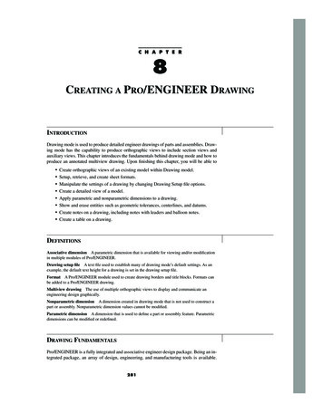
PTC/USER 20097. Dashboard, Axis, select GEOMETRY PATTERN AXIS in Model Tree, enter 5 fornumber of pattern members, Angular Extent, enter 180, MMB orTrajectory Rib Tool14B1. In Model Tree, select sketch RIB1, pick Trajectory Rib0.1 for the thickness, select Draft iconin the dashboard enter, Internal Rounds, External Rounds2. Select Shape tab and enter 1 for the draft value, and 0.05 for internal rounds, andTwo‐Tangent round, MMB orPro/ENGINEER Wildfire Hands On WorkshopPage 18
PTC/USER 20093. In Model Tree, select Trajectory Rib 1, Copy, Paste, in the Model Tree,select sketch RIB2,4. Paste, in the Model Tree, select sketch RIB3,Pro/ENGINEER Wildfire Hands On WorkshopPage 19
PTC/USER 2009Draft Analysis15B1. Analysis, Geometry, DraftSurf:F27(SHELL),select GEARBOX.PRT in the Model Tree, Direction,Pro/ENGINEER Wildfire Hands On WorkshopPage 20
PTC/USER 20092. At the bottom of the Color Scale select(options icon), Model Display,Verticals, review results,3. Window, Close4. File, Erase, Not DisplayedPro/ENGINEER Wildfire Hands On WorkshopPage 21
PTC/USER 2009Sheet Metal Design & Welding2BThis tutorial will show how to use some of the new functionality introducedfor sheet metal part design and use the new Welding user interface toconnect a welded subassembly.Sheet Metal16BThis portion of the tutorial will show the user how to pattern a flat wall, mirrorselections, and apply a reinforcement form to complete a sheet metal part.Use the Search box in the upper‐right corner of the File Open dialog box todynamically filter the list. This makes it much easier to find a model from alarge directory.1. File, Open, FRC‐TEAM1690 folder, frc‐team1690‐robot.asm, Open2. LMB pick plate electronics.prt from Model Tree or graphics window, RMB OpenPro/ENGINEER Wildfire Hands On WorkshopPage 22
PTC/USER 20093. LMB pick the Flat 8 feature as shown4. Edit, Pattern5. LMB pick attachment Edge:F20(Flat 7) as the direction reference6. Flip the pattern direction7. change the number of pattern members to 48. Set the member spacing to 70.6Pro/ENGINEER Wildfire Hands On WorkshopPage 23
PTC/USER 20099. Selectfrom the dashboard or MMB10.CTRL‐LMB pick Group MIRROR and Pattern 1 of Flat 8 from the Model Tree11.Edit, Mirror12.LMB pick datum plane MIRROR REF from the Model Tree as the Mirror PlaneReference13.Selectfrom the dashboard or MMBPro/ENGINEER Wildfire Hands On WorkshopPage 24
PTC/USER 200914.Insert, Shape, Punch Form Tool15.Open , FRC‐TEAM1690 folder, reinforcement form.prt and place onSurf:F12(Wall Surface)16.Drag the left most green drag handle to Edge:F43(Flat 7 2) – the top rear edgeof the part17.Drag the remaining green drag handle to Edge:F12(WALL SURFACE)Pro/ENGINEER Wildfire Hands On WorkshopPage 25
PTC/USER 200918.Select the placement tab check the Add rotation about first axis and enter 180degrees19.Enter 200 for the offset value from the first reference and 125 for the secondreferencePro/ENGINEER Wildfire Hands On WorkshopPage 26
PTC/USER 200920.Ensure the yellow direction arrow is facing down21.Selector LMB the arrowfrom the dashboard or MMB22.LMB pick the WALL EDIT feature from the Model TreePro/ENGINEER Wildfire Hands On WorkshopPage 27
PTC/USER 200923.RMB Edit Definition24.Move each of the side drag handles from the current value of 80 to 75 or type ‐7525.Select the Relief tab from the dashboard26.Check the Define each side separately box27.Set the relief for side one as Obround28.Set the relief for side two as Rectangular29.Selectfrom the dashboard or MMBPro/ENGINEER Wildfire Hands On WorkshopPage 28
PTC/USER 200930.Window, Close31.Window, FRC‐TEAM1690‐Robot.asmWeld17BThis portion of the tutorial will show the user how to leverage the newuser interface to place multiple sets of fillet welds, apply materialproperties, combine annotations, and easily change the weld definition.1. Expand CHASSI.ASM from the Model Tree, LMB pickLOWER FRAME WELD.ASM, RMB OpenPro/ENGINEER Wildfire Hands On WorkshopPage 29
PTC/USER 20092. Application, Welding3. Insert, Weld, Fillet Weld or select4. LMB pick Surf:F5(EXTRUDE 1):FRAME SIDE5.6.7.8.RMB Side 2LMB pick Surf:F5(EXTRUDE 1):BEAM CROSSCTRL‐LMB pick Surf:F5(EXTRUDE 1):BEAM CROSS – the opposite sideCTRL‐LMB pick Surf:F5(EXTRUDE 1):FRAME BACKPro/ENGINEER Wildfire Hands On WorkshopPage 30
PTC/USER 20099. Change the Weld Leg Length D to 1210.RMB New Set11.LMB pick Surf:F5(EXTRUDE 1):BEAM CROSS12.RMB Side 113.LMB pick Surf:F5(EXTRUDE 1):BEAM CROSS14.CTRL‐LMB pick Surf:F5(EXTRUDE 1):BEAM CROSS – the opposite side15.CTRL‐LMB pick Surf:F5(EXTRUDE 1):FRAME BACKPro/ENGINEER Wildfire Hands On WorkshopPage 31
PTC/USER 200916.Select the Options tab and change the Weld Geometry Type to Light17.Change the Weld Geometry Type back to Surface18.Select Define for Weld Material19.Select Define for Material and select AL6061,, Ok20.Select Open and select FRC‐TEAM 1690 folder , frame.spwm, OKPro/ENGINEER Wildfire Hands On WorkshopPage 32
PTC/USER 200921.Selectfrom the dashboard or MMB22.Toggle on Annotation Display23.LMB pick F9(1:Fillet Weld)Pro/ENGINEER Wildfire Hands On WorkshopPage 33
PTC/USER 200924.CTRL‐LMB pick F10(2:Fillet Weld)25.Edit, Weld, Combine or RMB Combine to consolidate both welds to the sameannotation26.Ensure Both Sides is selected27.Selectfrom the dashboard or MMB28.Change the selection filter from Smart to AnnotationPro/ENGINEER Wildfire Hands On WorkshopPage 34
PTC/USER 200929.LMB pick the weld value of 12 in the annotation30.RMB Value enter 831.Selector MMB32.Edit, Regenerate33.Window, ClosePro/ENGINEER Wildfire Hands On WorkshopPage 35
PTC/USER 2009Flexible Assembly3BThis tutorial will show how to create simplified representations on the fly,restructure components, copy‐n‐paste components to multiple locations anduse the new explode animation.Simplified Representation On the Fly18B8. File, OpenDefine , FRC‐TEAM 1690 folder, frc team1690‐robot.asm, Open Rep ,9. In the dialog box type frame for the simplified representation name,The dialog box and columns can be resized to simplify identification ofdesired objects. When selecting for RMB actions, pick the object name,NOT the checkbox. Selecting the checkbox will activate the default rule.10. Expand the CHASSI.ASM, LMB LOWER FRAME WELD.ASM Shift firstoccurrence of MOTOR SPROCKET.ASM, RMB Representation, MasterPro/ENGINEER Wildfire Hands On WorkshopPage 36
PTC/USER 200911.At the upper‐right of the dialog box, try view options ‐ View, Show Active, ShowInactive, Show All12.Select CIM GEAR ASM.ASM, RMB Representation, Master, OKPro/ENGINEER Wildfire Hands On WorkshopPage 37
PTC/USER 200913.In Model Tree, expand CHASSI.ASM and select LOWER FRAME WELD.ASM, Shift MOTOR SPROCKET.ASM , RMB Move to New SubassemblyPro/ENGINEER Wildfire Hands On WorkshopPage 38
PTC/USER 200914.Type Frame ASM for the name, OK15.Copy From Existing, Browse, template.asm, OK, RMB Default Constraint,Pro/ENGINEER Wildfire Hands On WorkshopPage 39
PTC/USER 200916.In the Model Tree, select and drag CIM GEAR ASM.ASM into newly createdsubassembly FRAME ASM.ASM17.FRAME ASM.ASM, RMB Open, Master Rep, OKWhen restructuring, you must still be cognizant and careful aboutimplications of parent/child and external references.Assembly Enhancements19B1. Assemble, FRC‐TEAM1690 folder, trailer hitch.asm, Open, select In Windowand Separate WindowPro/ENGINEER Wildfire Hands On WorkshopPage 40
PTC/USER 20092. Model Tree(2) switch to Layer Tree3. In Model Tree(2), ASSEMBLY DATUMS, select F7(HITCH PLANE)4. In the FRAME ASM.ASM layer, expand HITCH ASM DATUMS, expandFRAME BACK.PRT, F19(HITCH PLANE)Pro/ENGINEER Wildfire Hands On WorkshopPage 41
PTC/USER 20095. In the TRAILER HITCH.ASM layer, select F8(HITCH ASM AXIS LEFT)6. In the FRAME ASM.ASM, select F20(HITCH AXIS LEFT),7. Selectto return to the Model TreeCopy and Paste with RMB to Multiple Locations20B1. Select 1 4 20BHCS BOLT NABA.PRT, Edit, Copy, Edit, Paste2. Select BRIDGE WHEEL LEFT OUT:Surf:F7(HOLE 1) for the insert surface3. Select BRIDGE WHEEL LEFT OUT:Surf:F5(EXTRUDE 1) for the mate surfacePro/ENGINEER Wildfire Hands On WorkshopPage 42
PTC/USER 20094. RMB, New Location, on the other side of the frame, selectBRIDGE WHEEL RIGHT OUT:Surf:F7(HOLE 1),BRIDGE WHEEL RIGHT OUT:Surf:F5(EXTRUDE 1),Explode Animation and Edit Position21B1. Select MOTOR SPROCKET.ASM in the Model Tree, RMB Open2. View ManagerProperties, Explode Tab, Double‐click Default Explode, New, Enter,Pro/ENGINEER Wildfire Hands On WorkshopPage 43
PTC/USER 20093. Edit Position , Translate , CRTL select the 3 SPACER DENSO.PRT, grab andhold X‐axis, move up as shown belowUU4. Rotate , select DENSO PLATE.PRT, Edge:F5(EXTRUDE 1), grab and hold draghandle and move as shown belowPro/ENGINEER Wildfire Hands On WorkshopPage 44
PTC/USER 20095. View Plane, select DENSO WINDOW MOTOR 2.PRT, grab and hold draghandle and move as shown below,6. List, Edit, Save, OK, Double‐click Default Explode, Double‐click Exp00017. RMB, Uncheck Explode8. Select Close from dialog box9. Window, Close10.File, Erase, Not DisplayedPro/ENGINEER Wildfire Hands On WorkshopPage 45
PTC/USER 2009Simulation4BThis tutorial will show how to set up one of the new mechanism connectionsfor enhanced machine simulation, then setup, run, and analyze the results ofa structural analysis of a model using Mechanica.Mechanism Belt Connection2BThis portion of the tutorial will show the user how to set up a beltconnection within mechanism mode.1. File, Open, FRC‐TEAM1690 folder, frc‐team1690‐robot.asm, Open2. View, View Manager or selectPro/ENGINEER Wildfire Hands On Workshop, double click Belts simplified rep, ClosePage 46
PTC/USER 20093. Application, Mechanism4. Insert, Belts or select5. LMB pick Surf:F2(IMPORT FEATURE):SPROCKET CHAIN,Ctrl LMB pick Surf:F5(REVOLVE 1):MIDDLE SPROCKET,Ctrl LMB pick Surf:F5(REVOLVE 1):MIDDLE SPROCKET6. Click and drag the white drag handle to untwist the third pulleyPro/ENGINEER Wildfire Hands On WorkshopPage 47
PTC/USER 20097. Selectfrom the dashboard or MMB8. View, Orientation, Drag Components or select click and move any of the threepulleys (Observe the other pulleys mo
Pro/ENGINEER Wildfire Hands On Workshop Page 16 1BMolded Part Design Efficiency This tutorial will show some the new features and enhancements to assist in the design of cast and molded parts including geometry patterns, the new traject