Transcription
Power system ProtectionPart – 5Dr.Prof. Mohammed TawfeeqPower System ProtectionOvercurrent Protective RelaysDr.Professor Mohammed Tawfeeq Lazim Alzuhairi99
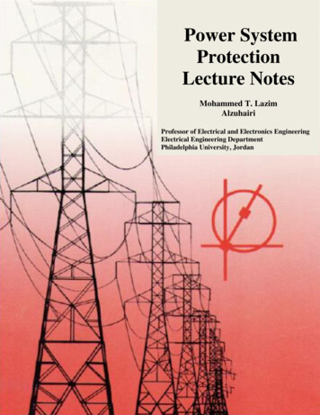
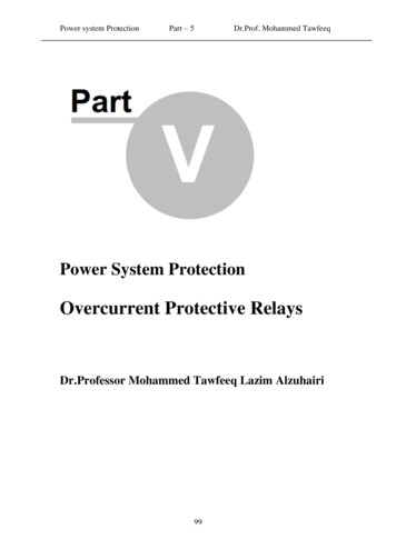
Power system ProtectionPart – 5Dr.Prof. Mohammed TawfeeqPower system protectionDr.Mohammed TawfeeqOvercurrent Protective RelaysOvercurrent relaysOvercurrent relaying is the simplest and cheapest type of protection usedfor protection of lines, transformers, generators and motor.Overcurrent relays TypesBased on operating time characteristics, normally defined by the time vs.current curve (or T-I curve), there are three main types of overcurrentrelays: Instantaneous Time-dependentDefinite time or Inversetime MixedDefinite time Inverse time1. Instantaneous Overcurrent Relays(50,50N)These relays operate without time delay, so they are called instantaneousunits(operating time 0.1 second). The simplest form of these relays isthe magnetic attraction types shown in Fig.1. Solid - State, digital andnumerical overcurrent relays also available.Fig.1011
Power system ProtectionPart – 5Dr.Prof. Mohammed Tawfeeq The pickup current (threshold) is adjustable and the user canchoose the setting from a relatively large range. Pickup Current Setting Taps in the Relay Current Coil Air-Gap Adjustment Spring Adjustment Features of Electromechanical 50 Elements Suitable for AC and DC Systems Operation Time Less Than 3 CyclesInstantaneous Curve (50)50 (ANSI)Only current is adjustable -Time tins 3 Cycles010
Part – 5Power system ProtectionDr.Prof. Mohammed Tawfeeq2. Time Overcurrent RelaysTime overcurrent relays operate with a time delay. The timedelay is adjustable. The minimum current at which the relayoperates (pick up current) is also adjustable.There are five different types of time over-current relays. Theirtime-current characteristic curves are: Definite time Inverse-time: Moderately inverse Inverse (Normal) Very inverse Extremely inverse2.1 Definite-Time Overcurrent RelaysThe definite-time relay operates with some delay. This delayis adjustable (as well as the current threshold).Definite - Time Curve (50)TimeAdjustabletsetInIset xInCurrentDefinite – Time Curve (50 ).011
Part – 5Power system ProtectionDr.Prof. Mohammed Tawfeeq2.2 Inverses-Time Overcurrent RelaysThis type of relay have an operating time depending on the value of thecurrent, generally with an inverse characteristic, the operation time of therelay is smaller as the current gets larger.These relays also have two settings: the pick-up current and the curvelevel. In early electromechanical relays the curve is set by means of adial. Thus, the setting is called the “time dial setting - TDS”.Inverse - Time Curve (51)Timet1AdjustabletinsIn10In2 InInverse time curve (51)011Current
Power system ProtectionPart – 5Dr.Prof. Mohammed TawfeeqDegrees of Inverse Curves The most common three types of curves used are,Normal inverse (NI), Very inverse (VI) and Extremelyinverse (EI).IEEE does not specify coefficients in the standard curve equation. Thus,each manufacturer’s curve is similar. But different IEC curves arestandardized011
Power system ProtectionPart – 5Dr.Prof. Mohammed TawfeeqTypical Inverse-Time Overcurrent Relay Elements1. Induction disc overcurrent relay.2. Shaded-Pole Induction 51 Element011
Power system ProtectionPart – 5Dr.Prof. Mohammed TawfeeqOvercurrent Relay Setting 50 Elements: Pickup Setting 51 Elements Pickup setting Time delay setting definite time: time setting inverse time: curve selectionSelecting an Overcurrent Relay Time CurveAccording to American StandrdTime-overcurrent relays (ANSI 51 relays) have two basicsettings:the pickup current and the time delay settings.The process for determining the time delay setting involves:(1) Calculation of a time delay value in definite-timeovercurrent elements(2) Selection in inverse-time overcurrent elements of a timecurrent curve from a family of curves.Note: Instantaneous over current (50) elements have only onesetting: the pickup current.011
Power system ProtectionPart – 5Dr.Prof. Mohammed Tawfeeq2.3 Mixed Curves Overcurrent RelaysMixed curves have all the advantages of the different types of overcurrentrelays. As the OC elements are built as separate units, we may implementthe overcurrent protection principles using: a combination of instantaneous and definite-time elements or a combination of instantaneous and inverse-time elements. a combination of instantaneous, definite-time and inverse-timeelements. a combination of definite-time and inverse-time elements(IDMT).2.3.1 Mixed Curves (Inverse-Time Instantaneous)Inverse time (TD)tInstantaneoustinsnInIn011I
Power system ProtectionPart – 5Dr.Prof. Mohammed Tawfeeq2.3.2 Mixed Curves (Inverse-Time Definite -Time Instantaneous)Inverse time (TD)tDefinite - TimeInstantaneoustinsnInInINote: This type of characteristic is mainly used in digitalrelays.1.3.3 Mixed Curves (Inverse-Time Definite -Time) IDMT –CharacteristicsThe most commonly used type of relay is the inverse definite withminimum time lag relay (IDMT) in which inverse characteristic plusdefinite time characteristic are used.In this relay, the operating time is approximately inversely proportional tothe fault current near pickup value and become substantially constantslightly above the pick up value of the relay. This characteristic is shownin the following figure.011
Power system ProtectionPart – 5Dr.Prof. Mohammed TawfeeqInverse time (TD)tDefinite - TimetinsInnInI This characteristic can be achieved using a core of electromagnetwhich gets saturated for currents slightly greater than the pickupcurrent. Wattmetric and shaded pole relays of induction type can be used toobtain this characteristic.019
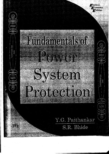
Power system ProtectionPart – 5Dr.Prof. Mohammed TawfeeqStandard Time and Inverse definite minimum time(IDMT) Relay Characteristics1. American Standard In American standard there are five different types of timeovercurrent relay. Their time-current characteristic curvesare: Definite minimum, CO-6 Moderately inverse, CO-7 Inverse, CO-8 Very inverse, CO-9 Extremely inverse, CO-11These time-current characteristics are compared in Figurebelow. The time lever settings are selected so that all relaysoperate in 0.2 sec at 20 times the tap setting.Typical time curves for CO-8 American overcurrent001
Power system ProtectionPart – 5Dr.Prof. Mohammed TawfeeqTypical time curves for CO-8 American overcurrentrelay (normal inverse).000
Power system ProtectionPart – 5Dr.Prof. Mohammed TawfeeqTypical time curves for CO-7 American overcurrentrelay (moderate inverse).001
Power system ProtectionPart – 5Dr.Prof. Mohammed Tawfeeq2. IEC and British StandardsIn IEC and BS Standards, we have three curves that one canuse:(a) The typical time curves for standard British Standard(BS142) and IEC Standard overcurrent relay (normalinverse). For: TMS 0.1- to -1.0. shown below:001
Power system ProtectionPart – 5Dr.Prof. Mohammed Tawfeeq(b) The typical time curves for standard BS and IECovercurrent relay(normal inverse).TMS 1.Figure- 1A(c ) OR the above figure can be given as:Figure – 1B001
Part – 5Power system ProtectionDr.Prof. Mohammed TawfeeqCurve Equations1. The typical time curves for CO-8 American overcurrentrelay(normal inverse) characteristics can be approximatedby the following equation.TD Time delayWhere2. The typical time curves for IEC and BS standardsovercurrent relay(normal inverse) characteristics can beapproximated by the following equation.trelay Where :0.14 TMSIF CTR PS TMS Time multiplier settingCTR Current transformer ratioPS Plug settingIF Fault primary current0010.02 1
Power system ProtectionPart – 5Dr.Prof. Mohammed TawfeeqNotes on IEC and BS Standards Meaning of the Plug Setting (PS) and Timemultiplier Setting (TMS) in Overcurrent Relays.The working principle of an inverse time overcurrent relay isdepicted in figure below. The current to be controlled feeds a coil with multiple tapswhich allow the pick up current setting - Plug setting (PS). The generated magnetic field makes the disc rotate with aspeed proportional to the current. A timing dial allows the adjustment between contacts andhence sets the operating time –Time dial setting. The braking magnet lessens the rotating speed and acts as anopposing force to the rotation. Varying the magnetization,different tripping curves can be achieved.Timingdial246 CurrentTapsorLaggingcoilBrakingPlugSettings(PS) 1001 2Inductiondisk
Power system ProtectionPart – 5Dr.Prof. Mohammed TawfeeqThe following Table gives the equivalent names for overcurrentrelay setting in both IEC and American StandardsIEC & BS standardAmerican StandardPlug Setting (PS)Current Tap Setting (CTS)Time Multiplier Setting (TMS)Time Dial Setting(TDS)Example: Calculate the plug setting and time multiplier setting for an IDMTL relayon the following network so that it will trip in 2.4 s (see Figure 1).The relaycharacteristic is shown in Figure2.The C.T. setting is 100/5 A and the fault current is1000 A.Figure 1Figure 2 (Figure – 1A given previously)001
Power system ProtectionPart – 5Dr.Prof. Mohammed TawfeeqAnswer:Fault current 1000 ACT ratio 100/5 AHence expected current into relay under fault conditions,Ir (1000 x 5/100) 50 AChoose plug setting of 5 A (100%). Therefore, current into relay as a multiple of plugsetting during fault: 50 / 5 10 We require the relay to operate after 2.4 s as soon as this much current startsflowing in the circuit. Referring to characteristic curves given in Figure 2above, read time multiplier setting where 10 times plug setting current and 2.4s cross, which is about 0.8. Accordingly, relay settings current plug tap 5 A(100%) and time multiplier 0.8. Alternatively, if the current plug setting is chosen as 125% (6.25 A), the faultcurrent through the relay will be 50/6.25 8 A. The graph shows that eighttimes plug setting to operate in 2.4 s, the time multiplier should be about 0.7.This technique is fine if the required setting falls exactly on the TM curve.However, if the desired setting falls between the curves, it is not easy toestimate the intermediate setting accurately as the scales of the graph arelog/log. The following procedure is therefore recommended (see Figure 3). Go to the multiple of plug setting current and read the second valuecorresponding to the 1.0 time multiplier curve. Then divide the desired timesetting by this figure. This will give the exact time multiplier setting: Second value at 10 times 3 ( at 8 times it is about 3.3s)Desired setting 2.4s.Figure 3(Figure – 1B previously)Logarithmic scale for I.D.M.T. relay001
Power system ProtectionPart – 5Dr.Prof. Mohammed TawfeeqExamples :Example1: Determine the PSM (plug setting multiplier) of a 5A, 2.2 sec overcurrent relay having a plug setting Ps 200%. The supply CT is rated 400:5Aand the fault current is 12000A.Solution:I p 12000 A5 150 A400On PS of 200%:200The relay current 5 10 A100150Hence PSM 1510I s 12000 Example 2: Determine the time of operation of an IDMTL relay rating 5A,2.2sec and having a plug setting PS 125% , and TMS 0.6. It is connected toa supply circuit through a C.T of 400/5 ratio. The fault current is 4000A.Solution:Since Ps 125% 1.25Then the operating current of the relay: 5 1.25 6.25AI p 4000 A5 50 A400sec ondary current50PSM 8relay.operating .current 6.25I s 4000 Now we can find the operating time of the relay in 3 methods:1) Directly from characteristics of the relay as shown in Fig. EX2-1(ifavailable)Fig. EX2-1The operating timeof the relay top fromfigure:top 1.9 (approx.)009
Power system ProtectionPart – 5Dr.Prof. Mohammed Tawfeeq2) From the curve of TMS 1(Fig. EX.2-2) , the operating time top for PSM 80.6is 3.3sec (TMS 1) and for TMS 0.6 is 1.92sec ( 3.3 .)1.0This comes from:TMS10.6? top3.3?0.6 3.3 . 1.92 sec1.0Fig. EX.2-23) Or from Fig. EX.2-3Fig. EX.2-3For PSM 8 , top 3.3 sec. for TMS 1. Now convert top to TMS 0.6 as above:TMS10.6? top3.3?0.6 3.3 . 1.92 sec1.0011
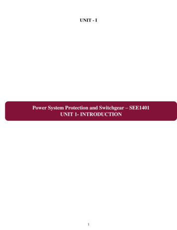
Power system ProtectionPart – 5Dr.Prof. Mohammed TawfeeqExample3: If the rated current (pick up current) of a relay is 3A, and the time dialsetting is 1. (a) How long does it take the relay to trip if the supply C.T is rated at400:5 A, and the fault current is 480A? The type of the OC relay is CO-8.(b) Solve using the standard curve equation and compare the results.Solution:(a) I p 480 A5 6A400Tap value of current 3AMultiple of tap value currentI6 s 2I tap 3From the CO-8 characteristic curves (see Figurebelow) :Operating time 2.1 sec.I s 480 (b) Using the curve equation: 5.95 t relay TD 2 0.18 M 1 TD 1 TDSIsI6M s 2I pickup I tap 3 5.95 t relay 1 2 0.18 (2) 1 2.16 sec(Same result)010
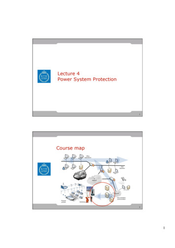
Part – 5Power system ProtectionDr.Prof. Mohammed TawfeeqExample4: For the relay R1 in the system shown determine the current tap settingCTS. If the maximum three-phase fault current is 2400A and the TDS 2.0 find theoperating time if the relay type is CO-8 (inverse type).Solution:I L1 Load current at the busbar1S 3V4.5 10 63 13.2 10 3 196.82 A5 3.28 A300Since the current tap setting (CTS) of CO-8 relay available are 4,5,6,7,8,10 and 12The relay current I R 196.82 Hence we choose CTS 4 Fault current I f 2400 ARelay current during fault 2400 As multiple of selected CTS 5 40 A30040 104From the CO-8 ch/s curve:Operating time 0.3105 sec011
IEEE does not specify coefficients in the standard curve equation. Thus, each manufacturer’s curve is similar. But different IEC curves are standardized . Power system Protection Part – 5 Dr.Prof. Mohammed Tawfee