Transcription
Power System ProtectionPart – 1Dr.Prof.Mohammed TawfeeqPower SystemProtectionLecture NotesMohammed T. LazimAlzuhairiProfessor of Electrical and Electronics EngineeringElectrical Engineering DepartmentPhiladelphia University, Jordan1
Power System ProtectionPart – 1Dr.Prof.Mohammed TawfeeqPower System protectionIntroduction Protection is the art or science of continuously monitoring thepower system, detecting the presence of a fault and initiating thecorrect tripping of the circuit breaker. The objectives of power system protection are to :— Limit the extent and duration of service interruptionwhenever equipment failure, human error, or adverse naturalevents occur on any portion of the system— Minimize damage to the system components involved inthe failure and Prevention of human injury Protection engineering concerned with the design and operationof "protection schemes". Protection schemes are specialized control systems that monitorthe power system, detecting faults or abnormal conditions andthen initiate correct action. In this course the power system is considered as all the plant andequipment necessary to generate, transmit, distribute and utilizethe electric power.2
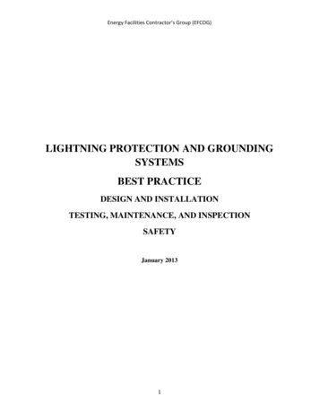
Power System ProtectionPart – 1Dr.Prof.Mohammed TawfeeqThe Construction of a Power system : Primary systemSecondary systems in a Power system Protection Auto control for voltage, frequency, reactive power compensation, power flow,network configuration and stability Metering for billing, operational control and statistical data Local manual control (plant status, voltage level reactive power support,network configuration) Remote manual control via communications links (SCADA) Plant condition monitoring and alarming (temperature,malfunction, maintenance need, operating duty) Communications infrastructure Instrument transformers - current and voltage transformers3
Power System ProtectionPart – 1Dr.Prof.Mohammed TawfeeqProtection against faults and abnormalitiesTypes of Faults and AbnormalitiesFaults :The principal electrical system faults are short circuits and overloads.Short circuits may be caused in many ways, including failure of insulationdue to excessive heat or moisture, mechanical damage to electricaldistribution equipment, and failure of utilization equipment as a result ofoverloading or other abuse.Short circuits may occur between two-phase conductors, between all phasesof a poly-phase system, or between one or more phase conductors andground. The short circuit may be solid (or bolted) or welded, in which casethe short circuit is permanent and has relatively low impedance. The maintypes of faults in a power system are: Short-circuit faults (3Ф, 2 Ф, Ф g, 2 Ф g) Open-circuit faults (open conductor) Complex faults (inter -circuit, broken conductor, cross -country etc) Inter-turn faults in windingsAbnormalities: Real power deficit - underfrequency Power swings Overload and excessive operating temperature Power frequency overvoltage or undervoltage Underexcitation of synchronous machines Overfluxing of power transformers Asynchronous operation of synchronous machines Overfrequency Mechanical defects i.e. leaking oil, tap changer mechanism faults .4
Power System ProtectionPart – 1Dr.Prof.Mohammed TawfeeqTypes of Faults Short circuit type faults (solidly earth fault)5
Power System ProtectionPart – 1Dr.Prof.Mohammed Tawfeeq Series (Open-circuit) type faults Faults in Windings6
Power System ProtectionPart – 1Dr.Prof.Mohammed TawfeeqTypical Short-Circuit Type Distribution Single-Phase-Ground: 70 – 80 %Phase-Phase-Ground: 17 – 10 %Phase-Phase: 10 – 8 %Three-Phase: 3 – 2 %Causes of Short-Circuit Faults Insulation breakdown due to inherent weakness Lightning Birds and animals bridging insulators Dig-ups for underground cables Poles collapsing Conductors breaking Vehicle impact Wind borne debris Incorrect operation by personnel Etc7
Power System ProtectionPart – 1Dr.Prof.Mohammed TawfeeqEffects of Short- Circuit Type Faults Large or very large currents can flow through parts of thenetwork - thousands or tens of thousands of Amps can beinvolved These large currents can only be allowed to flow for a veryshort time otherwise equipment and generators would bedamaged, most likely terminally - allowable short-circuitcurrent flow duration could range from as short as 10milliseconds up to say 3 seconds. Arcs, sparking and the heating effect of short-circuitcurrents can start fires involving non-electrical assets /property Very large mechanical forces can be caused by short circuit currents which have potential to break or damageequipment Electric current can "escape" from the network conductorsand flow through paths where they could create a hazard topeople or livestock and cause damage to non-electricalassets/property8
Power System ProtectionPart – 1Dr.Prof.Mohammed TawfeeqPerformance Requirements of Protection System Discriminate between load (normal) and fault(abnormal) conditions Not be confused by non-damaging transientconditions Be selective - coordinate with other protectionsystems Fast enough to prevent damage and hazards - butnot too fast Have no "blind spots" i.e. unprotected zones High degree of reliability and availability Secure against incorrect operation (security) Should not restrict rating of primary plant andequipment Should be affordable9
Power System ProtectionPart – 1Dr.Prof.Mohammed TawfeeqBasic Protection Scheme ComponentsThe isolation of faults and abnormalities requires the application ofprotective equipment that senses when an abnormal current flow exists andthen removes the affected portion from the system. The primary protectiveequipment components are shown in the following figure:PRCBEquipCTVTDC AuxHMIPCLTrProtection RelayCircuit BreakerProtected ItemCurrent TransformerVoltage TransformerDC Auxiliary supplyMan-machine interfaceCommunications LinkCB trip coilThe two primary protective equipment components used in the isolation offaults and abnormalities are circuit breakers, and protective relays.11
Power System ProtectionPart – 1Dr.Prof.Mohammed TawfeeqElements of a Protection System142.152A2.4F.A.D2.2 P2.331 – CT or VT,2- Relay3- TCF.A. Fault Alarm114- CB5- DC supply
Power System ProtectionPart – 1Dr.Prof.Mohammed TawfeeqElements of a Protection System1 The function of transducers (usually CT and VT) is toprovide current and voltage signals to the relays, todetect deviations of the parameters watched over.12.12 ARelays are the logicelements whichinitiate the trippingand closingoperations.2.4F.A.D2.2 P2.3312
Part – 1Power System ProtectionDr.Prof.Mohammed TawfeeqElements of a Protection System14 Circuit breakers2isolate the fault byinterrupting thecurrent.3 Tripping power, aswell as powerrequired by therelays, is usuallyprovided by thestation batterybecause is saferthan the ac faultedsystem.142.12AD52.4F.A.3132.2 P2.3
Part – 1Power System ProtectionDr.Prof.Mohammed TawfeeqPower System protectionDr. Mohamad TawfeeqProtective RelaysWhat is a Relay? Device which receives a signal from the power system anddetermines whether conditions are "normal" or "abnormal"(measuring function) If an abnormal condition is present, relay signals circuit breakerto disconnect equipment that could be damaged (Switching orsignaling function) "Relays" signal from system to circuit breaker.What is the Purpose of the Relay?The purpose of the protective relaying systems is to isolate only the faultycomponent of power system.Relaying equipments are classified into two groups:1. Primary relaying equipment.2. Back-up relaying equipment.Primary relaying is - the first line of defense for protecting the equipments.Back-up protection relaying works only when the primary relayingequipment fails (they are slow in action).14
Power System ProtectionPart – 1Dr.Prof.Mohammed TawfeeqFunctional Diagram of Relaying15
Power System ProtectionPart – 1Dr.Prof.Mohammed TawfeeqDesirable Relay Characteristics Speed (1/60 sec)* Minimizes damage from current* Maximizes power transfer during normal conditions,stability Security* Relay should not cause circuit breaker to open duringnormal conditions Dependability* Relay should cause circuit breaker to openduring abnormal conditions Sensitivity Ability of a relay to detect all faults for the expectedlimiting system and fault conditions Selectivity Ability of a relay system to discriminate betweenfaults internal and external to its intendedprotective zones.16
Power System ProtectionPart – 1Dr.Prof.Mohammed Tawfeeq17
Power System ProtectionPart – 1Dr.Prof.Mohammed TawfeeqPower System protectionDr. Mohamad TawfeeqClassifications of RelaysClassification of RelaysProtection relays can be classified in accordance with the function which theycarry out, their construction, the incoming signal and the type of protection.1. General . Construction: Electromagnetic. Solid state. Microprocessor. Computerized. Nonelectric (thermal, pressure .etc.).3. Incoming signal: Current. Voltage. Frequency. Temperature. Pressure. Velocity. Others.4. Type of protection Over current. Directional over current. Distance. Over voltage. Differential. Reverse power. Other.18
Power System ProtectionPart – 1Dr.Prof.Mohammed TawfeeqDefinitions: Normally open contact ( N/O): is one which is open when the relay is notenergized. Normally closed contact (N/C): is one which is closed when the relay is notenergized. Operating force or torque: that which tends to close the contacts of the relay. Restrain force or torque: that which opposes the operating force or torqueand tend to prevent the closure of the relay contacts. Pick-up level: the value of the actuating quantity (current or voltage), which ison the border above which the relay operates. Drop-out or reset level: the value of current or voltage below which a relayopens its contacts and comes to original position. Operating time: the time which elapses between the instant when theactuating quantity exceeds the pick-up value to the instant when the relaycontacts close. Reset time: the time which elapses between the instant when the actuatingquantity becomes less than the reset value to the instant when the relay contactreturns to its normal position. Primary relays: the relays which are connected directly in the circuit to beprotected. Secondary relays: the relays which are connected in the circuit to beprotected through CTs and V.Ts. Auxiliary relays: relays which operate in response to the opening or closing ofits operating circuit to assist another relay in the performance of its function. Thisrelay may be instantaneous or may have a time delay. Reach: a distance relay operates whenever the impedance seen by the relayis less than a prescribed value, this impedance or rt]ic corresponding distance isknownasthereachoftherelay. Instantaneous relay: One which has no intentional time-delay and operates inlessthan0.1second. Blocking: preventing the protective relay from tripping cither due to its owncharacteristics or to an additional relay. Time delay relay : One which is designed with a delaying means .19
Power System ProtectionPart – 1Dr.Prof.Mohammed TawfeeqPower System protectionTypes of RelaysDr. Mohamad TawfeeqThe main types of protective relays are summaries in the following diagram:Types of ngerTypeInductionCup21Shaded PoleNumericalRelays
Power System ProtectionPart – 1Dr.Prof.Mohammed TawfeeqPower System protectionDr. Mohamad TawfeeqElectromagnetic Relays1. Electromagnetic relaysElectromechanical Relays Research Began at the End of the 19thCentury The Relay Family Was Completed inthe 1930’s They Are Still in UseThese relays were the earliest forms of relay used for the protection of powersystems, and they date back nearly 100 years. They work on the principle ofa mechanical force causing operation of a relay contact in response to astimulus. The mechanical force is generated through current flow in one ormore windings on a magnetic core or cores, hence the termelectromechanical relay. The principle advantage of such relays is that theyprovide galvanic isolation between the inputs and outputs in a simple, cheapand reliable form – therefore for simple on/off switching functions where theoutput contacts have to carry substantial currents, they are still used.Electromechanical relays can be classified into several different types asfollows:a. magnetic attracted armature relaysb. magnetic induction relaysc. moving coild. thermalHowever, only attracted armature and induction types have significantapplication at this time, all other types having been superseded by moremodern equivalents. Electromagnetic relays are constructed withelectrical, magnetic and mechanical components, have an operating coiland various contacts and are very robust, inexpensive and reliable.However they required maintenance by skilled personnel.21
Power System ProtectionPart – 1Dr.Prof.Mohammed Tawfeeq1.1 . Magnetic attraction relaysMagnetic attraction relays can be supplied by AC or DC, and operate bythe movement of a piece of metal when it is attracted by the magneticfield produced by a coil. There are two main types of relay in this class. Attracted armature type (clapper type) Plunger type1.1.1 The attracted armature relays: which are shown in Fig.1,consists of a bar or plate of metal which pivots when it is attractedtowards the coil.(a)(b)(c)Fig. 1 Attracted armature-type relays22
Power System ProtectionPart – 1Dr.Prof.Mohammed Tawfeeq The armature is attracted to the electromagnet when the currentreaches a certain predetermined value (iop – operating current). Theforce of the armature will trip the link mechanism of the circuitbreaker, or it may operate as a relay and close the contacts of aseparate tripping circuit. The armature is attracted against gravity or aspring. By adjusting the distance of the armature from theelectromagnet, or the tension of the spring, the current at which thetrip operates can be varied to suit the circuit conditions. The armature carries the moving part of the contact, which isclosed or opened according to the design when the armature isattracted to the coil.1.1.2 Plunger type relay: The other type is the piston or solenoid relay,illustrated in Figure 2, in which α bar or piston is attracted axially within thefield of the solenoid. In this case, the piston also carries the operatingcontacts. This called plunger type relay.Figure 2Solenoid-type (plunger) relay It can be shown that the force of attraction is equal to K 1I2 - K2, whereΚ1 depends upon the number of turns on the operating solenoid, theair gap, the effective area and the reluctance of the magnetic circuit,among other factors. K2 is the restraining force, usually produced by aspring. When the relay is balanced, the resultant force is zero andtherefore Κ112 K2, so that :I K 2 / K1 constant.23
Power System ProtectionPart – 1Dr.Prof.Mohammed TawfeeqThis equation can be proved as follows:Atracted armature relay analysisIn general, the mechanical force produced by an electric magnet ispropotional to φ2; i.e:F (t ) 2Nmmf iwhereRRlgR l reluctance A g SoNiorlgHence F (t ) k 2 2N 2i 2l g2Where k is constantN 2i 2 k 2 k1i 2lgN2, k1 k l 2gThe net force isFn (t ) F (t ) k 2 k1i 2 k 2Wherek 2 restraining force produced by the springFn (t ) 0When the relay is balanced0 k1I 2 k2Sok1I 2 k2orI k2 constantk1I RMS value of i24
Power System ProtectionPart – 1Dr.Prof.Mohammed Tawfeeq In order to control the value at which the relay starts to operate, therestraining tension of the spring or the resistance of the solenoidcircuit can be varied, thus modifying the restricting force. Attractionrelays effectively have no time delay and, for that reason, are widelyused when instantaneous operations are required.Example :An electromagnetic relay of attracted armature type has constantsk1 0.6 and k 2 10 find whether the relay will operate or notwhen:(a) A current of 4A flows through the relay winding.(b)A current of 5A flows through the relay winding.(c)Find the minimum current required to operate the relay.Solution:(a)For 4A current:Fn (t ) k1 I 2 k 2 0.6(4) 2 10 0.4 NSo the relay will not operate. Since, the restrain force operating force.(b)For 5A current:Fn (t ) k1 I 2 k 2 0.6(5) 2 10 15 10 5NHence, the relay will operate, since, the operatingforce restrain force(c) The minimum current required to operate the relayis when the relay becomes at balanced condition, i.eFn (t ) 025
Part – 1Power System ProtectionorI k2 k1Dr.Prof.Mohammed Tawfeeq10 4.08 A0.61 .2 . M a g netic induction relaysAn induction relay works only with alternating current. Induction relays canbe grouped into three classes as set out below.1.2.1. Wattmetric-type relayIt consists of an electromagnetic system consists of two electromagnetsconstructed as shown in Fig.4, which operates on a moving conductor, in theform of a disc.Fig.4. Induction type overload relayElectromagnetic Induction Principle Induction type relay: General operating principle:The two magnets of the induction type relay produce two alternatingmagnetic fields 1 & 2 :26
Power System ProtectionPart – 1Dr.Prof.Mohammed Tawfeeq 1 1m sin t 2 2m sin( t )leads 1 by an angle .where 2 1 & 2 produce eddy currents in the rotating disc which are i φ1 and iφ2i 1 i 2 d 1dtd 2dtori 1 1m cos ti 2 2m cos( t )F1 is the force produced by intersection of 1 and i 2 .27
Power System ProtectionPart – 1Dr.Prof.Mohammed TawfeeqF2 is the force produced by intersection of 2 and i 1 .The net force isF F2 F1 [ 2 i 1 1i 2 ]ThusF 1m 2 m [sin( t ) cos t sin t cos( t )]Nowsin( t ) cos t sin t cos t cos sin cos 2 t sin t cos( t ) sin t cos t cos sin 2 t sin sin (cos 2 t sin 2 t ) sin HenceF 1m 2 m sin The net torque producedT Fr ForT K1 1m 2 m sin Let Φ1 is the R.M.S value of 1 , Φ2 is the R.M.S value of 2SoF 1 2 sin orT 1 2 sin In terms of currents:T I 1 I 2 sin orT K t I 1 I 2 sin 28
Power System ProtectionPart – 1Dr.Prof.Mohammed Tawfeeq Induction Type Relay with plug settingsFig.6 Induction type relay withPlug settings1.2.2. Induction-Cup relayThe operation is similar to the induction disc; here, two fluxes at right anglesinduce eddy currents in a bell-shaped cup which rotates and carries themoving contacts. A four-pole relay is shown in Figure 7.Fig 7.Four-pole induction-cup relay.29
Power System ProtectionPart – 1Dr.Prof.Mohammed Tawfeeq1.2.3. Shaded-pole relayIn this case operation of the electromagnetic section is short-circuited bymeans of a copper ring or coil. This creates a flux in the area influencedby the short circuited section (the so-called shaded section) which lags theflux in the nonshaded section, see Figure 8.Fig.8 Shaded – pole Relay Note that the main coils has TAPS, this means that thenumber of turns is actually adjustable.In the electromagnetic induction principle, the relay element has a nonmagnetic rotor (an aluminum or copper disc or cylinder) in which coilscreate magnetic fluxes that induce circulating currents. The interactionbetween the fluxes and the circulating currents generates torque. This is theoperation principle of induction motors.If the current is sinusoidal and the iron core is assumed to have a linearbehavior, the magnetic field and the magnetic flux in the iron core aresinusoidal too. Note that the flux is divided in two parts. One flows throughthe normal (‘pole”) and the other flows through the shaded pole. These twofluxes are similar in magnitude but different in angle.Features of the Induction Principle Suitable for AC Systems The Torque Does Not Vary With Time: No Vibration Inherent Rejection of DC Offset: Low Overreach31
Power System ProtectionPart – 1Dr.Prof.Mohammed TawfeeqPower System protectionDr. Mohamad TawfeeqSolid State Relays2. Solid State Relays ResearchBegan in the 1940’s First Commercial Products in the Late1950’s Full Development in the 1960’s Advantages Over ElectromechanicalRelaysA solid state relay (SSR) is a solid state electronic component that providesa similar function to an electromechanical relay but does not have anymoving components, increasing long-term reliability. Introduction of staticrelays began in the early 1960’s. Their design is based on the use ofanalogue electronic devices instead of coils and magnets to create the relaycharacteristic. Early versions used discrete devices such as transistors anddiodes in conjunction with resistors, capacitors, inductors, etc., but advancesin electronics enabled the use of linear and digital integrated circuits in laterversions for signal processing and implementation of logic functions. Figure9 shows a small overcurrent relay and the circuit board for a simple staticrelay.Fig.9 . Small overcurrent relay and the circuit board for a simple static relay.31
Power System ProtectionPart – 1Dr.Prof.Mohammed TawfeeqSolid State Relay Principle of OperationSolid state relays (static relays) are extremely fast in their operation. Theyhave no moving parts and have very quick response time and they are veryreliable.Figure 1 shows the elements used in a single – phase time lag overcurrentrelay.RRelayCTRectifierCFig.1 The AC input from the current transformer CT is rectified andconverted to DC voltage Vin through shunt resistance. A delay time circuit (RC) is used to produce the required time delay. If Vin VR, the base – emitter of transistor TR1 is reversed biasforcing the transistor to be in the cut off state. When Vin VR, transistor TR1 will be in the ON state and in turn willturn on TR2 and the output relay is activated. VR is set by R1 and R2.32
Power System ProtectionPart – 1Dr.Prof.Mohammed TawfeeqPower System protectionDr. Mohamad TawfeeqComputerized Relays3. Computerized Relay3.1. Digital relays Research Began in the 1960’s Basic Developments: Early 1970’s A Technical and Economic Solution:the Microprocessor Commercial Relays: Early 1980A digital protective relay is a microcomputer controlled relay. The dataacquisition system collects the transducers information and converts it to theproper form for use by the microcomputer. Information from CT and PT andother systems is amplified and sampled at several kHz. The sampled signalsare digitized with A/D converter and fed to registers in microprocessorsystem. The microprocessor may use some kind of counting technique, oruse the Discrete Fourier Transform (DFT) to compare the information withpreset limits for overcurrent , over/under voltage etc, and then sendcommand through D/A converter to alarm or trip signals to the circuitbreakers.33
Power System ProtectionPart – 1Dr.Prof.Mohammed TawfeeqOperation : The relay applies A/D (analog/digital) conversion processes to theincoming the voltages and currents.The relay analyzes the A/D converter output to extract the magnitudeof the incoming quantity (RMS value) using Fourier transformconcept. Further, the Fourier transform is commonly used to extractthe signal's phase angle relative to some reference.The digital relay is capable of analyzing whether the relay should tripor restrain from tripping based on current and/or voltage magnitude(and angle in some applications).Examples of digital relays are shown in Figure 10.Fig.10 Digital relaysSignal Path for Microprocessor RelaysThe signal path for voltage and current input signals are shown in Fig.11.Fig.1134
Power System ProtectionPart – 1Dr.Prof.Mohammed Tawfeeq After the currents and voltages are reduced to acceptable levels by theinstrument transformers, the signals are filtered with an analog filter The signal then digitized and re-filtered with a digital filter. Numerical operating quantities are then calculated from the processedwaveforms.Digital Relay Construction Analog Input Subsystem Discrete Input SubsystemA/D Converter Microprocessor Discrete output Subsystem Operating signaling and communication subsystemsFig.1235
Power System ProtectionPart – 1Dr.Prof.Mohammed TawfeeqDiscrete Input Subsystem Surge Suppression Signal Conditioning! 36
Power System ProtectionPart – 1Dr.Prof.Mohammed TawfeeqSampling frequency is the inverse of sampling rate.37
Power System ProtectionPart – 1Dr.Prof.Mohammed TawfeeqThe digital filter smoothes the signal by eliminating DC and frequenciescomponents those are different than the fundamental (when required).38
Power System ProtectionPart – 1Dr.Prof.Mohammed Tawfeeq39
Power System ProtectionPart – 1Dr.Prof.Mohammed TawfeeqThese routines implement the protection function:overcurrent, directional, distance,differential, etc.Other Features : The relay has some form of advanced event recording. The eventrecording would include some means for the user to see the timing ofkey logic decisions, relay I/O (input/output) changes, and see in anoscillographic fashion at least the fundamental frequency componentof the incoming AC waveform.The relay has an extensive collection of settings, beyond what can beentered via front panel knobs and dials, and these settings aretransferred to the relay via an interface with a PC (personal computer),and this same PC interface is used to collect event reports from therelay.The more modern versions of the digital relay will contain advancedmetering and communication protocol ports, allowing the relay tobecome a focal point in a SCADA system.41
Power System ProtectionPart – 1Dr.Prof.Mohammed TawfeeqAdvantages of Digital Relays Low Cost Multifunctionality Protection and control Measurement Fault recording Communications capability Compatibility with Digital Integrated Systems High Reliability Relays (integration, self-testing) Protection system (supervised by the relays) Sensitivity and Selectivity New Protection Principles New Relay Operating Characteristics Maintenance-Free Reduced Burden on CTs and VTs Adaptive Protection41
Power System ProtectionPart – 1Dr.Prof.Mohammed TawfeeqPower System protectionDr. Mohamad TawfeeqNumerical Relays3.2. NUMERICAL RELAYSThe distinction between digital and numerical relay rests on points of finetechnical detail, and is rarely found in areas other than Protection. They canbe viewed as natural developments of digital relays as a result of advances intechnology. Typically, they use a specialized digital signal processor (DSP)as the computational hardware, together with the associated software tools.Numerical measurement treatmentI1UDnumerically the measurement1value is converted into a000101001001Asetting value storedin EEPROM000101001011meas. current 1,05 Asetting value 1,10 Ameas. current 1,15 Asetting value 1,10 Alogical digit and thencompared with another digitstored in a memoryno pick-uppick-up42
Part – 1Power System ProtectionDr.Prof.Mohammed TawfeeqMode of operationAnalog InputsAnalog-Digital-ConversionyesFault detectionProtection programnoRoutine programCommand and information outputAdvantages of numerical technology Comprehensive information supply clear representation of the fault sequenceFault sequence of event and disturbance recording indicate What actually happened ? What did the current and voltage signals look like (CTsaturation) ? When did the protection issue a trip signal ? How long did the circuit breaker need to operate ? What was the magnitude of the interrupted current ? How did the system behave after the circuit breakertripped ?43
Power System ProtectionPart – 1Dr.Prof.Mohammed TawfeeqElectromagnetic vs Computerized44
Power System ProtectionPart – 1Dr.Prof.Mohammed TawfeeqANSI Device NumbersThe ANSI Standard Device Numbers denote what features a protective device supports(such as a relay or circuit breaker). These types of devices protect electrical systems andcomponents from damage when an unwanted event occurs, such as a electrical fault.List of Device Numbers 1 - Master Element2 - Time Delay Starting or Closing Relay3 - Checking or Interlocking Relay4 - Master Contactor5 - Stopping Device6 - Starting Circuit Breaker7 - Anode Circuit Breaker8 - Control Power Disconnecting Device9 - Reversing Device10 - Unit Sequence Switch12 - Overspeed Device13 - Synchronous-speed Device14 - Underspeed Device15 - Speed - or Frequency-Matching Device20 - Elect. operated valve (solenoid valve)21 - Distance Relay23 - Temperature Control Device25 - Synchronizing or Synchronism-Check Device26 - Apparatus Thermal Device27 - Undervoltage Relay29 - Isolating Contactor30 - Annunciator Relay32 - Directional Power Relay36 - Polarity or Polarizing Voltage Devices37 - Undercurrent or Underpower Relay38 - Bearing Protective Device39 - Mechanical Conduction Monitor40 - Field Relay41 - Field Circuit Breaker42 - Running Circuit Breaker43 - Manual Transfer or Selector Device46 - Reverse-phase or Phase-Balance Relay47 - Phase-Sequence Voltage Relay48 - Incomplete-Sequence Relay49 - Machine or Transformer Thermal Relay50 - Instantaneous Overcurrent51 - AC Time Overcurrent Relay45
Power System Protection Part – 1Dr.Prof.Mohammed Tawfeeq52 - AC Circuit Breaker53 - Exciter or DC Generator Relay54 - High-Speed DC Circuit Breaker55 - Power Factor Relay56 - Field Application Relay59 - Overvoltage Relay60 - Voltage or Current Balance Relay61 - Machine Split Phase Current Balance62 - Time-Delay Stopping or Opening Relay63 - Pressure Switch64 - Ground Detector Relay65 - Governor66 - Starts per Hour67 - AC Directional Overcurrent Relay68 - Blocking Relay69 - Permissive Control Device71 - Level Switch72 - DC
Power System Protection Part - 1 Dr.Prof.Mohammed Tawfeeq 3 The Construction of a Power system : Primary system Secondary systems in a Power system Protection Auto control for voltage, frequency, reactive power compensation, power flow, network configuration and stability