Transcription
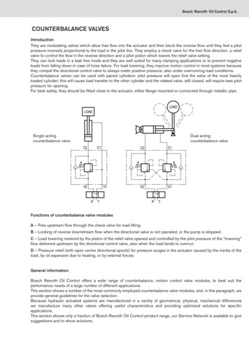
Bosch Rexroth Oil Control S.p.A.COUNTERBALANCE VALVESIntroductionThey are modulating valves which allow free flow into the actuator and then block the reverse flow until they feel a pilotpressure inversely proportional to the load in the pilot line. They employ a check valve for the free flow direction, a reliefvalve to control the flow in the reverse direction and a pilot piston which lowers the relief valve setting.They can lock loads in a leak free mode and they are well suited for many clamping applications or to prevent negativeloads from falling down in case of hose failure. For load lowering, they improve motion control in most systems becausethey compel the directional control valve to always meter positive pressure, also under overrunning load conditions.Counterbalance valves can be used with paired cylinders: pilot pressure will open first the valve of the most heavilyloaded cylinder; this will cause load transfer to the other cylinder and the related valve, still closed, will require less pilotpressure for opening.For best safety, they should be fitted close to the actuator, either flange mounted or connected through metallic pipe.Single actingcounterbalance valveDual actingcounterbalance valveFunctions of counterbalance valve modulesA – Free upstream flow through the check valve for load lifting.B – Locking of reverse downstream flow when the directional valve is not operated, or the pump is stopped.C – Load lowering metered by the piston of the relief valve opened and controlled by the pilot pressure of the “lowering”flow delivered upstream by the directional control valve, also when the load tends to overrun.D – Pressure relief (with open centre directional spools) for pressure surges in the actuator caused by the inertia of theload, by oil expansion due to heating, or by external forces.General informationBosch Rexroth Oil Control offers a wide range of counterbalance, motion control valve modules, to best suit theperformance needs of a large number of different applications.This section shows a number of the most commonly employed counterbalance valve modules, and, in this paragraph, weprovide general guidelines for the valve selection.Because hydraulic actuated systems are manufactured in a variety of geometrical, physical, mechanical differenceswe manufacture many other valves offering useful characteristics and providing optimized solutions for specificapplications.This section shows only a fraction of Bosch Rexroth Oil Control product range, our Service Network is available to givesuggestions and to show solutions.
Bosch Rexroth Oil Control S.p.A.Pressure setting of the relief functionThe relief section of the valve must have a pressure setting (Pt) high enough in order to be capable to fully re-close thepiston in a leak free condition and stop any downstream flow also under maximum load induced pressure (Pmax).For this purpose the pressure setting (Pt) must be at least 30% higher than P max, and this is expressed by the followingbasic formula, which can be seen also in each catalogue page:Pt (1.3 x Pmax)Pilot pressure required to open the valveLoad lowering is prevented by the relief section of the counterbalance valve and the load induced pressure (Pload)generates a force in the opening direction opposite to the spring load, consequently the load diminishes the actual pilotpressure needed to start opening the relief piston.In case of counterbalance valve fitted to a double acting cylinder and in the ideal situation of no back-pressure in the oilreturn line (V2 – T line) and absence of seal friction, the pilot pressure needed to start opening the valve, Ppil or crackingpressure, can be determined by the following basic formulas where φ is the cylinder ratio and R the pilot ratio of thevalve.φ cylinder bore area / cylinder annular areaR area of pilot piston / differential area of control piston1) In case of load pushing on the cylinder rod and valve fitted to the full bore side.Ppil Pt - Pload1R φoften simplified as Ppil Pt - PloadR2) In case of load pulling the cylinder rod and valve fitted to the annular chamberPpil Pt - PloadR φ3) In case of counterbalance valve fitted to an equal area actuator or to an hydraulic motor where φ 1, the crackingpressure can be determined as following:Ppil Pt - PloadR 1
Bosch Rexroth Oil Control S.p.A.Different pilot ratios are available and, as a general indication, it can be stated that:High pilot ratio (R 8 : 1): allows load lowering with reduced pilot pressure for a faster machine operation and withenergy saving. It is best suited for applications where the geometry of the structure maintains the load induced pressuresapproximately constant during motion (example: extension of a straight boom).Low pilot ratio (R 4 : 1): requires a higher pilot pressure for load lowering but it permits a more precise and smoothcontrol of the motion. It is recommended for applications where the geometry of the structure determines high changes ofthe load induced pressure during motion with resulting instability of the machine (example: cylinder controlling a pivotingarm).Important:For best operation, avoid back-pressure at the V2 port into which the relief spring is usually vented; back-pressure hastwo negative effects:a) it pushes the relief piston in the closed direction, and it increases the pressure needed to open the relief section.b) it opposes the pilot piston and increases the pilot pressure needed to open the valve and to lower the load.When necessary, the above mentioned effects can be partially or totally neutralized by employing Bosch Rexroth OilControl special counterbalance valves relief compensated to back-pressure (CC type) or fully compensated to backpressure (CCAP type).Relief compensated type counterbalance valves or CC typeThese valve modules have a special configuration of the relief piston that allows the relief opening independently from anyback pressure whereas the piloted opening remains subject to additive pressure at port V2.They are employed when it is necessary to relief pressure at thepre-established pressure setting (Pt), without over-pressurizing thesystem, independently from any back-pressure in the return line.They are normally fitted in conjunction with main control valveshaving closed centre spools equipped with port relief valves.Single acting counterbalancevalve “CC” type
Bosch Rexroth Oil Control S.p.A.Vented type counterbalance valves or CCAP typeThese valve modules have a fully vented spring chamber and boththe relief opening and the piloted opening are independent fromback-pressure at port V2. Venting is often open to atmosphere and,whenever possible, is connected to tank or to a low pressure line.They must be used only in conjunction with main control valveshaving closed centre spools and equipped with port relief valves.Single acting counterbalancevalve “CCAP” typeThis type of “fully balanced” valves is necessary in a few typical applications and exactly:a) When the piloted opening determines a reverse flow toward a highly pressurized line (example: regenerative circuitsfor cylinders, where the oil from the annular chamber is recycled into the line feeding the full bore side, or series typecircuits, where the oil unloaded by an actuator is employed to power a second actuator).b) When pressure surging in the oil return line could cause oscillations of the relief piston which would amplify flowinstability and fluctuations.c) When the pilot opening is controlled through a joystick which delivers a “low pressure signal” and the relief pistonneeds to maintain stable open positions also with strong pressure fluctuations.d) When the counterbalance valve is part of a closed loop circuit with pressure upstream and downstream.Classification of counterbalance valve modulesThe Bosch Rexroth Oil Control pilot assisted counterbalance valve modules «VBSO» are available in different designconfigurations and different sizes, each suitable for certain applications; they can be single acting «VBSO-SE», ordouble acting «VBSO-DE» and they can be grouped into the following two main families.A - Pilot assisted counterbalance valves with coaxial annular check valve and with pilot piston integral with relief plunger.
Bosch Rexroth Oil Control S.p.A.Very compact design providing excellent flow control, good tolerance to oil contamination; internal components developedespecially for parts in body (most frequently steel body), but occasionally available also as complete “screw-in cartridges”,with various flow capacities ranging from 40 l/min up to 350 l/min.The geometry of these valves in their standard configuration makes them particularly sensitive to back-pressure.Both the actual relief setting and the pilot pressure are affected, as expressed by the following formulas.Pr Pt Pv (R 1)Where:Pr Pt Pv R Pp Ppil Pp Ppil PvR 1RActual pressure for relief openingRelief pressure setting in absence of back-pressure at V2 portBack-pressure at V2 portPilot ratioActual pilot pressure needed for piloted openingPilot pressure needed for piloted opening, in absence of back-pressure at V2 portB - Pilot assisted counterbalance valves with separate check valve and separate pilot pistonThe traditional design, often with parts in aluminium body (steel versions available in many cases), high flow capacity andcompact dimensions, available in different sizes.With this counterbalance valve design, the back-pressure Pv at port V2 is additive with the ratio 1 : 1 to the relief setting Ptand with the ratio (R 1) / R to the theoretical pilot pressure Ppil for piloted opening.Pr (Pt Pv)Pp Ppil PvR 1R
Bosch Rexroth Oil Control S.p.A.Dampening of the pilot piston, for stable pilot opening and smooth load loweringThe operation of a counterbalance valve while controlling load lowering is affected by many variables among which the inputof the operator, the opening areas of the directional valve, the load induced pressure, the viscosity of the fluid, etc., and,most of all, the fluctuations of the pilot signal.Insufficient dampening of counterbalance valves is often the cause for undesired oscillations; Bosch Rexroth Oil Controlhas developed counterbalance valve modules with a variety of special devices in order to achieve a more controllable andstable pilot function for better load lowering.Here are the most commonly used.AFixed restrictionBOne way fixed restrictionCOne way adjustable restrictionThis is generally achieved with a special shaped screw is fitted in the pilot line between the pilot port and the pilot pistonof the valve. The pilot flow enters along the long, narrow helical space formed between the damper screw and the femalethread in the valve body. The restriction level can be adjusted by varying the number of threads, or the length of the screwwhich enters the female thread. The pilot oil enters as a smooth steady laminar flow which moves the piston, and maintainsthe signal very stable. A check valve is often incorporated inside the screw so that, when pressure drops in the system, thepilot pressure is released quickly and the valve blocks immediately, that is a safety must.DReduced pilot pressure “PRPF”Pilot flow enters through an orifice and is partially drained to tank through a second orifice; by selecting the dimensions ofthe two orifices, the pilot pressure reduction can be calibrated.The combined effect of the inlet restriction and the restriction to tank enables to maintain the signal very stable also incombination with load sensing main control valve.
Bosch Rexroth Oil Control S.p.A.The above arrangements are very effective for pilot dampening but are sensitive to viscosity; changes in oil temperature canproduce variations in response time, independent from the operator’s input.The target of the latest developments has been to design dampening devices which combine both sufficient dampeninggood responsiveness.To overcome the delay problem, a small normally open by-pass (VEM) has been added in parallel with the damper screw.The VEM closes and quickly locks any further flow inlet when the pressure setting is reached (see scheme).When the lowering is started slowly by the operator, the pilot oil enters immediately the pilot chamber and pressurizes it upto almost cracking point; only the final pressurization is achieved through the dampening screw, and this happens quicklywithout delay.EDampening with normally open by-pass(European patent pending)In case of quick lowering, the VEM locks almost immediately and the pressure increase in the pilot chamber is controlledby the dampening screw.When a quick closing of the counterbalance valve must be achieved, the pilot oil can be discharged through the VEM itselfwhich operates as a check valve in the reverse direction.The valve modules included in this catalogue are only a fraction of Bosch Rexroth Oil Control complete product range formobile applications and represents the most common standard solutions.Bosch Rexroth Oil Control comprehensive experience particularly in mobile hydraulics has allowed to develop a variety ofsolutions and the “parts in body” concept gives many options because it allows easy addition of components.In most cases special pilot devices are the result of joint development between our Service Network and the Customer’s.
Counterbalance valves can be used with paired cylinders: pilot pressure will open first the valve of the most heavily loaded cylinder; this will cause load transfer to the other cylinder and the related valve, st