Transcription
Dell EMC PowerVault ME4 Series StorageSystemDeployment GuideJuly 2021Rev. A07
Notes, cautions, and warningsNOTE: A NOTE indicates important information that helps you make better use of your product.CAUTION: A CAUTION indicates either potential damage to hardware or loss of data and tells you how to avoidthe problem.WARNING: A WARNING indicates a potential for property damage, personal injury, or death. 2018 – 2021 Dell Inc. or its subsidiaries. All rights reserved. Dell, EMC, and other trademarks are trademarks of Dell Inc. or its subsidiaries.Other trademarks may be trademarks of their respective owners.
ContentsChapter 1: Before you begin. 6Unpack the enclosure. 6Safety guidelines. 7Safe handling.7Safe operation. 8Electrical safety.8Rack system safety precautions. 9Installation checklist.9Planning for installation. 10Preparing for installation. 10Preparing the site and host server. 11Required tools. 11Requirements for rackmount installation. 11Disk drive module.11Drive carrier module in 2U chassis.11Drive status indicators. 12Blank drive carrier modules.13DDIC in a 5U enclosure. 13Populating drawers with DDICs. 14Chapter 2: Mount the enclosures in the rack.15Rackmount rail kit. 15Install the 2U enclosure. 15Install the 2U enclosure front bezel.16Install the 5U84 enclosure. 16Connect optional expansion enclosures. 18Cable requirements for expansion enclosures.18Chapter 3: Connect to the management network. 21Chapter 4: Cable host servers to the storage system.22Cabling considerations. 22Connecting the enclosure to hosts.22CNC technology.22Fibre Channel protocol. 23iSCSI protocol.23SAS protocol.25Host connection. 2516 Gb Fibre Channel host connection.2510 GbE iSCSI host connection.2510Gbase-T host connection. 2512 Gb HD mini-SAS host connection. 26Connecting direct attach configurations.26Single-controller module configurations. 26Contents3
Dual-controller module configurations. 26Chapter 5: Connect power cables and power on the storage system.30Power cable connection. 30Chapter 6: Perform system and storage setup.33Record storage system information.33Using guided setup.33Web browser requirements and setup. 33Access the PowerVault Manager. 33Update firmware. 34Use guided setup in the PowerVault Manager Welcome panel. 34Chapter 7: Perform host setup. 43Host system requirements. 43About multipath configuration.43Windows hosts.43Configuring a Windows host with FC HBAs. 43Configuring a Windows host with iSCSI network adapters. 45Configuring a Windows host with SAS HBAs. 48Linux hosts.50Configuring a Linux host with FC HBAs . 50Configure a Linux host with iSCSI network adapters.52SAS host server configuration for Linux. 55VMware ESXi hosts. 57Fibre Channel host server configuration for VMware ESXi. 57iSCSI host server configuration for VMware ESXi.58SAS host server configuration for VMware ESXi.62Citrix XenServer hosts. 64Fibre Channel host server configuration for Citrix XenServer. 64iSCSI host server configuration for Citrix XenServer. 66SAS host server configuration for Citrix XenServer.69Chapter 8: Troubleshooting and problem solving.71Locate the service tag. 71Operators (Ops) panel LEDs. 712U enclosure Ops panel. 715U enclosure Ops panel. 72Initial start-up problems. 742U enclosure LEDs. 755U enclosure LEDs. 77Module LEDs.80Troubleshooting 2U enclosures. 81Troubleshooting 5U enclosures.82Fault isolation methodology. 83Options available for performing basic steps. 83Performing basic steps. 84If the enclosure does not initialize.85Correcting enclosure IDs. 854Contents
Host I/O.86Dealing with hardware faults. 86Appendix A: Cabling for replication. 90Connecting two storage systems to replicate volumes.90Host ports and replication.91Example cabling for replication.91Single-controller module configuration for replication.91Dual-controller module configuration for replication. 92Isolating replication faults.94Diagnostic steps for replication setup.95Appendix B: SFP transceiver for FC/iSCSI ports. 98Appendix C: System Information Worksheet. 100Appendix D: Setting network port IP addresses using the CLI port and serial cable. 103Mini-USB Device Connection. 106Microsoft Windows drivers. 106Linux drivers. 107Contents5
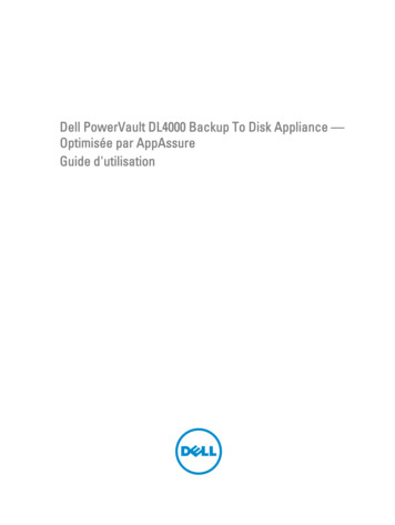
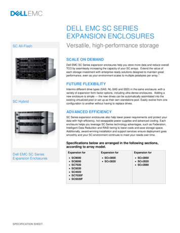
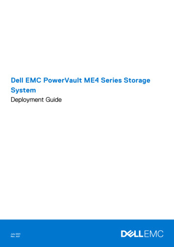
1Before you beginThis document describes the initial hardware setup for Dell EMC PowerVault ME4 Series storage systems.This document might contain third-party content that is not under the control of Dell EMC. The language in the third-partycontent might be in inconsistent with the current guidelines for Dell EMC content. Dell EMC reserves the right to update thisdocument after the content is updated by the relevant third parties.Topics: Unpack the enclosureSafety guidelinesInstallation checklistPlanning for installationPreparing for installationDisk drive modulePopulating drawers with DDICsUnpack the enclosureExamine the packaging for crushes, cuts, water damage, or any other evidence of mishandling during transit. If you suspectthat damage has happened, photograph the package before opening, for possible future reference. Retain the original packagingmaterials for use with returns. Unpack the 2U storage system and identify the items in your shipment.NOTE: The cables that are used with the enclosure are not shown in Unpacking the 2U12 and 2U24 enclosures on page6. The rail kit and accessories box is located below the 2U enclosure shipping box lid.Figure 1. Unpacking the 2U12 and 2U24 enclosures1. Storage system enclosure3. Rackmount right rail (2U)5. Enclosure front-panel bezel option2. Rackmount left rail (2U)4. Documentation6. Rack mount ears 2U enclosures are shipped with the controller modules or input/output modules (IOMs) installed. Blank drive carriermodules must be installed in the unused drive slots. For enclosures configured with CNC controller modules, locate the SFP transceivers included with the shipment. SeeSFP transceiver for FC/iSCSI ports on page 98. Unpack the 5U84 storage system and identify the items in your shipment.NOTE: The cables that are used with the enclosure are not shown in Unpacking the 5U84 enclosure on page 7. Therail kit and accessories box is located below the 5U84 enclosure shipping box lid.6Before you begin
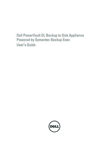
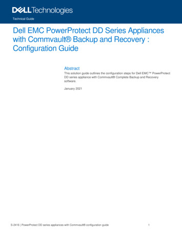
Figure 2. Unpacking the 5U84 enclosure1. Storage system enclosure3. Documentation5. Rackmount right rail (5U84)2. DDICs (Disk Drive in Carriers)4. Rackmount left rail (5U84)6. Drawers DDICs ship in a separate container and must be installed into the enclosure drawers during product installation. Forrackmount installations, DDICs are installed after the enclosure is mounted in the rack. See Populating drawers withDDICs on page 14. For enclosures configured with CNC controller modules, locate the SFP transceivers included with the shipment. SeeSFP transceiver for FC/iSCSI ports on page 98.CAUTION: A 5U enclosure does not ship with DDICs installed, but the rear panel controller modules or IOMsare installed. This partially populated enclosure weights approximately 64 kg (142 lb). You need a minimum oftwo people to remove the enclosure from the box.Safety guidelinesAlways follow these safety guidelines to avoid injury and damage to ME4 Series components.If you use this equipment in a manner that is not specified by Dell EMC, the protection that is provided by the equipment couldbe impaired. For your safety and precaution, observe the rules that are described in the following sections:NOTE: See the Dell EMC PowerVault ME4 Series Storage System Getting Started Guide for product safety and regulatoryinformation. Warranty information is included as a separate document.Safe handlingDell EMC recommends that only individuals with rack-mounting experience install an enclosure into a rack.CAUTION: Use this equipment in a manner specified by Dell EMC. Failure to do so may cancel the protectionthat is provided by the equipment. Unplug the enclosure before you move it or if you think that it has become damaged in any way. A safe lifting height is 20U. Always remove the power cooling modules (PCMs) to minimize weight before you move the enclosure. Do not lift the enclosures by the handles on the PCMs—they are not designed to take the weight.CAUTION: Do not try to lift the enclosure by yourself: Fully configured 2U12 enclosures can weigh up to 32 kg (71 lb) Fully configured 2U24 enclosures can weigh up to 30 kg (66 lb)Before you begin7
Fully configured 5U84 enclosures can weigh up to 135 kg (298 lb). An unpopulated enclosure weighs 46 kg(101 lb). Use a minimum of two people to lift the 5U84 enclosure from the shipping box and install it in the rack.Before lifting the enclosure: Avoid lifting the enclosure using the handles on any of the CRUs because they are not designed to take theweight. Do not lift the enclosure higher than 20U. Use mechanical assistance to lift above this height. Observe the lifting hazard label affixed to the storage enclosure.Safe operationOperation of the enclosure with modules missing disrupts the airflow and prevents the enclosure from receiving sufficientcooling.NOTE: For a 2U enclosure, all IOM and PCM slots must be populated. In addition, empty drive slots (bays) in 2U enclosuresmust hold blank drive carrier modules. For a 5U enclosure, all controller module, IOM, FCM, and PSU slots must bepopulated. Follow the instructions in the module bay caution label affixed to the module being replaced. Replace a defective PCM with a fully operational PCM within 24 hours. Do not remove a defective PCM unless you havea replacement model of the correct type ready for insertion. Before removal/replacement of a PCM or PSU, disconnect supply power from the module to be replaced. See the DellEMC PowerVault ME4 Series Storage System Owner’s Manual. Follow the instructions in the hazardous voltage warning label affixed to power cooling modules.CAUTION: 5U84 enclosures only To prevent a rack from tipping over, drawer interlocks stop users from opening both drawers simultaneously.Do not attempt to force open a drawer when the other drawer in the enclosure is already open. In a rackcontaining more than one 5U84 enclosure, do not open more than one drawer per rack at a time. Observe the hot surface label that is affixed to the drawer. Operating temperatures inside enclosure drawerscan reach 60 C (140 F) . Take care when opening drawers and removing DDICs. Due to product acoustics, ear protection should be worn during prolonged exposure to the product inoperation. Observe the drawer caution label. Do not use open drawers to support any other objects or equipment.Electrical safety The 2U enclosure must be operated from a power supply input voltage range of 100–240 VAC, 50/60Hz.The 5U enclosure must be operated from a power supply input voltage range of 200–240 VAC, 50/60Hz.Provide a power source with electrical overload protection to meet the requirements in the technical specification.The power cord must have a safe electrical grounding connection. Check the grounding connection of the enclosure beforeyou switch on the power supply.NOTE: The enclosure must be grounded before applying power. The plug on the power supply cord is used as the main disconnect device. Ensure that the socket outlets are locatednear the equipment and are accessible. 2U enclosures are intended to operate with two PCMs. 5U84 enclosures are intended to operate with two PSUs. Follow the instructions that are shown on the power-supply disconnection caution label that is affixed to power coolingmodules.CAUTION: Do not remove the covers from the enclosure or any of the modules as there is a danger of electricshock inside.8Before you begin
Rack system safety precautionsThe following safety requirements must be considered when the enclosure is mounted in a rack: The rack construction must support the total weight of the installed enclosures. The design should incorporate stabilizingfeatures to prevent the rack from tipping or being pushed over during installation or in normal use. When loading a rack with enclosures, fill the rack from the bottom up; and empty the rack from the top down. Always remove all power supply modules to minimize weight, before loading the enclosure into the rack. Do not try to lift the enclosure by yourself.CAUTION: To prevent of the rack falling over, never move more than one enclosure out of the cabinet at any onetime. The system must be operated with low-pressure rear exhaust installation. The back pressure that is created by rack doorsand obstacles must not exceed 5 pascals (0.5 mm water gauge). The rack design should take into consideration the maximum operating ambient temperature for the enclosure. The maximumoperating temperature is 35ºC (95ºF) for controllers and 40ºC (104ºF) for expansion enclosures. The rack should have a safe electrical distribution system. It must provide overcurrent protection for the enclosure. Makesure that the rack is not overloaded by the total number of enclosures that are installed in the rack. Consideration should begiven to the electrical power consumption rating shown on the nameplate. The electrical distribution system must provide a reliable connection for each enclosure in the rack. Each PSU or PCM in each enclosure has a grounding leakage current of 1.0 mA. The design of the electrical distributionsystem must take into consideration the total grounding leakage current from all the PSUs/PCMs in all the enclosures. Therack requires labeling with “High Leakage Current. Grounding connection essential before connecting supply.”Installation checklistThis section shows how to plan for and successfully install your enclosure system into an industry standard 19-inch rack cabinet.CAUTION: Use only the power cables supplied when installing the storage system.The following table outlines the steps that are required to install the enclosures, and initially configure and provision the storagesystem:NOTE: To ensure successful installation, perform the tasks in the order presented.Table 1. Installation checklistStepTaskWhere to find procedure1Unpack the enclosure.See Unpack the enclosure on page 6.2Install the controller enclosure and optional expansion enclosures inthe rack. 1See Required tools on page 11.See Requirements for rackmount installationon page 11.See Install the 2U enclosure on page 15.See Install the 5U84 enclosure on page 16.3Populate drawers with disks (DDICs) in 5U84 enclosure; 2Uenclosures ship with disks installed.See Populating drawers with DDICs on page14.4Cable the optional expansion enclosures.See Connect optional expansion enclosures onpage 18.5Connect the management ports.See Connect to the management network onpage 21.6Cable the controller host ports. 2See Connecting the enclosure to hosts onpage 22.7Connect the power cords and power on the system.See Power cable connection on page 30.8Perform system and storage setup.See Using guided setup on page 33.Before you begin9
Table 1. Installation checklist (continued)StepTaskWhere to find procedure9Perform host setup: Attach the host servers. Install the required host software.See Host system requirements on page 43.See Windows hosts on page 43.See Linux hosts on page 50.See VMware ESXi hosts on page 57.See Citrix XenServer hosts on page 64.Perform the initial configuration tasks. 3101See Using guided setup on page 33.The environment in which the enclosure operates must be dust-free to ensure adequate airflow.2 For more information about hosts, see the About hosts topic in the Dell EMC PowerVault ME4 Series Storage SystemAdministrator’s Guide.3The PowerVault Manager is introduced in Using guided setup on page 33. See the Dell EMC PowerVault ME4 Series StorageSystem Administrator’s Guide or online help for additional information.Planning for installationBefore beginning the enclosure installation, familiarize yourself with the system configuration requirements.Table 2. System configurationModule typeLocationDescriptionDrive carriermodules2U front panelAll drive slots must hold either a drive carrier or blank drive carrier module. Emptyslots are not allowed. At least one disk must be installed.DDIC5U front paneldrawersMaximum 84 disks are installed (42 disks per drawer). Minimum 28 disks arerequired. Follow the drawer population rules in Populating drawers with DDICs onpage 14.Power coolingmodules2U rear panelTwo PCMs provide full power redundancy, allowing the system to continue tooperate while a faulty PCM is replaced.Power supply unitmodules5U rear panelTwo PSUs provide full power redundancy, allowing the system to continue tooperate while a faulty PSU is replaced.Fan cooling modules 5U rear panelFive FCMs provide airflow circulation, maintaining all system components belowthe maximum temperature allowed.Controller modulesand IOMs One or two controller modules may be installed in 2U12 and 2U24 enclosures. Two controller modules must be installed in 5U84 enclosures. Two IOMs must be installed in 2U12, 2U24, and 5U84 enclosures.Rear panelPreparing for installationNOTE: Enclosure configurations: 2U enclosures are delivered with CRUs and all drive carrier modules installed. 5U84 enclosures are delivered with CRUs installed; however, DDICs must be installed during system setup. 5U84 enclosures require 200–240VAC for operation. See the Environmental requirements topic in the Dell EMCPowerVault ME4 Series Storage System Owner’s Manual for d
Oct 11, 2010 · Before you begin. This document describes the initial hardware setup for Dell EMC PowerVault ME4 Series storage systems. This document might contain third