Transcription
GLOBAL AUTOMATION TUTORIALSIntroduction to Instrumentation,Sensors, and Process ControlWWW.GLOBALAUTOMATION.INFOFOR FREE MAGAZINES AND WHITEPAPERS, VISIThttp://globalautomation.tradepub.com
www.globalautomation.infoFor a listing of related titles from Artech House,turn to the back of this book
www.globalautomation.infoIntroduction to Instrumentation,Sensors, and Process ControlWilliam C. Dunnartechhouse.com
www.globalautomation.infoLibrary of Congress Cataloging-in-Publication DataDunn, William C.Introduction to instrumentation, sensors, and process control/William C. Dunn.p. cm. —(Artech House Sensors library)ISBN 1-58053-011-7 (alk. paper)1. Process control. 2. Detectors. I. Title. II. Series.TS156.8.D86 2005670.42'7—dc222005050832British Library Cataloguing in Publication DataDunn, William C.Introduction to instrumentation, sensors, and process control. —(Artech House sensorslibrary)1. Engineering instruments 2. Electronic instruments 3. Process controlI. Title681.2ISBN-10:1-58053-011-7Cover design by Cameron Inc. 2006 ARTECH HOUSE, INC.685 Canton StreetNorwood, MA 02062All rights reserved. Printed and bound in the United States of America. No part of this bookmay be reproduced or utilized in any form or by any means, electronic or mechanical, including photocopying, recording, or by any information storage and retrieval system, withoutpermission in writing from the publisher.All terms mentioned in this book that are known to be trademarks or service marks havebeen appropriately capitalized. Artech House cannot attest to the accuracy of this information. Use of a term in this book should not be regarded as affecting the validity of any trademark or service mark.International Standard Book Number: 1-58053-011-710 9 8 7 6 5 4 3 2 1
mentCHAPTER 1Introduction to Process Controlxvxvi11.1 Introduction1.2 Process Control1.2.1 Sequential Process Control1.2.2 Continuous Process Control1.3 Definition of the Elements in a Control Loop1.4 Instrumentation and Sensors1.4.1 Instrument Parameters1.5 Control System Evaluation1.5.1 Stability1.5.2 Regulation1.5.3 Transient Response1.6 Analog and Digital Data1.6.1 Analog Data1.6.2 Digital Data1.6.3 Pneumatic Data1.6.4 Smart Sensors1.7 Process Facility Considerations1.8 1121214CHAPTER 2Units and Standards152.1 Introduction2.1.1 Units and Standards2.2 Basic Units2.3 Units Derived from Base Units2.3.1 Units Common to Both the English and SI Systems2.3.2 English Units Derived from Base Units2.3.3 SI Units Derived from Base Units2.3.4 Conversion Between English and SI Units1515161616161818v
www.globalautomation.infoviContents2.3.5 Metric Units not Normally Used in the SI System2.4 Standard Prefixes2.5 Standards2.5.1 Physical Constants2.5.2 Standards Institutions2.6 SummaryReferences20212222222323CHAPTER 3Basic Electrical Components253.1 Introduction3.2 Circuits with R, L, and C3.2.1 Voltage Step Input3.2.2 Time Constants3.2.3 Sine Wave Inputs3.3 RC Filters3.4 Bridge Circuits3.4.1 Voltage Dividers3.4.2 dc Bridge Circuits3.4.3 ac Bridge Circuits3.5 SummaryReferences252525272832343434383940CHAPTER 4Analog Electronics414.1 Introduction4.2 Analog Circuits4.2.1 Operational Amplifier Introduction4.2.2 Basic Op-Amp4.2.3 Op-Amp Characteristics4.3 Types of Amplifiers4.3.1 Voltage Amplifiers4.3.2 Converters4.3.3 Current Amplifiers4.3.4 Integrating and Differentiating Amplifiers4.3.5 Nonlinear Amplifiers4.3.6 Instrument Amplifiers4.3.7 Input Protection4.4 Amplifier Applications4.5 HAPTER 5Digital Electronics595.1 Introduction5.2 Digital Building Blocks5.3 Converters595961
www.globalautomation.infoContentsvii5.3.1 Comparators5.3.2 Digital to Analog Converters5.3.3 Analog to Digital Converters5.3.4 Sample and Hold5.3.5 Voltage to Frequency Converters5.4 Data Acquisition Devices5.4.1 Analog Multiplexers5.4.2 Digital Multiplexers5.4.3 Programmable Logic Arrays5.4.4 Other Interface Devices5.5 Basic Processor5.6 SummaryReferences62646872727474747575757677CHAPTER 6Microelectromechanical Devices and Smart Sensors796.1 Introduction6.2 Basic Sensors6.2.1 Temperature Sensing6.2.2 Light Intensity6.2.3 Strain Gauges6.2.4 Magnetic Field Sensors6.3 Piezoelectric Devices6.3.1 Time Measurements6.3.2 Piezoelectric Sensors6.3.3 PZT Actuators6.4 Microelectromechanical Devices6.4.1 Bulk Micromachining6.4.2 Surface Micromachining6.5 Smart Sensors Introduction6.5.1 Distributed System6.5.2 Smart Sensors6.6 697CHAPTER 7Pressure997.1 Introduction7.2 Pressure Measurement7.2.1 Hydrostatic Pressure7.2.2 Specific Gravity7.2.3 Units of Measurement7.2.4 Buoyancy7.3 Measuring Instruments7.3.1 Manometers7.3.2 Diaphragms, Capsules, and Bellows7.3.3 Bourdon Tubes999999100101103105105106108
www.globalautomation.infoviiiContents7.3.4 Other Pressure Sensors7.3.5 Vacuum Instruments7.4 Application Considerations7.4.1 Selection7.4.2 Installation7.4.3 Calibration7.5 13114CHAPTER 8Level1158.1 Introduction8.2 Level Measurement8.2.1 Direct Level Sensing8.2.2 Indirect Level Sensing8.2.3 Single Point Sensing8.2.4 Level Sensing of Free-Flowing Solids8.3 Application Considerations8.4 R 9Flow1299.1 Introduction9.2 Fluid Flow9.2.1 Flow Patterns9.2.2 Continuity Equation9.2.3 Bernoulli Equation9.2.4 Flow Losses9.3 Flow Measuring Instruments9.3.1 Flow Rate9.3.2 Total Flow9.3.3 Mass Flow9.3.4 Dry Particulate Flow Rate9.3.5 Open Channel Flow9.4 Application Considerations9.4.1 Selection9.4.2 Installation9.4.3 Calibration9.5 36142144144145145145147147147148148
www.globalautomation.infoContentsixCHAPTER 10Temperature and Heat14910.1 Introduction10.2 Temperature and Heat10.2.1 Temperature Units10.2.2 Heat Energy10.2.3 Heat Transfer10.2.4 Thermal Expansion10.3 Temperature Measuring Devices10.3.1 Expansion Thermometers10.3.2 Resistance Temperature Devices10.3.3 Thermistors10.3.4 Thermocouples10.3.5 Pyrometers10.3.6 Semiconductor Devices10.4 Application Considerations10.4.1 Selection10.4.2 Range and Accuracy10.4.3 Thermal Time Constant10.4.4 Installation10.4.5 Calibration10.4.6 Protection10.5 PTER 11Position, Force, and Light17111.1 Introduction11.2 Position and Motion Sensing11.2.1 Position and Motion Measuring Devices11.2.2 Position Application Considerations11.3 Force, Torque, and Load Cells11.3.1 Force and Torque Introduction11.3.2 Stress and Strain11.3.3 Force and Torque Measuring Devices11.3.4 Strain Gauge Sensors11.3.5 Force and Torque Application Considerations11.4 Light11.4.1 Light Introduction11.4.2 EM Radiation11.4.3 Light Measuring Devices11.4.4 Light Sources11.4.5 Light Application Considerations11.5 81183186186186186188188189190190191
www.globalautomation.infoxContentsCHAPTER 12Humidity and Other Sensors19312.1 Humidity12.1.1 Humidity Introduction12.1.2 Humidity Measuring Devices12.1.3 Humidity Application Considerations12.2 Density and Specific Gravity12.2.1 Density and Specific Gravity Introduction12.2.2 Density Measuring Devices12.2.3 Density Application Considerations12.3 Viscosity12.3.1 Viscosity Introduction12.3.2 Viscosity Measuring Instruments12.4 Sound12.4.1 Sound Measurements12.4.2 Sound Measuring Devices12.4.3 Sound Application Considerations12.5 pH Measurements12.5.1 pH Introduction12.5.2 pH Measuring Devices12.5.3 pH Application Considerations12.6 Smoke and Chemical Sensors12.6.1 Smoke and Chemical Measuring Devices12.6.2 Smoke and Chemical Application Consideration12.7 210CHAPTER 13Regulators, Valves, and Motors21113.1 Introduction13.2 Pressure Controllers13.2.1 Pressure Regulators13.2.2 Safety Valves13.2.3 Level Regulators13.3 Flow Control Valves13.3.1 Globe Valve13.3.2 Butterfly Valve13.3.3 Other Valve Types13.3.4 Valve Characteristics13.3.5 Valve Fail Safe13.3.6 Actuators13.4 Power Control13.4.1 Electronic Devices13.4.2 Magnetic Control Devices13.5 Motors13.5.1 Servo 7227228
www.globalautomation.infoContentsxi13.5.2 Stepper Motors13.5.3 Synchronous Motors13.6 Application Considerations13.6.1 Valves13.6.2 Power Devices13.7 SummaryReferences228229230230231231232CHAPTER 14Programmable Logic able Controller SystemController OperationInput/Output Modules14.4.1 Discrete Input Modules14.4.2 Analog Input Modules14.4.3 Special Function Input Modules14.4.4 Discrete Output Modules14.4.5 Analog Output Modules14.4.6 Smart Input/Output Modules14.5 Ladder Diagrams14.5.1 Switch Symbols14.5.2 Relay and Timing Symbols14.5.3 Output Device Symbols14.5.4 Ladder Logic14.5.5 Ladder Gate Equivalent14.5.6 Ladder Diagram Example14.6 243244244245245246249249CHAPTER 15Signal Conditioning and Transmission25115.1 Introduction15.2 General Sensor Conditioning15.2.1 Conditioning for Offset and Span15.2.2 Linearization in Analog Circuits15.2.3 Temperature Correction15.2.4 Noise and Correction Time15.3 Conditioning Considerations for Specific Types of Devices15.3.1 Direct Reading Sensors15.3.2 Capacitive Sensors15.3.3 Magnetic Sensors15.3.4 Resistance Temperature Devices15.3.5 Thermocouple Sensors15.3.6 LVDTs15.3.7 Semiconductor Devices15.4 Digital 9260260
.815.915.4.1 Conditioning in Digital CircuitsPneumatic Transmission15.5.1 Signal ConversionAnalog Transmission15.6.1 Noise Considerations15.6.2 Voltage Signals15.6.3 Current SignalsDigital Transmission15.7.1 Transmission Standards15.7.2 Foundation Fieldbus and ProfibusWireless Transmission15.8.1 Short Range Protocols15.8.2 Telemetry Introduction15.8.3 Width Modulation15.8.4 Frequency 262262264264264265267267267268268269269270CHAPTER 16Process Control27116.1 Introduction16.2 Sequential Control16.3 Discontinuous Control16.3.1 Discontinuous On/Off Action16.3.2 Differential Closed Loop Action16.3.3 On/Off Action Controller16.3.4 Electronic On/Off Controller16.4 Continuous Control16.4.1 Proportional Action16.4.2 Derivative Action16.4.3 Integral Action16.4.4 PID Action16.4.5 Stability16.5 Process Control Tuning16.5.1 Automatic Tuning16.5.2 Manual Tuning16.6 Implementation of Control Loops16.6.1 On/Off Action Pneumatic Controller16.6.2 Pneumatic Linear Controller16.6.3 Pneumatic Proportional Mode Controller16.6.4 PID Action Pneumatic Controller16.6.5 PID Action Control Circuits16.6.6 PID Electronic Controller16.7 295296
www.globalautomation.infoContentsxiiiCHAPTER 17Documentation and P&ID29717.1 Introduction17.2 Alarm and Trip Systems17.2.1 Safety Instrumented Systems17.2.2 Safe Failure of Alarm and Trip17.2.3 Alarm and Trip Documentation17.3 PLC Documentation17.4 Pipe and Instrumentation Symbols17.4.1 Interconnect Symbols17.4.2 Instrument Symbols17.4.3 Functional Identification17.4.4 Functional Symbols17.5 P&ID Drawings17.6 308309311Glossary313About the Author321Index323
www.globalautomation.info
www.globalautomation.infoPrefaceIndustrial process control was originally performed manually by operators usingtheir senses of sight and feel, making the control totally operator-dependent. Industrial process control has gone through several revolutions and has evolved into thecomplex modern-day microprocessor-controlled system. Today’s technology revolution has made it possible to measure parameters deemed impossible to measureonly a few years ago, and has made improvements in accuracy, control, and wastereduction.This reference manual was written to provide the reader with a clear, concise,and up-to-date text for understanding today’s sensor technology, instrumentation,and process control. It gives the details in a logical order for everyday use, makingevery effort to provide only the essential facts. The book is directed towards industrial control engineers, specialists in physical parameter measurement and control,and technical personnel, such as project managers, process engineers, electronicengineers, and mechanical engineers. If more specific and detailed information isrequired, it can be obtained from vendor specifications, application notes, and references given at the end of each chapter.A wide range of technologies and sciences are used in instrumentation andprocess control, and all manufacturing sequences use industrial control and instrumentation. This reference manual is designed to cover the aspects of industrialinstrumentation, sensors, and process control for the manufacturing of a cost-effective, high quality, and uniform end product.Chapter 1 provides an introduction to industrial instrumentation, and Chapter2 introduces units and standards covering both English and SI units. Electronics andmicroelectromechanical systems (MEMS) are extensively used in sensors andprocess control, and are covered in Chapters 3 through 6. The various types of sensors used in the measurement of a wide variety of physical variables, such as level,pressure, flow, temperature, humidity, and mechanical measurements, are discussed in Chapters 7 through 12. Regulators and actuators, which are used for controlling pressure, flow, and other input variables to a process, are discussed inChapter 13. Industrial processing is computer controlled, and Chapter 14 introduces the programmable logic controller. Sensors are temperature-sensitive andnonlinear, and have to be conditioned. These sensors, along with signal transmission, are discussed in Chapter 15. Chapter 16 discusses different types of processcontrol action, and the use of pneumatic and electronic controllers for sensor signalamplification and control. Finally, Chapter 17 introduces documentation as appliedto instrumentation and control, together with standard symbols recommended bythe Instrument Society of America for use in instrumentation control diagrams.xv
www.globalautomation.infoxviPrefaceEvery effort has been made to ensure that the text is accurate, easily readable,and understandable.Both engineering and scientific units are discussed in the text. Each chapter contains examples for clarification, definitions, and references. A glossary is given at theend of the text.AcknowledgmentI would like to thank my wife Nadine for her patience, understanding, and manyhelpful suggestions during the writing of this text.
www.globalautomation.infoCHAPTER 1Introduction to Process Control1.1IntroductionThe technology of controlling a series of events to transform a material into adesired end product is called process control. For instance, the making of fire couldbe considered a primitive form of process control. Industrial process control wasoriginally performed manually by operators. Their sensors were their sense of sight,feel, and sound, making the process totally operator-dependent. To maintain a process within broadly set limits, the operator would adjust a simple control device.Instrumentation and control slowly evolved over the years, as industry found a needfor better, more accurate, and more consistent measurements for tighter processcontrol. The first real push to develop new instruments and control systems camewith the Industrial Revolution, and World Wars I and II added further to theimpetus of process control. Feedback control first appeared in 1774 with the development of the fly-ball governor for steam engine control, and the concept of proportional, derivative, and integral control during World War I. World War II saw thestart of the revolution in the electronics industry, which has just about revolutionized everything else. Industrial process control is now highly refined with computerized controls, automation, and accurate semiconductor sensors [1].1.2Process ControlProcess control can take two forms: (1) sequential control, which is an event-basedprocess in which one event follows another until a process sequence is complete; or(2) continuous control, which requires continuous monitoring and adjustment ofthe process variables. However, continuous process control comes in many forms,such as domestic water heaters and heating, ventilation, and air conditioning(HVAC), where the variable temperature is not required to be measured with greatprecision, and complex industrial process control applications, such as in the petroleum or chemical industry, where many variables have to be measured simultaneously with great precision. These variables can vary from temperature, flow,level, and pressure, to time and distance, all of which can be interdependent variables in a single process requiring complex microprocessor systems for total control. Due to the rapid advances in technology, instruments in use today may beobsolete tomorrow. New and more efficient measurement techniques are constantlybeing introduced. These changes are being driven by the need for higher accuracy,1
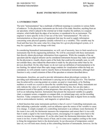
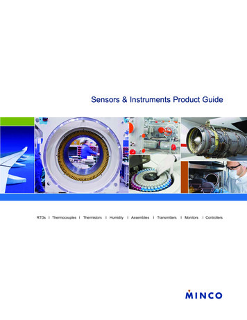
www.globalautomation.info2Introduction to Process Controlquality, precision, and performance. Techniques that were thought to be impossiblea few years ago have been developed to measure parameters.1.2.1Sequential Process ControlControl systems can be sequential in nature, or can use continuous measurement;both systems normally use a form of feedback for control. Sequential control is anevent-based process, in which the completion of one event follows the completion ofanother, until a process is complete, as by the sensing devices. Figure 1.1 shows anexample of a process using a sequencer for mixing liquids in a set ratio [2]. Thesequence of events is as follows:1. Open valve A to fill tank A.2. When tank A is full, a feedback signal from the level sensor tells thesequencer to turn valve A Off.3. Open valve B to fill tank B.4. When tank B is full, a feedback signal from the level sensor tells thesequencer to turn valve B Off.5. When valves A and B are closed, valves C and D are opened to let measuredquantities of liquids A and B into mixing tank C.6. When tanks A and B are empty, valves C and D are turned Off.7. After C and D are closed, start mixing motor, run for set period.8. Turn Off mixing motor.9. Open valve F to use mixture.10. The sequence can then be repeated after tank C is empty and Valve F isturned Off.1.2.2Continuous Process ControlContinuous process control falls into two categories: (1) elementary On/Off action,and (2) continuous control action.On/Off action is used in applications where the system has high inertia, whichprevents the system from rapid cycling. This type of control only has only two states,On and Off; hence, its name. This type of control has been in use for many decades,Liquid AValve ALiquidlevel AsensorLiquid BValve BTankATankBLiquidlevel BsensorMixerValve CValve DSequencerTankCMixture outValve FFigure 1.1Sequencer used for liquid mixing.
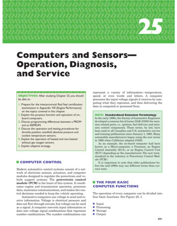
www.globalautomation.info1.2 Process Control3long before the introduction of the computer. HVAC is a prime example of this typeof application. Such applications do not require accurate instrumentation. InHVAC, the temperature (measured variable) is continuously monitored, typicallyusing a bimetallic strip in older systems and semiconductor elements in newer systems, as the sensor turns the power (manipulated variable) On and Off at presettemperature levels to the heating/cooling section.Continuous process action is used to continuously control a physical outputparameter of a material. The parameter is measured with the instrumentation orsensor, and compared to a set value. Any deviation between the two causes an errorsignal to be generated, which is used to adjust an input parameter to the process tocorrect for the output change. An example of an unsophisticated automated controlprocess is shown in Figure 1.2. A float in a swimming pool is used to continuouslymonitor the level of the water, and to bring the water level up to a set reference pointwhen the water level is low. The float senses the level, and feedback to the controlvalve is via the float arm and pivot. The valve then controls the flow of water(manipulated variable) into the swimming pool, as the float moves up and down.A more complex continuous process control system is shown in Figure 1.3,where a mixture of two liquids is required. The flow rate of liquid A is measuredwith a differential pressure (DP) sensor, and the amplitude of the signal from the DPmeasuring the flow rate of the liquid is used by the controller as a reference signal(set point) to control the flow rate of liquid B. The controller uses a DP to measurethe flow rate of liquid B, and compares its amplitude to the signal from the DP monitoring the flow of liquid A. The difference between the two signals (error signal) isused to control the valve, so that the flow rate of liquid B (manipulated variable) isdirectly proportional to that of liquid A, and then the two liquids are combined [3].FeedbackValveManipulatedvariable (Flow)Fluid inMeasuredvariable (Level)PivotFloat (Level Sensor)Figure 1.2Automated control system.Liquid ADPControllerDPLiquid BFigure 1.3Continuous control for liquid mixing.Mixture out
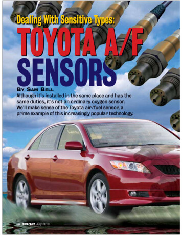
www.globalautomation.info41.3Introduction to Process ControlDefinition of the Elements in a Control LoopIn any process, there are a number of inputs (i.e., from chemicals to solid goods).These are manipulated in the process, and a new chemical or component emerges atthe output. To get a more comprehensive look at a typical process control system, itwill be broken down into its various elements. Figure 1.4 is a block diagram of theelements in a continuous control process with a feedback loop.Process is a sequence of events designed to control the flow of materials througha number of steps in a plant to produce a final utilitarian product or material. Theprocess can be a simple process with few steps, or a complex sequence of events witha large number of interrelated variables. The examples shown are single steps thatmay occur in a process.Measurement is the determination of the physical amplitude of a parameter of amaterial; the measurement value must be consistent and repeatable. Sensors are typically used for the measurement of physical parameters. A sensor is a device that canconvert the physical parameter repeatedly and reliably into a form that can be usedor understood. Examples include converting temperature, pressure, force, or flowinto an electrical signal, measurable motion, or a gauge reading. In Figure 1.3, thesensor for measuring flow rates is a DP cell.Error Detection is the determination of the difference between the amplitude ofthe measured variable and a desired set reference point. Any difference between thetwo is an error signal, which is amplified and conditioned to drive a control element.The controller sometimes performs the detection, while the reference point is normally stored in the memory of the controller.Controller is a microprocessor-based system that can determine the next step tobe taken in a sequential process, or evaluate the error signal in continuous processcontrol to determine what action is to be taken. The controller can normally condition the signal, such as correcting the signal for temperature effects or nonlinearityin the sensor. The controller also has the parameters of the process input controlelement, and conditions the error sign to drive the final element. The controller canmonitor several input signals that are sometimes interrelated, and can drive several control elements simultaneously. The controllers are normally referred to asprogrammable logic controllers (PLC). These devices use ladder networks for programming the control functions.Set ariableamplitudeFeedback signalManipulatedvariableFigure lementControlledvariableBlock diagram of the elements that make up the feedback path in a process control
www.globalautomation.info1.4 Instrumentation and Sensors5Control Element is the device that controls the incoming material to the process(e.g., the valve in Figure 1.3). The element is typically a flow control element, andcan have an On/Off characteristic or can provide liner control with drive. The control element is used to adjust the input to the process, bringing the output variable tothe value of the set point.The control and measuring elements in the diagram in Figure 1.4 are oversimplified, and are broken down in Figure 1.5. The measuring element consists of a sensor to measure the physical property of a variable, a transducer to convert the sensorsignal into an electrical signal, and a transmitter to amplify the electrical signal, sothat it can be transmitted without loss. The control element has an actuator, whichchanges the electrical signal from the controller into a signal to operate the valve,and a control valve. In the feedback loop, the controller has memory and a summingcircuit to compare the set point to the sensed signal, so that it can generate an errorsignal. The controller then uses the error signal to generate a correction signal tocontrol the valve via the actuator and the input variable. The function and operation of the blocks in different types of applications will be discussed in a later chapter. The definitions of the terms used are given at the end of the chapter.1.4Instrumentation and SensorsThe operator’s control function has been replaced by instruments and sensors thatgive very accurate measurements and indications, making the control functiontotally operator-independent. The processes can be fully automated. Instrumentation and sensors are an integral part of process control, and the quality of processcontrol is only as good as its measurement system. The subtle difference between aninstrument and a sensor is that an instrument is a device that measures and displaysthe magnitude of a physical variable, whereas a sensor is a device that measures theamplitude of a physical variable, but does not give a direct indication of the value.The same physical parameters normally can be applied to both devices [4].1.4.1Instrument ParametersThe choice of a measurement device is difficult without a good understanding of theprocess. All of the possible devices should be carefully considered. It is alsoimportant to understand instrument terminology. ANSI/ISA-51.1-R1979 (R1993)From ControllerTo ComparatorTransmitterControlelement ActuatorMeasuringelementValveMaterial flowFigure 1.5Breakdown of measuring and control elements. TransducerSensorMaterial flow
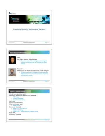
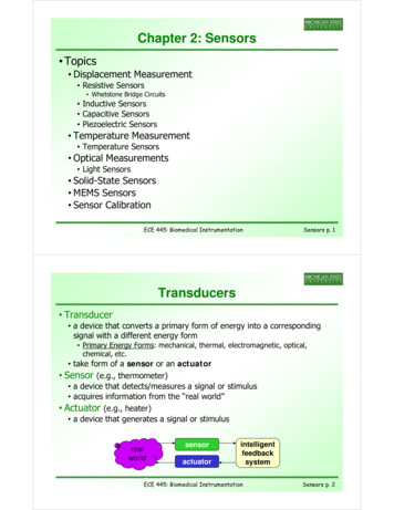
www.globalautomation.info6Introduction to Process ControlProcess Instrumentation Terminology gives the definitions of the terms used ininstrumentation in the process control sector. Some of the more common terms arediscussed below.Accuracy of an instrument or device is the error or the difference between theindicated value and the actual value. Accuracy is determined by comparing an indicated reading to that of a known standard. Standards can be calibrated devices, andmay be obtained from the National Institute of Standards and Technology (NIST).The NIST is a government agency that is responsible for setting and maintainingstandards, and developing new standards as new technology requires it. Accuracydepends on linearity, hysteresis, offset, drift, and sensitivity. The resulting discrepancy is stated as a plus-or-minus deviation from true, and is normally specified as apercentage of reading, span, or of full-scale reading or deflection (% FSD), and canbe expressed as an absolute value. In a system where more than one deviation isinvolved, the total accuracy of the system is statistically the root mean square (rms)of the accuracy of each element.Example 1.1A pressure sensor has a span of 25 to 150 psi. Specify the error when measuring 107psi, if the accuracy of the gauge is (a) 1.5% of span, (b) 2% FSD, and (c) 1.3%of reading.a. Error 0.015 (150 25) psi 1.88 psi.b. Error 0.02 150 psi 3 psi.c. Error 0.013 103 psi 1.34 psi.Example 1.2A pressure sensor has an accuracy of 2.2% of reading, and a transfer function of27 mV/kPa. If the output of the sensor is 231 mV, then what is the range of pressuresthat could give this reading?The pressure range 231/27 kPa 2.2% 8.5 kPa 2.2% 8.313 to 8.687 kPaExample 1.3In a temperature measuring system, the transfer function is 3.2 mV/k 2.1%, andthe accuracy of the transmitter is 1.7%. What is the system accuracy?System accuracy [(0.021)2 (0.017)2]1/2 2.7%Linearity is a measure of the proportionality between the actual value of a variable being measured and the output of the instrument over its operating range. Thedeviation from true for an instrument may be caused by one or several of the abovefactors affecting accuracy, and can determine the choice of instrument for a particular application. Figure 1.6 shows a linearity curve for a flow sensor, which is the output from the sensor versus the actual flow rate. The curve is compared to a best-fitstraight line. The deviation from the ideal is 4 cm/min., which gives a linearity of 4% of FSD.
www.globalautomation.info1.4 Instrumentation and Sensors710Actual curveOutput (volts)86Best fit linear4240020406080100Flow cm/minFigure 1.6 Linearity curve or a comparison of the sensor output versus flow rate, and the best-fitstraight line.Sensitivity is a measure of the change in the output of an instrument for achange in the measured variable, and is known as a
Use of a term in this book should not be regarded as affecting the validity of any trade-mark or service mark. International Standard Book Number: 1-58053-011-7 . 1.3 Definition of the Elements in a Control Loop 4 1.4 Instrumentation and Sensors 5 1.4.1 Instrument Parameters 5 1.5 Control