Transcription
Standards Defining Temperature Sensors Burns EngineeringStandards Defining Temperature SensorsYour Host and Presenter2HostJeff Wigen, National Sales Manager 24 years in sales and marketing of custom designedmade-to-order products for the industrial and biotechmarkets.PresenterBill Bergquist, Sr. Applications Engineer and RTDologistTM 30 years experience in temperature measurement withRTDs and thermocouples in the aerospace, industrial,and laboratory markets. Burns EngineeringStandards Defining Temperature SensorsTopics Covered TodayWhy do I care about standards?Resistance Temperature Detector (RTD) standards RTD history Common standards Uncommon standardsASTM E20Thermocouple StandardsOther thermometer types ASME B40.9Thermowell Standards ASME PTC 19.3 TW-2010 ASME B16.5 flange ASME B16.11 socket weld and threaded fittingsASME-BPE3A Sanitary Standards Burns EngineeringStandards Defining Temperature Sensors3
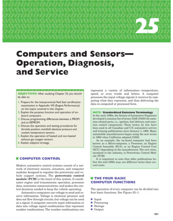
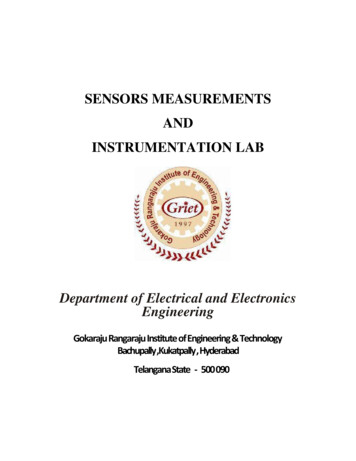
RTD History4*The application of the tendency ofelectrical conductors to increasetheir electrical resistance with risingtemperature was first described bySir William Siemens at the BakerianLecture of 1871 before the RoyalSociety of Great Britain. Thenecessary methods of constructionwere established by Callendar,Griffiths, Holborn and Wein between1885 and 1900.The RTD (resistance temperature detector) was firstdescribed in 1871. In the US the oldest patent I couldfind was from 1922 and it was for an improvement.Electrical Resistance Thermometer,U.S. patent 1,411,396, was issuedon April 4, 1922 to C.H. Wilson andC.J. Brown* From Wikipedia: http://en.wikipedia.org/wiki/Resistance thermometer#History Burns EngineeringStandards Defining Temperature SensorsFirst RTD Standard5*Callendar gave a detailed review of gas thermometry at the 1899meeting of the British Association for the Advancement of Science(BAAS) and made these recommendations: Platinum resistance thermometer be adopted as the defininginstrument of the scale Calibrated at the freezing point of water and the boiling points ofwater and sulphur Particular batch of platinum wire be selected from which thethermometers defining the scale be manufactured Wanted the scale to be called the British Association Scale ofTemperature Related to the ideal temperature scale through chosen gasthermometer measurements of the sulphur pointThe oldest evidence of a standard for RTDs wassuggested by Hugh Longbourne Callendar in 1899 inwhich he identified platinum as the best metal to use.He used the ice point and boiling points of water andsulphur for temp scales/its-27.html Burns EngineeringStandards Defining Temperature SensorsTemperature Standards6*ASTM Committee E20 on Temperature Measurement was formed in1962. Meets twice a year in May and November Has 40 members that attend 2 days of technical meetings Current membership of approximately 120 has jurisdiction over43 standards, published in the Annual Book of ASTM Standards,Volume 14.03 6 technical subcommittees These standards have and continue to play a preeminent role inall aspects of temperature measurement*http://www.astm.org/COMMITTEE/E20.htm Burns EngineeringStandards Defining Temperature SensorsToday the ASTM E20 committee meets twice a year toupdate and write standards that define and controltemperature measurement.
Temperature Standards7E20.02 Radiation ThermometryE20.03 Resistance ThermometersE20.04 ThermocouplesE20.05 Liquid-in-Glass Thermometers and HydrometersE20.07 Fundamentals in ThermometryE20.09 Digital Contact ThermometersE20.90 ExecutiveE20.91 Editorial and TerminologyE20.94 PublicationE20.96 Newer Thermometers and Techniques Burns EngineeringThe list of standards covers every type of sensor fromRTDs and thermocouples to non-contact types andalso any new technology.Standards Defining Temperature SensorsTemperature Standards8E20.03 Resistance Thermometers E644-11 Standard Test Methods for Testing Industrial ResistanceThermometers E879-12 Standard Specification for Thermistor Sensors forGeneral Purpose and Laboratory Temperature Measurements E1137/E1137M-08 Standard Specification for Industrial PlatinumResistance Thermometers E2593-12 Standard Guide for Accuracy Verification of IndustrialPlatinum Resistance Thermometers E2821-13 Standard Specification for Compacted MineralInsulated, Metal-Sheathed Cable Used in Industrial ResistanceThermometers Burns EngineeringWithin the subgroup resistance thermometers, thereare further standards that cover testing, accuracyverification, materials of construction, andperformance. Of these, the ASTM E1137 is the onethat covers the platinum resistance thermometer.Standards Defining Temperature SensorsRTD Standards (International)9IEC 60751 supersedes DIN 43760 Interchangeability tolerance classes, wire color codes, expandsthe range of alpha values used in CVD equations R vs. T tablesIn addition, the IEC standard covers performanceparameters such as hysteresis and time response. Burns EngineeringStandards Defining Temperature Sensors
RTD Standards (USA)10ASTM E1137 Similar to IEC 60751, interchangeability tolerances are smaller R vs. T tables Burns EngineeringStandards Defining Temperature SensorsRTD Calibration Standards11IPTS-68 – defines temperature scale and transfer standard, Callendarvan Dusen equationITS-90 – improved version of IPTS 68Calibration of RTDs ISO/IEC 17025 ANSI/NCSL Z540-1 Burns EngineeringStandards Defining Temperature SensorsRTD Standards12Four most important items from the standards - IMO Interchangeability Insulation resistance R vs. T tables Lead wire color codes Burns EngineeringAccredited labs follow the IEC 17025 and ASNI/NCSLZ540 standards. This insures a consistent outcome ofcalibration information.Standards Defining Temperature SensorsI pulled four items from the standards that I considerthe most important for RTDs. These are necessary tospecify a sensor and insure that it is performingcorrectly for an accurate temperature measurement.
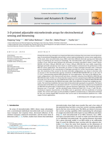
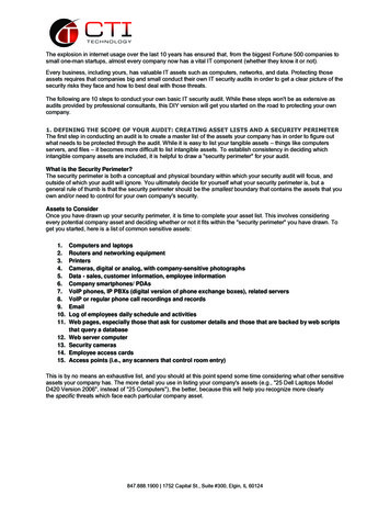
RTD StandardsStandardASTM E1137ASTM E1137IEC 607512IEC 60751IEC 60751IEC 60751213ToleranceGrade AGrade BClass AAClass AClass BClass CDefining Equation¹ [ .13 0.0017 t ] [ .25 0.0042 t ] [ .1 0.0017 t ] [ .15 0.002 t ] [ .3 0.005 t ] [ .6 0.01 t ]In a perfect world, the RTD manufacturer would buildsensors to the nominal values. Unfortunately that isnot possible so the standards define a tolerance bandcalled the “interchangeability”. These equations canbe used to calculate the interchangeability at anytemperature. Note that the temperature ‘t’ is anabsolute value in C. The resultant is theinterchangeability in C.Note 1: t absolute value of temperature of interest in CStandards Defining Temperature Sensors Burns EngineeringRTD StandardsInterchangeability144IEC Class BNote that the ASTM standard has slightly tightertolerances for the two grades of sensors. All RTDs arebuilt with the tightest tolerance at 0 C and as thetemperature diverges from 0 C the toleranceincreases. The vertical line on the graph represents0 C and the tolerance on the y axis is expressed in C from nominal.ASTM Grade B32IEC Class AASTM Grade ATolerance ( C)10-300-200-1000100200300400500600700800ASTM Grade A-1IEC Class A-2ASTM Grade B-3IEC Class B-4Temperature ( C) Burns EngineeringStandards Defining Temperature SensorsRTD Standards15Insulation resistance is the first and most important electrical check tomake on an RTD Low IR can cause a low temperature measurement due toshunting between the sensing element wires Most IR failures are due to moisture and/or contaminants thatmay have entered the probe Burns EngineeringStandards Defining Temperature SensorsThis is a typical wire wound sensing element. Theyare about 1” long and 1/16” diameter and are pottedinside a stainless steel sheath. If moisture gets intothe sheath and/or sensing element the result can be ashorter path for the excitation current and the result isa low resistance measurement.
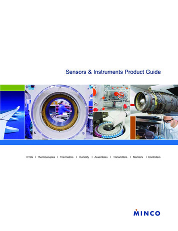
Insulation Resistance16Insulation Resistance (IR) decreases with an increasein temperature so at room temperature a value muchhigher than what is really needed for an accuratemeasurement is required. Industrial Grade RTDaccuracy is not significantly affected until the IR dropsbelow a few megohms. The measurement is made bytouching one lead of a megohmeter to the leads andthe other to the probe sheath. Some Industrial Gradeprobes are tested to higher levels to insure maximumperformance at high temperatures.Test method Lower insulation resistance lower measured temperature Test at 50 VDC IR should be 100 megohms at 25 C Burns EngineeringStandards Defining Temperature SensorsRTD Standards17IEC 60751 leadwire colorsLead wire color mayvary bymanufacturer Burns EngineeringStandards Defining Temperature SensorsRTD Standards18Other less common standards JJG 229 Chinese – similar to IEC BS-1904 – similar to IEC JIS C 1604 – equivalent to IEC, adds .003916 Edison Curve 7 - Nickel 120 ohm SAMA RC21-4-1996 - .003923, Copper 10 ohm US Department of Defense MIL-T-24388 - 0.00392 100 Burns EngineeringStandards Defining Temperature Sensors
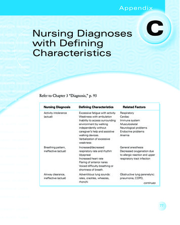
Thermocouple Standards19ASTM E230 / ANSI MC96.1 Contains reference tables for temperature-electromotive force (emf)relationships for types B, E, J, K, N, R, S, T, and C thermocouples standard and special limits of error tolerances on initial values of emf versustemperature insulation color coding for thermocouple and thermocouple extension wires Upper temperature limits Negative lead is redIEC 60584 Most widely used standard Negative lead is whiteOther standards NBS Monograph 125 and BS 4937 parts 1-7 emf tables BS 1843 UK and Czech Republic DIN 43710 Germany JIS C1610 Japan NFC 42-324 FranceThe biggest difference in the thermocouple standardsis how the lead wire colors are designated.Standards Defining Temperature Sensors Burns EngineeringThermocouple Standards20ANSI and IEC color code differencesThermocouple TypeANSIIEC lead/- lead lead/- dPink/WhiteIt is necessary to know the standard that thethermocouple was built to when identifying athermocouple by color code. There are otherstandards with different color codes depending onwhich part of the world you’re in but these are the twomost common.Standards Defining Temperature Sensors Burns EngineeringThermocouple21Limits of error ASTM E230 / ANSI MC 96.1Temperature Range & Initial Calibration d Limits*Special Limitsgreater ofgreater ofT-200 C to 350 C 1.0 C or 0.75% 0.5 C or 0.4% **J0 C to 750 C 2.2 C or 0.75% 1.1 C or 0.4%E-200 C to 870 C 1.7 C or 0.5% 0.5 C or 0.4% ***K0 C to 1180 C 2.2 C or 0.75% 1.1 C or 0.4%* % applies to temperature measured in C** -200 C to -62.5 C error is 0.8%*** -200 C to -170 C error is 0.8% Burns EngineeringStandards Defining Temperature SensorsInitial accuracy of a thermocouple is defined by thestandards as either ‘Standard’ or ‘Special Limits ofError’. Expressed as degrees C or F or % ofreading, whichever is greater.
Other Temperature Standards22ASME B40.200 Consolidation and revision of four individual standards B40.3, Bimetallic Actuated Thermometers B40.4, Filled System Thermometers B40.8, Liquid-in-Glass Thermometers B40.9, Thermowells for Thermometers These individual standards provide terminology and definitions,dimensions, safety, construction and installation issues, testprocedures and general recommendations. Burns EngineeringStandards Defining Temperature SensorsThermowells23RTDs and thermocouples are often protected with a thermowell.Strength and wake frequency factors need to be considered andthere is a standard that defines safe configurations ASME PTC 19.3 TW-2010 Wake frequency and strength calculations– Uses length, diameter, material, fluid properties, andtemperature to estimate a safe flow velocity Immersion length – balance between sufficient length to avoidstem conduction and still stay within wake frequency andstrength limits. Too long and it may break, too short and you willhave an inaccurate measurement. Burns EngineeringStandards Defining Temperature SensorsASME PTC 19.3 TW-2010*ASME PTC 19.3 TW - 2010PTC 19.3 TW-2010 is a completely new standard that establishesthe practical design considerations for thermowell installations in power andprocess piping. This code is an expanded version of the thermowell sectioncontained in the PTC 19.3-1974, and incorporates the latest theory in the areasof natural frequency, Strouhal frequency, in-line resonance and stress evaluation.ASME responded to changing industry demands for a more comprehensive setof thermowell evaluations. Key enhancements over the 1974 edition include: Expanded coverage for thermowell geometry Natural frequency correction factors for mounting compliance,added fluid mass, and sensor mass Consideration for partial shielding from flow Intrinsic thermowell damping Steady state and dynamic stress evaluations Improved allowable fatigue limit odes/PrintBook/25750.pdf Burns EngineeringMeasurement accuracy can be adversely affected by athermowell unless a few precautions are taken. Wakefrequency and strength calculations are probably themost important. These calculations will tell you howfar the well can be immersed into your process basedon the flow conditions (more on this later). This has tobe balanced with the accuracy needs of the sensor tobe immersed sufficiently to prevent stem conduction orimmersion error.Finally, time response is slower with the addition of athermowell and for processes that change temperaturerapidly this can be a significant error source.Standards Defining Temperature Sensors24The new release of the Thermowell Section of thePower Test Code incorporates the latest
ASTM E230 / ANSI MC96.1 Contains reference tables for temperature-electromotive force (emf) relationships for types B, E, J, K, N, R, S, T, and C thermocouples standard and special limits of error tolerances on initial values of emf versus temperature insulation color coding for thermocouple and thermocouple extension wiresFile Size: 722KBPage Count: 12