Transcription
Sensors and Actuators B 230 (2016) 600–606Contents lists available at ScienceDirectSensors and Actuators B: Chemicaljournal homepage: www.elsevier.com/locate/snb3-D printed adjustable microelectrode arrays for electrochemicalsensing and biosensingHaipeng Yang a,b,1 , Md Taibur Rahman a,1 , Dan Du a , Rahul Panat a, , Yuehe Lin a, aSchool of Mechanical and Material Engineering, Washington State University, Pullman, WA 99164, United StatesCollege of Materials Science and Engineering, Nanshan District Key Lab for Biopolymers and Safety Evaluation, and Shenzhen Key Laboratory of SpecialFunctional Materials, Shenzhen University, Shenzhen 518060, PR Chinaba r t i c l ei n f oArticle history:Received 3 December 2015Received in revised form 9 February 2016Accepted 22 February 2016Available online 26 February 2016Keywords:Microelectrode arraysMicro additive manufacturingHydrogen peroxideElectrochemical sensorBiosensora b s t r a c tPrinted electronics has emerged as an important fabrication technique that overcomes several shortcomings of conventional lithography and provides custom rapid prototyping for various sensor applications.In this work, silver microelectrode arrays (MEA) with three different electrode spacing were fabricatedusing 3-D printing by the aerosol jet technology. The microelectrodes were printed at a length scaleof about 15 m, with the space between the electrodes accurately controlled to about 2 times (30 m,MEA30), 6.6 times (100 m, MEA100) and 12 times (180 m, MEA180) the trace width, respectively.Hydrogen peroxide and glucose were chosen as model analytes to demonstrate the performance of theMEA for sensor applications. The electrodes are shown to reduce hydrogen peroxide with a reductioncurrent proportional to the concentration of hydrogen peroxide for certain concentration ranges. Further, the sensitivity of the current for the three electrode configurations was shown to decrease withan increase in the microelectrode spacing (sensitivity of MEA30:MEA100:MEA180 was in the ratio of3.7:2.8:1), demonstrating optimal MEA geometry for such applications. The noise of the different electrode configurations is also characterized and shows a dramatic reduction from MEA30 to MEA100 andMEA180 electrodes. Further, it is shown that the response current is proportional to MEA100 and MEA180electrode areas, but not for the area of MEA30 electrode (the current density of MEA30:MEA100:MEA180is 0.25:1:1), indicating that the MEA30 electrodes suffer from diffusion overlap from neighboring electrodes. The work thus establishes the lower limit of microelectrode spacing for our geometry. The lowestdetection limit of the MEAs was calculated (with S/N 3) to be 0.45 M. Glucose oxidase was immobilizedon MEA100 microelectrodes to demonstrate a glucose biosensor application. The sensitivity of glucosebiosensor was 1.73 A mM 1 and the calculated value of detection limit (S/N 3) was 1.7 M. The electrochemical response characteristics of the MEAs were in agreement with the predictions of existingmodels. The current work opens up the possibility of additive manufacturing as a fabrication techniquefor low cost custom-shaped MEA structures that can be used as electrochemical platforms for a widerange of sensor applications. 2016 Elsevier B.V. All rights reserved.1. IntroductionAn array of microelectrodes (MEA) shows many advantagesover a conventional (individual) microelectrode such as increasedmass transport, fast response times, decreased influence of thesolution resistance, enhanced sensitivities, and the lower limit ofdetection (LOD) [1–3]. Further, studies have shown that individual Corresponding authors.E-mail addresses: rahul.panat@wsu.edu (R. Panat), yuehe.lin@wsu.edu,yuehe.lin@pnnl.gov (Y. Lin).1These authors contributed equally to this 25-4005/ 2016 Elsevier B.V. All rights reserved.microelectrodes show high mass-transfer flux and a low value ofthe potential drop, but have a very low current carrying capabilitydue to the low cross section area. The MEAs are shown to increasethe current carrying capability while maintaining the advantagesof a single microelectrode with respect to mass diffusion and ohmicdrop [4]. Each microelectrode of an MEA, however, has a diffusion layer associated with it. In order to make each electrode workas an individual microelectrode, the spacing between electrodes(for a given electrode width) in an MEA needs to be sufficientlylarge to avoid the diffusion layer overlap with the adjacent electrodes [5,6]. Since the noise level depends on the dimension ofthe individual electrodes whereas the signal strength depends onthe total surface area of the electrodes, the size reduction of each
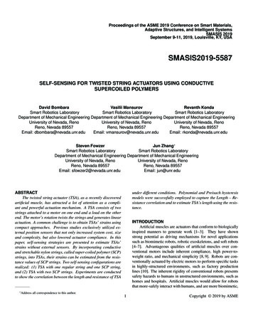
H. Yang et al. / Sensors and Actuators B 230 (2016) 600–606individual electrode and the increase of the total number of electrodes, as in an MEA, is shown to improve the signal-to-noise (S/N)ratio and achieve lower LOD [5,7]. An excellent sensor action canbe obtained by controlling the space between each microelectrodeof MEAs to achieve maximum number of electrodes and avoid theoverlap of the diffusion layer, while using the individual microelectrode for the sensing action.Previously, lithography, template methods, or chemical selfassembly were explored to fabricate micro/nanoelectrode arrays[8–12]. Such methods typically involve the use of harmful chemicals, multiple fabrication steps and create material waste [13,14].In addition, the material choices for sensor platforms are ratherrestricted due to the substrate compatibility with the chemicalprocesses used. Lastly, a need for customized biosensors to eachindividual is emerging in specific applications which requires rapidchanges in sensor circuitry to change the detection range and/orlimit. The above fabrication techniques are not suitable for suchrapid and customized changes to circuitry without resulting in asignificant cost increase. Recently, direct write 3-D printing hasbecome a valuable technique in a wide variety of applications,such as chemistry reaction container [15,16], microfluidics [17],sensors [18], photodetectors [19], graphene interconnects [20],and biomimetic structures [21]. However, few works have beenachieved on the fabrication of microelectrode arrays with 3D printing technique [22]. The direct write printing method can ‘write’microelectronic circuit on any surface without requiring the useof harmful chemicals and without creating material waste [23,24].In addition to being scalable, this technique can allow rapid andcustomized changes to sensor design. Lastly, direct-write techniques can create sensors on any substrate as long as the substrateis hydrophilic and it allows highly complex/dense metal-polymercircuitry required for the electrochemical detection.In this paper, we report design and direct-write fabricationof MEAs with adjustable array spacing as a platform for electrochemical sensing. The space between microelectrodes of the threefabricated MEAs is controlled to be 30, 100, and 180 m, respectively. By using direct write 3D printing technique, it is easy tofind the minimum spacing between electrodes on MEAs to getthe maximum signal-to-noise (S/N) ratio. Sensor performance isdemonstrated through the detection of hydrogen peroxide and glucose, chosen as model analytes. The sensitivity and accuracy ofdetection was determined as a function of the printed MEA structure geometry. The potential applications of this method for othertypes of electrochemical sensors are also discussed.601Fig. 1. Schematic of an aerosol jet micro-additive printer.2.1. Micro-electrode array fabricationfurt, Germany) and a UV curable polymer (Loctite 3105, HenkelCorporation, Düsseldorf, Germany). The silver nanoparticles had asize of about 30–50 nm with about 40 2 wt% particle loading inthe ink and a viscosity of about 1.5 cP according to the manufacturer data sheet. The viscosity of Loctite 3105 was 300 cP and wasprinted using pneumatic atomizer of the AJ system. Before printing the structures, ink material was placed in a tube which wasrotated continuously around its axis for 12 h using a tube roller(Scilogex MX-T6-S, Rocky Hill, CT, USA) to prevent nanoparticleagglomeration within the ink. UV curable Loctite 3105 was storedwithout exposure to ambient light prior to printing. A transparentglass slide (Thermo Fisher Scientific, Waltham, MA, USA) was usedas the substrate. Prior to printing, the substrates were cleaned inDI water followed by isopropyl alcohol. In order to make the substrate surface hydrophilic and to promote better adhesion of theprinted material, the substrate was treated with an atmosphericplasma (AtomfloTM 400, Surfx Technologies LLC, Redondo Beach,CA, USA) at 100 W for 5 min.In the current study, we used both, the ultrasonic and the pneumatic atomizer. The nozzle exit diameter to print the Ag electrodelines was 150 m (the minimum line width is about 10 timessmaller than the nozzle diameter based upon the sheath gas pressure). Three types of nozzle exit diameters, 150 m, 250 m, and300 m was used to print Loctite 3105 in order to achieve differenttrace width 30 m, 100 m, and 180 m. While printing, the tip-tosubstrate distance was always kept at 3 mm. All other parametersmentioned in Table 1 were optimized for the current work. Thedetails for Ag and polymer printing is presented in following subsections.The MEAs were fabricated using aerosol jet (AJ) baseddirect-write technology that allows deposition of solvent basednanoparticles with solution viscosity ranging from 1 to 1000 cP.A schematic of the AJ system (AJ 300, Optomec Inc., Albuquerque,NM, USA) is shown in Fig. 1 and includes two atomizers (ultrasonicand pneumatic), a programmable XY motion stage, and a deposition head. Solvent based nanoparticle ink is placed in the atomizerwhich creates a continuous and dense mist of nanoparticles with adroplet size of 1–5 m which is then transferred to the depositionhead with the help of a carrier gas N2 . The mist or dense vapor isthen focused and driven towards the nozzle with the help of a secondary gas (also N2 ) to form a micro-jet. A UV apparatus (UJ35UV cure subsystem, Panasonic Corporation, Osaka, Japan) connected to the machine can instantaneously cure the (UV curable)polymer. Primary materials used to fabricate the biosensor weresilver nanoparticle ink (Perfect-TPS 40 G2, Clariant Group, Frank-a) Additive fabrication of micro electrode: a nanoparticle Ag inkis dispensed on the glass substrate using ultrasonic atomizer inorder to fabricate conductive Ag traces at a length scale down totens of micrometre. Before printing geometry of the conductivepart was drawn in AutoCad (Autodesk, 2015) and converted toprg file compatible to the AJ software. The nozzle exit diameter used to print Ag traces was 150 m. An atomizing flow rateof 25 sccm and a sheath gas flow rate of 50 sccm was used forprinting. Width of the printed traces measured by a compoundmicroscope was 15 1.04 m. The fingers of the sensors including interconnect and probing pad was printed using a singlelayer of printed material. During printing platen temperaturewas set to 80 C.b) Additive fabrication of micro-scale polymer trace: after printingthe conductive silver traces, polymer traces were printed perpendicular to the silver traces in order to create micro electrodes.2. Experimental
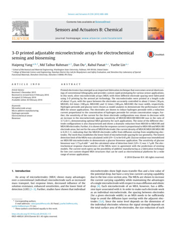
602H. Yang et al. / Sensors and Actuators B 230 (2016) 600–606Fig. 2. (a) Schematic showing the fabrication process for microelectrode arrays using an aerosol jet printer. (b) Schematic of microelectrode array. (c) Actual images of AJprinted microelectrode array at different magnifications.The polymer traces were also created using AutoCAD. Polymertraces were printed with certain distance apart from each otherin order to create sensing regions at alternate segments as shownin Fig. 2a–c. Other alternate layers were insulated by polymerlayer in order to form the micro electrodes. A UV curable polymer ink was dispensed at an accuracy of tens of micro-meter bya jetting action on top of Ag layers. The polymer ink was instantaneously cured during the dispense using a UV light source asshown in Fig. 2a. With instantaneous curing, it was possible tocreate solidified polymer layer maintaining the required width.Three different polymer trace widths were used for the threeMEAs (see Table 1). By varying different printing parameters,efforts were made to keep micro electrode array width close to30 m. During printing, the UV power was set to 30% of the maximum capability (940 mW). Platen temperature for polymer traceprinting was 80 C as well. All completed sensors were thermallysintered in Vulcan 3–550 programmable furnace (Degussa-NeyDental Inc., Bloomfield, CT, USA) at 100 C for 15 min followed byair cooling according to manufacturer guideline. Sintering is necessary in order to have conductive electrode lines. The resistivityof the Ag sintered by this method is about 2 10 7 -m (manufacturer data sheet), or about an order of magnitude higher thanthe bulk resistivity.The exposed silver traces are expected to act as microelectrodearrays. The space between silver trace and the width of the polymertrace define the electrode dimension of the microelectrode arrays.To adjust the space between electrodes, we just print silver traceswith different spacing and polymer traces with a different width.2.2. Chemicals and reagentsGlucose oxidase (GOx ) was used for glucose sensor(Sigma–Aldrich, St. Louis, MO, USA) with an activity ofabout 185 units mg 1 . Hydrogen peroxide (H2 O2 ) solution(Sigma Aldrich, St. Louis MO) was stored in refrigerator before use.Nafion solution (5%), hydrogen peroxide (H2 O2 ), glutaraldehyde,and -d-glucose (Sigma–Aldrich, St. Louis MO) used in this workwere available with analytical grade purity. The stock solution ofNafion, H2 O2 and glutaraldehyde were stored in refrigerator beforeuse. Electrochemical measurements were carried out in a 0.1 Mphosp
in Vulcan 3–550 programmable furnace (Degussa-Ney Dental Inc.,Bloomfield,CT,USA)at100 Cfor15minfollowedby air snec-essary 2.3. ty of theAgsinteredbythismethodisabout2 10 7-m(manu-facturer Cyclic datasheet),oraboutanorderofmagnitudehigherthan the