Transcription
BASIC INSTRUMENTATIONMEASURING DEVICESANDBASIC PID CONTROL
Science and Reactor Fundamentals – Instrumentation & ControlCNSC Technical Training GroupiTable of ContentsSection 1 - OBJECTIVES . 3Section 2 - INSTRUMENTATION EQUIPMENT . 72.02.1INTRODUCTION . 7PRESSURE MEASUREMENT . 72.1.1 General Theory . 72.1.2 Pressure Scales. 72.1.3 Pressure Measurement . 82.1.4 Common Pressure Detectors. 92.1.5 Differential Pressure Transmitters . 112.1.6 Strain Gauges . 132.1.7 Capacitance Capsule . 142.1.8 Impact of Operating Environment . 152.1.9 Failures and Abnormalities . 162.2 FLOW MEASUREMENT. 182.2.1 Flow Detectors . 182.2.2 Square Root Extractor. 252.2.3 Density Compensating Flow Detectors . 292.2.4 Flow Measurement Errors. 312.3 LEVEL MEASUREMENT . 332.3.1 Level Measurement Basics . 332.3.2 Three Valve Manifold. 342.3.3 Open Tank Measurement. 362.3.4 Closed Tank Measurement . 362.3.5 Bubbler Level Measurement System . 422.3.6 Effect of Temperature on Level Measurement . 442.3.7 Effect of Pressure on Level Measurement . 472.3.8 Level Measurement System Errors. 472.4 TEMPERATURE MEASUREMENT . 492.4.1 Resistance Temperature Detector (RTD). 492.4.2 Thermocouple (T/C) . 522.4.3 Thermal Wells. 542.4.4 Thermostats. 552.5 NEUTRON FLUX MEASUREMENT . 592.5.1 Neutron Flux Detection. 592.5.2 Neutron Detection Methods. 602.5.3 Start-up (sub-critical) Instrumentation. 612.5.4 Fission neutron detectors . 632.5.5 Ion chamber neutron detectors. 642.5.6 In-Core Neutron Detectors. 702.5.7 Reactor Control at High Power. 772.5.8 Overlap of Neutron Detection. 78REVIEW QUESTIONS - EQUIPMENT . 81Revision 1 – January 2003
Science and Reactor Fundamentals – Instrumentation & ControlCNSC Technical Training GroupiiSection 3 - CONTROL . 893.03.13.23.33.43.53.63.73.8INTRODUCTION . 89BASIC CONTROL PRINCIPLES . 893.1.1 Feedback Control . 913.1.2 Feedforward Control. 913.1.3 Summary . 92ON/OFF CONTROL . 933.2.1 Summary . 94BASIC PROPORTIONAL CONTROL . 953.3.1 Summary . 97Proportional Control . 983.4.1 Terminology. 983.4.2 Practical Proportional Control . 983.4.3 Summary . 105Reset of Integral Action . 1063.5.1 Summary . 109RATE OR DERIVATIVE ACTION . 1103.6.1 Summary . 115MULTIPLE CONTROL MODES. 116TYPICAL NEGATIVE FEEDBACK CONTROL SCHEMES 1173.8.1 Level Control . 1173.8.2 Flow Control . 1183.8.3 Pressure Control. 1193.8.4 Temperature Control. 120REVIEW QUESTIONS - CONTROL . 122Revision 1 – January 2003
Science and Reactor Fundamentals – Instrumentation & ControlCNSC Technical Training Group3OBJECTIVESThis module covers the following areas pertaining to instrumentation andcontrol. PressureFlowLevelTemperatureNeutron FluxControlAt the end of training the participants will be able to:Pressure explain the basic working principle of pressure measuring devices,bourdon tube, bellows, diaphragm, capsule, strain gauge,capacitance capsule;explain the basic operation of a differential pressure transmitter;explain the effects of operating environment (pressure,temperature, humidity) on pressure detectors;state the effect of the following failures or abnormalities:over-pressuring a differential pressure cell or bourdon tube;diaphragm failure in a differential pressure cell;blocked or leaking sensing lines; andloss of loop electrical power.Flow explain how devices generate a differential pressure signal: orifice,venturi, flow nozzle, elbow, pitot tube, annubar; explain how each of the following will affect the indicated flowsignal from each of the above devices:change in process fluid temperature;change in process fluid pressure; anderosion. identify the primary device, three-valve manifold and flow;transmitter in a flow measurement installation; state the relationship between fluid flow and output signal in aflow control loop with a square root extractor; describe the operation of density compensating flow detectors; explain why density compensation is required in some flowmeasurements; state the effect on the flow measurement in process withabnormalities: Vapour formation in the throat, clogging if throat byforeign material, Leaks in HI or LO pressure sensing lines;Revision 1 – January 2003Note
Science and Reactor Fundamentals – Instrumentation & ControlCNSC Technical Training Group4Level explain how a level signal is derived for: an open vessel, aclosed vessel with dry reference leg, a closed vessel with wetreference leg; explain how a DP cell can be damaged from over pressure if itis not isolated correctly; explain how a bubbler derives level signal for an open andclosed tank; explain the need for zero suppression and zero elevation in levelmeasurement installations; describe the effects of varying liquid temperature or pressure onlevel indication from a differential pressure transmitter; explain how errors are introduced into the DP cell signal byabnormalities: leaking sensing lines, dirt or debris in the sensinglines;Temperature explain the principle of operation of temperature detectors: RTD,thermocouple, bimetallic strip & pressure cylinders; state the advantages and disadvantages of RTDs andthermocouples state the effect on the indicated temperature for failures, opencircuit and short circuit;Flux state the reactor power control range for different neutron sensorsand explain why overlap is required: Start-up instrumentation, IonChambers, In Core detectors; explain how a neutron flux signal is derived in a BF3 proportionalcounter; explain the reasons for start-up instrumentation burn-out; explain how a neutron flux signal is derived in an ion chamber; state the basic principles of operation of a fission chamberradiation detector; state and explain methods of gamma discrimination for neutron ionchambers; explain how the external factors affect the accuracy of the ionchamber’s neutron flux measurement: Low moderator level, Lossof high voltage power supply, Shutdown of the reactor; describe the construction and explain the basic operating principleof in-core neutron detectors; explain reactor conditions factors can affect the accuracy of the incore detector neutron flux measurement: Fuelling or reactivitydevice movement nearby, Start-up of the reactor, long-termexposure to neutron flux, Moderator poison (shielding);Revision 1 – January 2003Note
Science and Reactor Fundamentals – Instrumentation & ControlCNSC Technical Training Group 5explain the reasons for power control using ion chambers at lowpower and in-core detectors at high power;Control identify the controlled and manipulated variables; sketch a simple block diagram and indicate set point,measurement, error, output and disturbances; state the difference between open and closed loop control; state the basic differences between feedback and feed forwardcontrol; explain the general on/off control operation; explain why a process under on/off control is not controllable atthe set point; explain why on/off control is suitable for slow respondingprocesses; explain the meaning of proportional control in terms of therelationship between the error signal and the control signal; explain why offset will occur in a control system, withproportional control only; choose the controller action for corrective control; convert values of PB in percentage to gain values and vice-versa; determine the relative magnitude of offset with respect to theproportional band setting; state the accepted system response, i.e., ¼ decay curve, following adisturbance; explain the reason for the use of reset (integral) control and itsunits; sketch the open loop response curve for proportional plus resetcontrol in response to a step disturbance; state two general disadvantages of reset control with respect tooverall loop stability and loop response if the control setting isincorrectly adjusted; calculate the reset action in MPR or RPM given a control system’sparameters; state, the purpose of rate or derivative control; state the units of derivative control; justify the use of rate control on slow responding processes suchas heat exchangers; explain why rate control is not used on fast respondingprocesses. sketch the open loop response curve for a control system withproportional plus derivative control modes; state which combinations of the control modes will most likelybe found in typical control schemes;Revision 1 – January 2003Note
Science and Reactor Fundamentals – Instrumentation & ControlCNSC Technical Training Group sketch typical control schemes for level, pressure, flow andtemperature applications.Revision 1 – January 20036Note
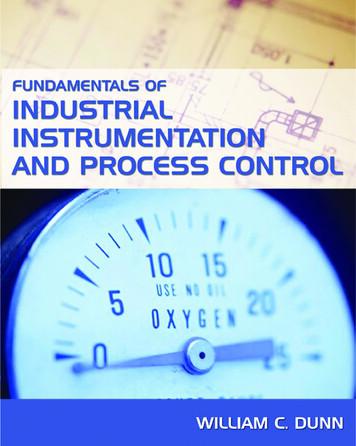
Science and Reactor Fundamentals – Instrumentation & ControlCNSC Technical Training Group7INSTRUMENTATION EQUIPMENT2.0INTRODUCTIONInstrumentation is the art of measuring the value of some plant parameter,pressure, flow, level or temperature to name a few and supplying a signalthat is proportional to the measured parameter. The output signals arestandard signal and can then be processed by other equipment to provideindication, alarms or automatic control. There are a number of standardsignals; however, those most common in a CANDU plant are the 4-20 mAelectronic signal and the 20-100 kPa pneumatic signal.This section of the course is going to deal with the instrumentationequipment normal used to measure and provide signals. We will look atthe measurement of five parameters: pressure, flow, level, temperature,and neutron flux.2.1PRESSURE MEASUREMENTThis module will examine the theory and operation of pressure detectors(bourdon tubes, diaphragms, bellows, forced balance and variablecapacitance). It also covers the variables of an operating environment(pressure, temperature) and the possible modes of failure.2.1.1 General TheoryPressure is probably one of the most commonly measured variables in thepower plant. It includes the measurement of steam pressure; feed waterpressure, condenser pressure, lubricating oil pressure and many more.Pressure is actually the measurement of force acting on area of surface.We could represent this as:PressureForceAreaorPFAThe units of measurement are either in pounds per square inch (PSI) inBritish units or Pascals (Pa) in metric. As one PSI is approximately 7000Pa, we often use kPa and MPa as units of pressure.2.1.2 Pressure ScalesBefore we go into how pressure is sensed and measured, we have toestablish a set of ground rules. Pressure varies depending on altitude abovesea level, weather pressure fronts and other conditions.The measure of pressure is, therefore, relative and pressure measurementsare stated as either gauge or absolute.Revision 1 – January 2003Note
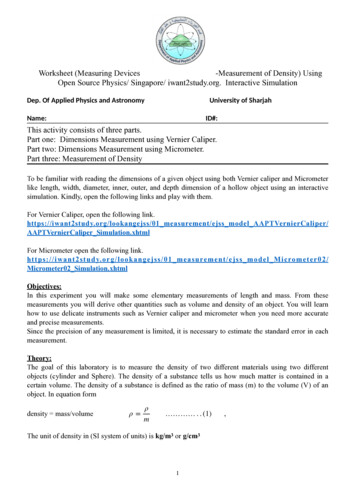
Science and Reactor Fundamentals – Instrumentation & ControlCNSC Technical Training Group8Gauge pressure is the unit we encounter in everyday work (e.g., tireratings are in gauge pressure).A gauge pressure device will indicate zero pressure when bled down toatmospheric pressure (i.e., gauge pressure is referenced to atmosphericpressure). Gauge pressure is denoted by a (g) at the end of the pressureunit [e.g., kPa (g)].Absolute pressure includes the effect of atmospheric pressure with thegauge pressure. It is denoted by an (a) at the end of the pressure unit [e.g.,kPa (a)]. An absolute pressure indicator would indicate atmosphericpressure when completely vented down to atmosphere - it would notindicate scale zero.Absolute Pressure Gauge Pressure Atmospheric PressureFigure 1 illustrates the relationship between absolute and gauge. Notethat the base point for gauge scale is [0 kPa (g)] or standard atmosphericpressure 101.3 kPa (a).The majority of pressure measurements in a plant are gauge. Absolutemeasurements tend to be used where pressures are below atmosphere.Typically this is around the condenser and vacuum cuumGaugeScale101.3 kPa(a)0 kPa(g)0 kPa(a)-101.3 kPa(g)Figure 1Relationship between Absolute and Gauge Pressures2.1.3 Pressure MeasurementThe object of pressure sensing is to produce a dial indication, controloperation or a standard (4 - 20 mA) electronic signal that represents thepressure in a process.To accomplish this, most pressure sensors translate pressure into physicalmotion that is in proportion to the applied pressure. The most commonpressure sensors or primary pressure elements are described below.Revision 1 – January 2003Note
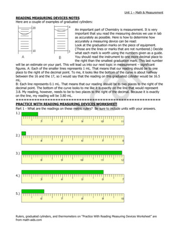
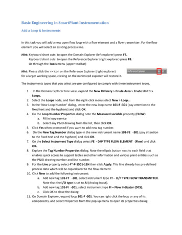
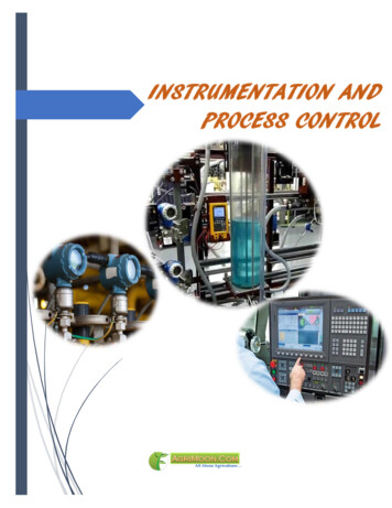
Science and Reactor Fundamentals – Instrumentation & ControlCNSC Technical Training Group9They include diaphragms, pressure bellows, bourdon tubes and pressurecapsules. With these pressure sensors, physical motion is proportional tothe applied pressure within the operating range.You will notice that the term differential pressure is often used. This termrefers to the difference in pressure between two quantities, systems ordevices2.1.4Common Pressure DetectorsBourdon TubesBourdon tubes are circular-shaped tubes with oval cross sections (refer toFigure 2). The pressure of the medium acts on the inside of the tube. Theoutward pressure on the oval cross section forces it to become rounded.Because of the curvature of the tube ring, the bourdon tube then bends asindicated in the direction of the arrow.MotionCrossSectionPressureFigure 2Bourdon TubeDue to their robust construction, bourdon are often used in harshenvironments and high pressures, but can also be used for very lowpressures; the response time however, is slower than the bellows ordiaphragm.BellowsBellows type elements are constructed of tubular membranes that areconvoluted around the circumference (see Figure 3). The membrane isattached at one end to the source and at the other end to an indicatingdevice or instrument. The bellows element can provide a long range ofmotion (stroke) in the direction of the arrow when input pressure isapplied.Revision 1 – January 2003Note
Science and Reactor Fundamentals – Instrumentation & ControlCNSC Technical Training Group10MotionNoteFlexibleBellowsPressureFigure 3BellowsDiaphragmsA diaphragm is a circular-shaped convoluted membrane that is attached tothe pressure fixture around the circumference (refer to Figure 4). Thepressure medium is on one side and the indication medium is on the other.The deflection that is created by pressure in the vessel would be in thedirection of the arrow indicated.MotionFlexibleMembrane.PressureFigure 4DiaphragmDiaphragms provide fast acting and accurate pressure indication.However, the movement or stroke is not as large as the bellowsCapsulesThere are two different devices that are referred to as capsule. The first isshown in figure 5. The pressure is applied to the inside of the capsule andRevision 1 – January 2003
Science and Reactor Fundamentals – Instrumentation & ControlCNSC Technical Training Group11if it is fixed only at the air inlet it can expand like a balloon. Thisarrangement is not much different from the diaphragm except that itexpands both sureFigure 5CapsuleThe capsule consists of two circular shaped, convoluted membranes(usually stainless steel) sealed tight around the circumference. Thepressure acts on the inside of the capsule and the generated strokemovement is shown by the direction of the arrow.The second type of capsule is like the one shown in the differentialpressure transmitter (DP transmitter) in figure 7. The capsule in the bottomis constructed with two diaphragms forming an outer case and the interspace is filled with viscous oil. Pressure is applied to both side of thediaphragm and it will deflect towards the lower pressure.To provide over-pressurized protection, a solid plate with diaphragmmatching convolutions is usually mounted in the center of the capsule.Silicone oil is then used to fill the cavity between the diaphragms for evenpressure transmission.Most DP capsules can withstand high static pressure of up to 14 MPa(2000 psi) on both sides of the capsule without any damaging effect.However, the sensitive range for most DP capsules is quite low. Typically,they are sensitive up to only a few hundred kPa of differential pressure.Differential pressure that is significantly higher than the capsule rangemay damage the capsule permanently.2.1.5 Differential Pressure TransmittersMost pressure transmitters are built around the pressure capsule concept.They are usually capable of measuring differential pressure (that is, theRevision 1 – January 2003Note
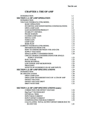
Science and Reactor Fundamentals – Instrumentation & ControlCNSC Technical Training Group12difference between a high pressure input and a low pressure input) andtherefore, are usually called DP transmitters or DP cells.Figure 6 illustrates a typical DP transmitter. A differential pressurecapsule is mounted inside a housing. One end of a force bar is connectedto the capsule assembly so that the motion of the capsule can betransmitted to outside the housing. A sealing mechanism is used where theforce bar penetrates the housing and also acts as the pivot point for theforce bar. Provision is made in the housing for high- pressure fluid to beapplied on one side of the capsule and low-pressure fluid on the other.Any difference in pressure will cause the capsule to deflect and createmotion in the force bar. The top end of the force bar is then connected to aposition detector, which via an electronic system will produce a 4 - 20 masignal that is proportional to the force bar movement.4-20mADetectorSeal and PivotForce BarSilicone Oil FillingHigh PressureLow PressureD.P. CapsuleHousingMetal DiaphragmBackup PlateFigure 6Typical DP Transmitter ConstructionThis DP transmitter would be used in an installation as shown inFigure 7.Pressure TransmitterControlled VesselPressure(20 to 30 KPa)Impulse LineIsolationValveHLVented4-20mARevision 1 – January 2003Note
Science and Reactor Fundamentals – Instrumentation & ControlCNSC Technical Training Group13Figure 7DP Transmitter ApplicationNoteA DP transmitter is used to measure the gas pressure (in gauge scale)inside a vessel. In this case, the low-pressure side of the transmitter isvented to atmosphere and the high-pressure side is connected to the vesselthrough an isolating valve. The isolating valve facilitates the removal ofthe transmitter.The output of the DP transmitter is proportional to the gauge pressure ofthe gas, i.e., 4 mA when pressure is 20 kPa and 20 mA when pressure is30 kPa.2.1.6 Strain GaugesThe strain gauge is a device that can be affixed to the surface of an objectto detect the force applied to the object. One form of the strain gauge is ametal wire of very small diameter that is attached to the surface of adevice being monitored.Resistance Ω IncreasesLength IncreasesForceAREAAREAAREAForceCross Sectional Area DecreasesFigure 8Strain GaugeFor a metal, the electrical resistance will increase as the length of themetal increases or as the cross sectional diameter decreases.When force is applied as indicated in Figure 8, the overall length of thewire tends to increase while the cross-sectional area decreases.The amount of increase in resistance is proportional to the force thatproduced the change in length and area. The output of the strain gauge is achange in resistance that can be measured by the input circuit of anamplifier.Strain gauges can be bonded to the surface of a pressure capsule or to aforce bar positioned by the measuring element. Shown in Figure 9 (nextpage) is a strain gauge that is bonded to a force beam inside the DPcapsule. The change in the process pressure will cause a resistive changein the strain gauges, which is then used to produce a 4-20 mA signal.Revision 1 – January 2003
Science and Reactor Fundamentals – Instrumentation & ControlCNSC Technical Training GroupElectronics Enclosure14Field t BoardElectronicsFeedthroughLiquid FillProcess SealDiaphragmStrain GaugeBeamOverpressureStopSensing CapsularElementFigure 9Resistive Pressure Transmitter2.1.7 Capacitance CapsuleSimilar to the strain gauge, a capacitance cell measures changes inelectrical characteristic. As the name implies the capacitance cell measureschanges in capacitance. The capacitor is a device that stores electricalcharge. It consists of metal plates separated by an electrical insulator. Themetal plates are connected to an external electrical circuit through whichelectrical charge can be transferred from one metal plate to the other.The capacitance of a capacitor is a measure of its ability to store charge.The capacitance of the capacitance of a capacitor is directly proportionalto the area of the metal plates and inversely proportional to the distancebetween them. It also depends on a characteristic of the insulating materialbetween them. This characteristic, called permittivity is a measure of howwell the insulating material increases the ability of the capacitor to storecharge.C εAdC is the capacitance in FaradsA is the area of the platesD is the distance of the platesε is the permittivity of the insulatorBy building a DP cell capsule so there are capacitors inside the cellcapsule, differential pressures can be sensed by the changes in capacitanceof the capacitors as the pressure across the cell is varied.Revision 1 – January 2003
Science and Reactor Fundamentals – Instrumentation & ControlCNSC Technical Training Group152.1.8 Impact of Operating EnvironmentAll of the sensors described in this module are widely used in control andinstrumentation systems throughout the power station.Their existence will not normally be evident because the physicalconstruction will be enclosed inside manufacturers’ packaging. However,each is highly accurate when used to measure the right quantity and withinthe rating of the device. The constraints are not limited to operatingpressure. Other factors include temperature, vapour content and vibration.VibrationThe effect of vibration is obvious in the inconsistency of measurements,but the more dangerous result is the stress on the sensitive membranes,diaphragms and linkages that can cause the sensor to fail. Vibration cancome from many sources.Some of the most common are the low level constant vibration of anunbalanced pump impeller and the larger effects of steam hammer.External vibration (loose support brackets and insecure mounting) canhave the same effect.TemperatureThe temperature effects on pressure sensing will occur in two main areas:The volumetric expansion of vapour is of course temperature dependent.Depending on the system, the increased pressure exerted is usually alreadyfactored in.The second effect of temperature is not so apparent. An operatingtemperature outside the rating of the sensor will create significant error inthe readings. The bourdon tube will indicate a higher reading whenexposed to higher temperatures and lower readings when abnormally cold- due to the strength and elasticity of the metal tube. This same effectapplies to the other forms of sensors listed.Vapour ContentThe content of the gas or fluid is usually controlled and known. However,it is mentioned at this point because the purity of the substance whosepressure is being monitored is of importance - whether gaseous or fluid –especially, if the device is used as a differential pressure device inmeasuring flow of a gas or fluid.Higher than normal density can force a higher dynamic reading dependingon where the sensors are located and how they are used. Also, the vapourdensity or ambient air density can affect the static pressure sensor readingsRevision 1 – January 2003Note
Science and Reactor Fundamentals – Instrumentation & ControlCNSC Technical Training Group16and DP cell readings. Usually, lower readings are a result of the loweravailable pressure of the substance. However, a DP sensor located in a hotand very humid room will tend to read high.2.1.9Failures and AbnormalitiesOver-PressureAll of the pressure sensors we have analyzed are designed to operate overa rated pressure range. Plant operating systems rely on these pressuresensors to maintain high accuracy over that given range. Instrumentreadings and control functions derived from these devices could placeplant operations in jeopardy if the equipment is subjected to over pressure(over range) and subsequently damaged. If a pressure sensor is overranged, pressure is applied to the point where it can no longer return to itsoriginal shape, thus the indication would return to some value greater thanthe original.Diaphragms and bellows are usually the most sensitive and fast-acting ofall pressure sensors.They are also however, the most prone to fracture on over-pressuring.Even a small fracture will cause them to read low and be less responsive topressure changes. Also, the linkages and internal movements of thesensors often become distorted and can leave a permanent offset in themeasurement. Bourdon tubes are very robust and can handle extremelyhigh pressures although, when exposed to over-pressure, they becomeslightly distended and will read high. Very high over-pressuring will ofcourse rupture the tube.Faulty Sensing LinesFaulty sensing lines create inaccurate readings and totally misrepresent theactual pressureWhen the pressure lines become partially blocked, the dynamic responseof the sensor is naturally reduced and it will have a slow response tochange in pressure. Depending on the severity of the blockage, the sensorcould even retain an incorrect zero or low reading, long after the change invessel pressure.A cracked or punctured sensing line has the characteristic of consistentlylow readings. Sometimes, there can be detectable down-swings of pressurefollowed by slow increases.Loss of Loop Electrical PowerRevision 1 – January 2003Note
Science and Reactor Fundamentals – Instrumentation & ControlCNSC Technical Training GroupAs with any instrument that relies on AC power, the output of the D/Ptransmitters will drop to zero or become irrational with a loss of powersupply.Revision 1 – January 200317Note
Science and Reactor Fundamentals – Instrumentation & ControlCNSC Technical Training Group2.218FLOW MEASUREMENTThere are various methods used to measure the flow rate of steam, water,lubricants, air, etc., in a nuclear generating station. However, in this modulewill look at the most common, namely the DP cell type flow detector. Alsoin this section we will discuss the application of a square root extractor andcut-off relay plus the possible sources of errors in flow measurements anddifferent failure modes that can occur.2.2.1 Flow DetectorsTo measure the rate of flow by the differential pressure method, some formof restriction is placed in the pipeline to create a pressure drop.
Science and Reactor Fundamentals ΠInstrumentation & Control 8 CNSC Technical Training Group Revision 1 ΠJanuary 2003 Gauge pressure is the unit we encounter in everyday work (e.g., tire ratings are in gauge pressure). A gauge pres