Transcription
Supplement toSpecifications for Electrical InstallationsUnderground Commercial Distribution (UCD)Installation and Responsibility GuideElectric System Bulletin No. 759BJuly 2010(Supersedes all previous versions of ESB 759)
Supplement toSpecifications for Electrical InstallationsUnderground Commercial Distribution (UCD)Installation and Responsibility GuideElectric System Bulletin No. 759BJuly 2010(Supersedes all previous versions of ESB 759)For the latest authorized version, please refer to the company’s website at ions.
National Grid / Supplement to Specifications for Electrical Installations / ESB 759B July 2010TABLE OF CONTENTSUCD Specifications and Installation Guide Acknowledgement (Job Spec/Signoff Forms).11.0 Scope.52.0 General Requirements.53.0 Type of Service . . .54.0 Plans . . .65.0 Permits . . .66.0 Easements.67.0 Responsibility and Ownership.78.0 Transformer Clearance From a Building .109.0 Transformer Clearance From Objects .1110.0 Transformer Accessibility .1111.0 Transformer Mechanical Protection/Bollards.1212.0 Transformer Pad .1313.0 Transformer Secondary .1313.1 Transformer Secondary Connections . .1513.2 Secondary Bolt Assembly .1513.3 Secondary Splice Box . .1614.0 Transformer Sweep Entry.1615.0 Transformer Grounding and Bonding .1616.0 Oil Containment .1817.0 Riser Pole . . .2018.0 Heavy Duty Handhole .2119.0 Primary Cable Pull/Splice Box .2220.0 Trench Requirements .2320.1 Trench Depth New York/New England Concrete Encased Conduit.2320.2 Trench Depth Conduit Direct Buried New York (under certain circumstancesagreeable with the Company).2320.3 Trench Depth Direct Buried New York .23Figure 20.0-1 Typical Trenches .2621.0 Conduit Requirements .2621.1 Pulling Tape .2621.2 Trench and Conduit System Inspection . . .26For the latest authorized version, please refer to the company’s website at ions.
National Grid / Supplement to Specifications for Electrical Installations / ESB 759B July 201022.0 Primary Cable and Electrical Equipment . .2623.0 Secondary Cable and Conduit System . . .2624.0 Metering . . .2725.0 Manhole . . .2725.1 Manhole Frame, Ring and Cover . . .2825.2 Switchgear Manhole . .2925.3 Switchgear Manhole Ground Grid . . .3225.4 Switch Gear Manhole Bollard Layout . . .3326.0 Fiberglass Switchgear Base with Conduit Entry’s . . .3426.1 Fiberglass Switchgear Ground Grid . .3526.2 Switch Gear Fiberglass Boxpad Bollard Layout.3627.0 Transformer Pad Specifications . . .37Figure 27.0-1 15kV Transformer Pad 75- 500kVA 44-113.37Figure 27.0-2 15kV Transformer Pad 750- 2500kVA 44-114.38Figure 27.0-3 25-35kV Transformer Pad 75- 300kVA 44-115.39Figure 27.0-4 25-35kV Transformer Pad 500-2500kVA 44-116.4028.0 Sample Installations . . .4129.0 Bollard Detail.4430.0 Concrete Specifications . .4531.0 Easement Applications .4931.1 New England Easement Application Form . .4931.2 New York Easement Application Form . .5132.0 Concrete Approved Precast Manufacturers .5333.0 Approved Materials – Underground Commercial Installations 5434.0 Other Materials/Suppliers .5635.0 Job Check off Sheets .5735.1 3 Phase UCD Direct Burial Inspection Check List New York . 5735.2 3 Phase, Conduit Encased in Concrete Inspection Check List . .5835.3 3 Phase UCD Conduit Inspection Check List New York.5935.4 Transformer Foundation Inspection Check List.6036.0 Cable Installation Maximum Pull Chart.6137.0 Padmount Compartment Sealing Requirement.6238.0 Revision History.63For the latest authorized version, please refer to the company’s website at ions.
National Grid / Supplement to Specifications for Electrical Installations / ESB 759B July 2010URD Specifications and Installation Guide Acknowledgement (Job Spec/Signoff Forms)The requirements and specifications outlined in this guide book must be strictly followed. Anyrequirements not adhered to can pose safety problems, can be detrimental to the installed systemand must be corrected before final acceptance. The customer will bear full cost to make correctionsto sub-standard installations.Customer is responsible to provide enough lead time for the company to design job, provide inspectionsand install company equipment where applicable.Typical lead times are shown below.Lead-TimeNotesDesign and LayoutEight weeksCompany receives all requiredplans, load data and easementinformationPad Inspection NEOne dayCompany inspectorTrench Inspection3 daysCompany inspectorCompany Installation4 weeksAfter all inspections are approvedand permits/easements areprocured.NOTE: The above times are estimates only.Project TitleLocationOwner/DeveloperCustomer’s RepresentativeDateCompany RepresentativeDateSpecifications IssuedDateCompany’s CopyFor the latest authorized version, please refer to the company’s website at ions. 1
National Grid / Supplement to Specifications for Electrical Installations / ESB 759B July 20102For the latest authorized version, please refer to the company’s website at ions.
National Grid / Supplement to Specifications for Electrical Installations / ESB 759B July 2010UCD Specifications and Installation Guide AcknowledgementThe requirements and specifications outlined in this guide book must be strictly followed. Any requirementsnot adhered to can pose safety problems, can be detrimental to the installed system and must be correctedbefore final acceptance. The customer will bear full cost to make corrections to sub-standard installations.Customer is responsible to provide enough lead time for the company to design job, provide inspectionsand install company equipment where applicable.Typical lead times are shown below Design and Layout.Lead-TimeNotesDesign and LayoutEight weeksCompany receives all requiredplans, load data, and easementinformationPad Inspection NEOne dayCompany inspectorTrench InspectionThree daysCompany inspectorCompany Installation)4 weeksAfter all inspections are approvedand permits/easements areprocured.NOTE: The above times are estimates only.Project TitleLocationOwner/DeveloperCustomer’s RepresentativeDateCompany RepresentativeDateSpecifications IssuedDateCustomer’s CopyFor the latest authorized version, please refer to the company’s website at ions. 3
National Grid / Supplement to Specifications for Electrical Installations / ESB 759B July 20104For the latest authorized version, please refer to the company’s website at ions.
National Grid / Supplement to Specifications for Electrical Installations / ESB 759B July 20101.0 ScopeThe purpose of this specification is to define, interpret and clarify the scope of work and material dealingwith services to padmounted transformers and is a Supplement to Electric SYstem Bulletin (ESB) 750).This specification does not cover any primary metering.It is important that the Specifications for Electrical Installations book (ESB 750) be obtained andreferred to in conjunction with this supplement for these installations. Any reference in this specificationto the Company shall mean the nationalgrid Company. Any reference to the Customer shall mean theContractor, Developer or property owner.2.0 General RequirementsAll electrical wiring to be connected to the Company equipment shall be installed in accordance withone or all of the following:Local Municipal Inspection AuthorityState’s Electrical CodeNational Electrical CodeNational Electrical Safety CodeApplicable Distribution Construction Standards of the CompanyNational Grid’s Specifications for Electrical InstallationsThere shall be no attempt to deviate from either the Distribution Standards of the company or theCompany construction plan without the approval of the Company. Any specifications noted shallsupersede the Specifications for Electrical Installations booklet unless otherwise approved by theCompany.Often a pre-construction meeting is helpful to all parties to ensure timely completion of the project.The Company Business Service Representative will make the necessary arrangements for a preconstruction meeting, or a meeting to discuss changes. Company representatives will be availableto discuss construction problems when requested or during a field visitReferences:ESB 750 - Specifications for Electrical InstallationsESB 754 - Outdoor Padmounted or Vault Enclosed Three Phase TransformerAll ESB’s are available at ionsThe Customer shall be responsible to have all electrical and physical design documents preparedand updated by a design professional, in accordance with Section 1.7 of ESB 750 for the trenching,conduit, transformer pad, and handhole installations.3.0 Type of ServiceElectric service shall be three phase, four wire, 208Y/120 volts or 480Y/277 volt supplied from apadmount transformer to be located on the Customer’s premises. The primary electrical service to thepadmounted transformer will be supplied from a pole or cable system owned by the Company,except in New Hampshire. In New Hampshire, the primary service to the transformer shall becustomer owned.For the latest authorized version, please refer to the company’s website at ions. 5
National Grid / Supplement to Specifications for Electrical Installations / ESB 759B July 20104.0 PlansWhen municipal approval is required, the Company shall receive final town approved developmentplans on a scale not less than one-inch equal to one hundred feet prior to engineering constructionplans. The property site plan shall show all proposed and existing utilities, i.e. water, gas, sewer,cable television, telephone, etc.Direct Burial Systems in general: the Company specifies an arrangement whereby the Company’spower cables may run parallel with communication and other power cables, but not parallel withother utilities e.g. water, gas, sewer. These utilities shall be in a separate trench. The other utilitiesmust maintain clearances as outlined in the NESC or by mutual agreement. Nationalgrid gas ispermitted in the same trench with the following requirements: gas shall be at a minimum depth of18” and shall maintain a minimum separation of 12” between all other utilities.Conduit Systems in general: the Company requires a spare conduit for all Company owned ductsystems, as shown in Company plans. The Company duct system when required must be ina separate concrete envelope from all other utilities. Other utilities must maintain clearancesas outlined in the NESC.5.0 PermitsIn general, all applicable permits necessary to trench and excavate, including street openings andwetland permits, shall be obtained by the Customer and made available upon request if necessary.The Customer shall be responsible for including these padmount and conduit/trench specificationswith the wetlands application for developments located in or near wetlands. A copy of the wetlandspermit may be requested by the Company prior to acceptance of the conduit/trench system by theCompany.The excavator doing the excavation shall obtain the required DIGSAFE permits before any excavationmay take place in a public way. The Customer/Company doing the excavation is urged to obtaincopies of the applicable statute and become familiar with its requirements. Similarly, the Customer/Company shall determine if the municipality in which the excavation is to be done requires thatwater, sewer or other utility, municipal or private, be contacted separately.The Customer shall certify to the Company that areas in which the Company is to performinstallation or maintenance work is free of preexisting contamination by hazardous wastes ormaterials and to indemnify the Company for any claims, costs, expensed, suits, demands, citations,fines or damages of any kind arising from the presence of any such contamination.6.0 EasementsAs a condition of service, the Applicant or Customer must provide the Company with an easement(s),properly executed by all owners of record drafted by the Company, for all Company owned facilitieslocated on private property (to include User or Private Roads (NY) and Private Ways (MA, NH, RI)),whether or not such private property is owned by the Customer. The Applicant or Customer will providesuch easement(s) prior to the start of the Company’s construction and at no cost to the Company. TheApplicant or Customer shall provide a copy of its mortgage and deed, together with a copy of thesurvey and/or plan of record, for the Company’s use in preparation of the easement(s) as well asany other documents necessary for the Company to prepare such easement(s).Rights-of-Way, EasementsIn UCD, URD, or multiple occupancy building applications, the Customer shall provide the Companywith two copies of the approved development map, certified as final by a design professional or licensedland surveyor, which the plan shall have been recorded or filed with the Registry of Deeds. The map shallindicate lot lines, building setback lines, grade lines, sidewalk, roadway, sewer, water, drainage, and6For the latest authorized version, please refer to the company’s website at ions.
National Grid / Supplement to Specifications for Electrical Installations / ESB 759B July 2010other facilities. The map shall also include the identification and, where appropriate, delineation ofsensitive environmental resources including, but not limited to, wetlands, streams, archaeologicallysensitive areas, and hazardous waste disposal areas, etc. In addition to this base information, thismap shall clearly indicate the easement strips dedicated to the Company and the location of the lots(units) for which electric service is requested. The governmental authority having control over landuse shall approve this map. In addition, when electronic maps are used, the Customer must consultthe Company for submittal.Rights-of-way and easements must be cleared of any obstructions at no charge to the Company.The applicant shall grade the right-of-way or easement to within six inches (150 mm) of finalgrade before the Company commences construction. The applicant must maintain the Company’sclearance and grading requirements.Easement application forms are located on pages 49 and 51.7.0 Responsibility and OwnershipThe division of ownership and responsibility shall be as outlined below by state. Typical installationspecifications to reflect installation practices are shown in the back of this guide.Massachusetts and Rhode IslandThe Company will:Supply, install, own and maintain:primary cable, CT and PT’s, Transformer and Meter.*Note: company will not install CT’s in CT cabinet.Check the final torque connections to the transformer’s secondary bushings.Own and maintain:Primary conduit system (installed by Customer).Secondary cable installed by the customer from transformer to secondarysplice box, where required.The Customer will:Install, own and maintain:transformer pad, reinforcement and grounding, oil containment where required by theCompany or local authority, transformer mechanical protection, secondary equipment(including a secondary splice box if required), connect secondary connectors for thetransformer, self contained meter box where required by the Company.Supply and install to Company’s specification:all primary conduits including concrete encasement, steel riser including 90 degree sweepand bonding clamp with tap, secondary cable from transformer to splice box if required.make up secondary cable ends, including final toque of the secondary cable to thetransformer.Note: The Customer will be held accountable for any transformer damage occurringdue to improper secondary installation.For the latest authorized version, please refer to the company’s website at ions. 7
National Grid / Supplement to Specifications for Electrical Installations / ESB 759B July 2010New HampshireThe Company will:Supply, install, own and maintain:TransformerCT and PT’s andMeter* Note: company will not install CT’s in CT cabinet.Check the final torque connections to the transformer’s secondary bushings.Own and maintain:Secondary cable installed by the customer from transformer to splice boxwhere required.The Customer will:Install, own and maintain:Primary cable and conduit system,transformer pad, reinforcement and grounding,oil containment where required by the Company or local authority,transformer mechanical protection, steel riser including 90 degree sweepand bonding clamp with tap.all secondary equipment (including a secondary splice box if required),connect secondary connectors for the transformer,self contained meter box where required by the Company.Supply and install to Company’s specification:secondary cable from transformer to splice box if required.make up secondary cable ends, including final toque of the secondary cable to thetransformer.Note: The Customer will be held accountable for any transformer damage occurringdue to improper secondary installation.8For the latest authorized version, please refer to the company’s website at ions.
National Grid / Supplement to Specifications for Electrical Installations / ESB 759B July 2010New YorkThe Company will:Supply, install, own and maintain:primary cable,transformer andMeter.Supply and maintainCT and PT’sCheck the final torque connections to the transformer’s secondary bushings.The Customer willInstall, own and maintain:primary conduit and concrete encasement when required,transformer pad, reinforcement and grounding,oil containment where required by the Company or local authority,transformer mechanical protection,all secondary equipment (including a secondary splice box if required),connect secondary connectors for the transformer,self contained meter box where required by the Company,steel riser including 90 degree sweep and bonding clamp with tap.Supply to Company’s specification when required:open trenchInstall to Company’s specification when required:CT’s and PT’smake up secondary cable ends, including final toque of the secondary cable tothe transformer.Note: The Customer will be held accountable for any transformer damage occurringdue to improper secondary installation.For the latest authorized version, please refer to the company’s website at ions. 9
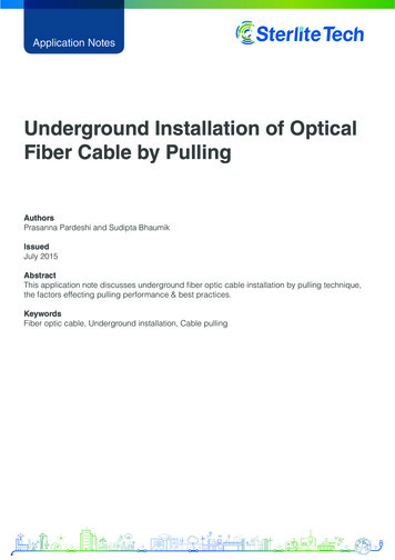
National Grid / Supplement to Specifications for Electrical Installations / ESB 759B July 20108.0 Transformer Clearance From a BuildingOil insulated equipment shall be located in compliance with the minimum clearances indicatedbelow. For existing buildings, the transformer shall not block access to existing building systems,such as wall mounted fire sprinkler systems. The building owner’s and/or tenants fire insurancecarrier or local inspection authority may restrict the proximity of the equipment to doors, windowsor combustible materials. It is the customer/developer’s responsibility to determine the acceptabilityof the proposed location of the orVentilating DuctNotes:1. Noncombustible material is defined as a material that will not ignite, burn, support combustionor release flammable vapors, when subjected to fire or heat, or as described by the latestedition of the NFPA-220.2. No portion of a building or building structure shall overhang any part of the pad-mountedequipment.3. In cases where required distances cannot be met, a noncombustible barrier, 6 foot minimumheight, shall be constructed. This barrier shall be designed to provide adequate fire protectionto the existing structure. A design for this structure shall be prepared and sealed by thecustomer’s Professional Engineer or Registered Architect and shall further be approved bythe local authority having jurisdiction of building code enforcement.4. For exits from a public assembly room, such as an auditorium, a 10 foot minimum clearanceshould be increased to 25 feet, unless there is a barrier.5. This requirement may vary between individual states. Refer to the building code regulationsfor the state involved.10 For the latest authorized version, please refer to the company’s website at ions.
National Grid / Supplement to Specifications for Electrical Installations / ESB 759B July 20109.0 Transformer Clearance From ObjectsClearances from objects:A. An area measuring 10 feet from any point of the transformer pad shall be kept free of all:buried water lines, storm drainage lines, gas lines, other electric lines;underground fuel storage tanks; andabove grade fire hydrants, cell towers, self contained diesel or diesel byproductfueled generators, and outdoor enclosed generators.Note: The 10 ft. clearance may be reduced with a noncombustible barrier (see Note 3) andshall not be less than five (5) feet from the edge of the transformer pad. The Customer or theirauthorized representative shall obtain this clearance reduction approval from the Company andthe local AHJ(Authority Having Jurisdiction), as necessary, prior to thenoncombustible barrier installation.B. An area measuring 25 feet from any point of the transformer pad shall be kept free of all:exposed water lines, gas piping, sewer lines;open conductor electric lines; andabove grade gas meters or regulator vents, fuel storage tanks or dispensing units,and non-enclosed gasoline/ propane / LP or LNG gas fueled generators.chemical storage silos / tanks.Note: The 25 ft. clearance may be reduced to 10 ft. with a noncombustible barrier(see Note 3) and shall not be less than five (5) feet from the edge of the transformer pad.The Customer or their authorized representative shall obtain this clearance reductionapproval from the Company and the local AHJ(Authority Having Jurisdiction), asnecessary, prior to the noncombustible barrier installation.10.0 Transformer AccessibilityEquipment shall be located within 10 feet of a way open to vehicular traffic and a minimum distancefrom any structure such as poles, fences, etc. as a means to permit accessibility for installation andmaintenance. A minimum of 10 feet of clear space shall be maintained in front of the equipmentdoors to permit installation and removal of separable connectors and fuses with shotgun stick.For the latest authorized version, please refer to the company’s website at ions. 11
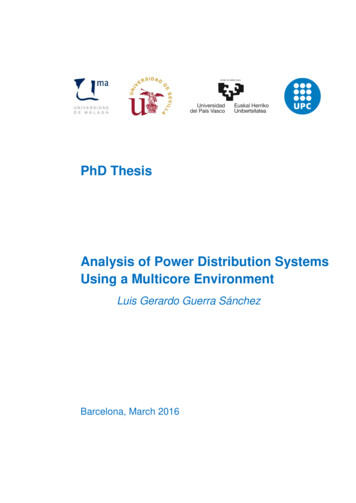
National Grid / Supplement to Specifications for Electrical Installations / ESB 759B July 201011.0 Transformer Mechanical Protection/BollardsWhenever possible, equipment should be located so it is not subject to vehicular damage. Ifthis is not feasible, adequate guards such as concrete filled pipes (Bollards) shall be placed toprotect the equipment.Bollards shall consist of 6 inch minimum diameter hot dip galvanized or painted steel pipes filledwith concrete. When Bollards can not be painted at the time of installation, painted covers shallbe installed. Page 56 shows manufacturer. Bollards are to be 5 feet above the ground and aminimum of 4 feet below the ground. Bollards to be set in a concrete footing as shown in detailbelow. Concrete is to be crowned on top of all bollards. Bollards shall be installed with due careto avoid interfering with ground grid and conduits. Refer to Pages 37 thru 40 for TransformerPad dimensions. For switchgear locations, see pages 34 and 35.The number, type (galvanized or steel) and locations of bollards shall be determined by DistributionDesign/Planning, taking into account proximity to traffic and to buildings as well as other barriersto traffic. Other factors such as salt spray and fertilizers may impact type of bollard required.Suggested bollard locations and dimensions are shown below. The location of bollards shallnot impede a door opening of 100 degrees.Blow up drawing detailing this is located on page 44Bollards RequiredBollards Not RequiredxNotes:1. Six foot minimum clearance from front of pad.2. Distribution Design/Planning shall designate thenumber and location of Bollards by marking theBollards of this drawing as follows:3. Bollards shall be supported with a 12” minimumdiameter concrete footing 6” below grade to baseof the bollard.Picture of Bollard cover, use for whenBollards can not be painted.4. For installations around oil containment curbs,install bollards six feet minimum on all applicablesides.12 For the latest a
National Grid / Supplement to Specifications for Electrical Installations / ESB 759B July 2010 URD Specifications and Installation Guide Acknowledgement (Job Spec/Signoff Forms) The requirements and specifications outlined in this